8. Wearables
Wearables again!! YEAAAAAAAHHHHHHHH I love this subject
Inspiration and Research
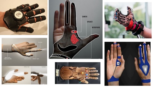
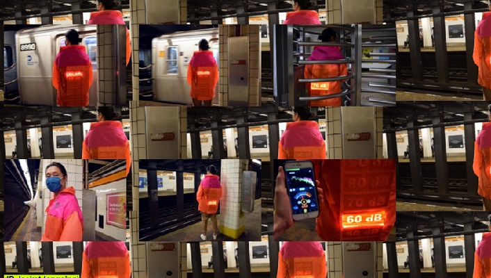
During this Week I understood deeper the extent of what it can be made with wearables. It is really inspiring to know that you can put living color, sound and movement to our clothes! In Lisa’s presentation, she mentioned the artist Kathleen McDermott who created a jacket that measures the decibels and display it a jacket.
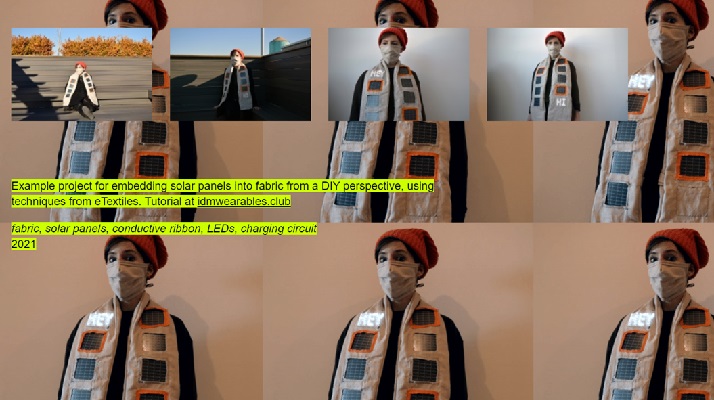
Then After further research, I found some other works she jas done and I found really inspiring this Scarf that has embedded solar panels and with that electricity she has two display screens.
Also, during the week, we played with different garments available in the lab. It was really interesting to see how the Termochromatic it works, and how it fades once it is in contact with a heated thread
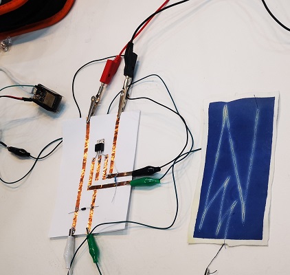
But personally, one of the best moments of the week was when we played a song of Bad bunny using an embroidered loudspeaker with a magnet.
How does speakers work?
Sound is vibration in the air. These vibrations can be generated with a temporary magnet (a coiled wire) connected to an audivisual signal attached to a membrane (fabric) and a static magnet. The temporary magnet will move based on the electronic signal causing the air to vibrate.
Circuit
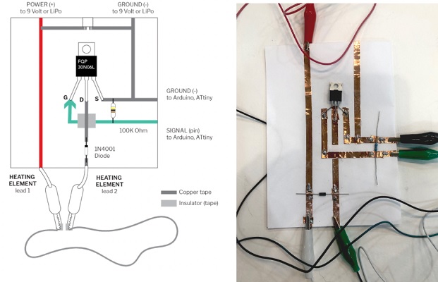
In switch mode, a transistor can be used to control the flow of electrical current. When used as a switch, the transistor operates in one of two modes: cutoff or saturation.
To turn a transistor on, a small voltage is applied to the gate, which is connected to the base of the transistor. This voltage creates an electrical field that allows current to flow between the drain and the source of the transistor. Conversely, when the voltage at the gate is zero, the transistor is turned off and no current flows through the circuit.
Using an Arduino, a microcontroller board, it is possible to control the voltage at the gate of the transistor, thus controlling the flow of current through the circuit. This can be used in various applications, such as in motor control or in the regulation of voltage or current.
Overall, the transistor's ability to act as an electrical switch is essential in many electronic devices, and controlling it through a microcontroller board like the Arduino provides a means of easily and precisely regulating electrical current flow.
Further details and alternative explanations, you can check in the webpages of my friends Alve and Dinesh :)
Materials and Process
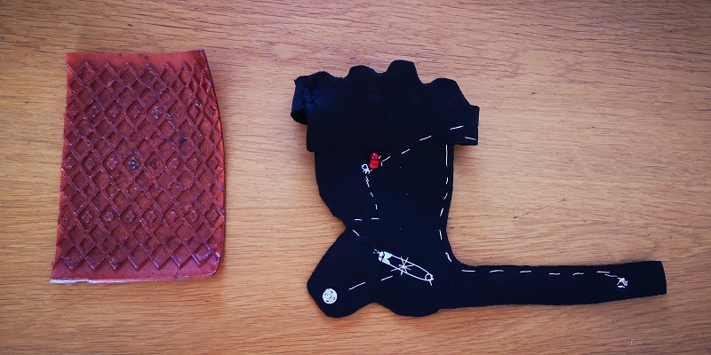
Following this weeks’ assignment, I was thinking about making a funny ugly Christmas jumper with lights and sounds, similar to those I have seen in the stores. However, after discussing the subject with my classmates and mentors, I decided that I will make an upgrade in my previous assignment I have done for Week 5. But this time, I will have control of more LEDs and I will have vibrating interaction when closing the Glove
Materials
- Wearable Glove – Created in assignment 5
- Gelatin BioPLastic – Created in Week 6
- NeoPixels RGB LED Weatherproof Strip 60 LED -1m
- Vibrating Motor DC 1030
- Arduino Chip ESP32
- Conductive Tape
- Conductive Thread
- Silicon
- Breadboard
I replaced the LED for neopixels, I added a vibrating motor that moves every time that the velostat is modified, and the Velostat will be the input sensor of my circuit. So every time that I press the sensor, a sequence of LED’s is changed and every change y followed by a vibration. Moreover I used one of the gelation bioplastic I created in Week 6 :D
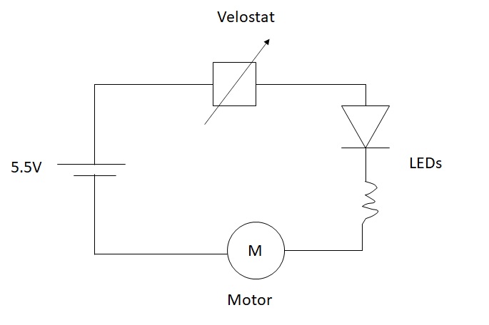
Considering the above, the first step was to test the circuits in the breadboard to be sure that it works without any problem. In this case I have 3 circuits: Neopixels, Vibrating Motor and Sensor. To control the Circuits I will use the Chip ESP32.
NeoPixel
My idea was to fix each LED to an unique color every time that you pushed the button. Everytime that the button was pushed, a new LED changed from White color to a specific Color. This was be done by setting a voltage to a specific position and in Arduino, you need to download the NEOPIXEL Library.
- pixels.setPixelColor(0, 255, 0, 0); // red
- pixels.setPixelColor(1, 0, 255, 0); //green
- pixels.setPixelColor(2, 0, 0, 255); //blue
- pixels.setPixelColor(3, 255, 255, 0); //Yellow
- pixels.setPixelColor(4, 255, 0, 255); //magenta
- pixels.setPixelColor(5, 255, 128, 0); //orange
- pixels.setPixelColor(6, 255, 255, 255); //white
Before I started the actual programing, Ithought about the actual sequence that the circuit shall follow:
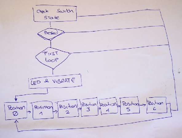
Once This was defined and configured (after several hours....), I determined that for each position, a number of LEDs shall be turned On and OFF, and then, once the programming was working, meaning this that the LED’s changed as I pushed the button, I proceeded to include the vibration.
Finally, once the motor vibrated after the button was pressed, I proceeded to replace the button with a conductive tape , and then I linked this conductive tape with the TochRead of the Chip esp32.
For ease of reference, this is the code I used to program my circuit (You need to import Adafruit_NeoPixel.h library
#include <Adafruit_NeoPixel.h>
#define PIN            12
#define NUMPIXELS      6

int But = 27;
int counter = 0;
int buttonState = 0;
int prestate = 0;

bool pressed = false;
int treshold = 30;

Adafruit_NeoPixel pixels = Adafruit_NeoPixel(NUMPIXELS, PIN, NEO_GRB + NEO_KHZ800);


void setup() {
  // put your setup code here, to run once:
  pinMode(But, INPUT);
  pinMode(13, OUTPUT);

  pixels.begin(); // This initializes the NeoPixel library.
  pixels.show();            // Turn OFF all pixels ASAP
  pixels.setBrightness(64); //from 0 to 255, use it only in setup

  Serial.begin(9600);

}

void loop() {
  Serial.println(touchRead(T0));
  buttonState = digitalRead(But);

  if (touchRead(T0) < treshold && pressed == false) {
    counter++;
    if (counter > 6) {
      counter = 0;
    }
    pressed = true;
    digitalWrite(13, HIGH);
  }
  else if (touchRead(T0) > treshold) {
    pressed = false;
    digitalWrite(13, LOW);
  }


  //Neopixels
  if (counter == 0) {
    pixels.setPixelColor(0, 255, 255, 255); // red
    pixels.setPixelColor(1, 255, 255, 255); //green
    pixels.setPixelColor(2, 255, 255, 255); //blue
    pixels.setPixelColor(3, 255, 255, 255); //Yellow
    pixels.setPixelColor(4, 255, 255, 255); //magenta
    pixels.setPixelColor(5, 255, 255, 255); //Orange
    pixels.show();  //display the color
  }


  //POS 1

  else if (counter == 1) {
    pixels.setPixelColor(0, 255, 0, 0); // red
    pixels.setPixelColor(1, 255, 255, 255); //green
    pixels.setPixelColor(2, 255, 255, 255); //blue
    pixels.setPixelColor(3, 255, 255, 255); //Yellow
    pixels.setPixelColor(4, 255, 255, 255); //magenta
    pixels.setPixelColor(5, 255, 255, 255); //Orange
    pixels.show();  //display the color
  }
  //POS 2
  else if (counter == 2) {
    pixels.setPixelColor(0, 255, 0, 0); // red
    pixels.setPixelColor(1, 0, 255, 0); //green
    pixels.setPixelColor(2, 255, 255, 255); //blue
    pixels.setPixelColor(3, 255, 255, 255); //Yellow
    pixels.setPixelColor(4, 255, 255, 255); //magenta
    pixels.setPixelColor(5, 255, 255, 255); //Orange
    pixels.show();  //display the color
  }
  //POS 3
  else if (counter == 3) {
    pixels.setPixelColor(0, 255, 0, 0); // red
    pixels.setPixelColor(1, 0, 255, 0); //green
    pixels.setPixelColor(2, 0, 0, 255); //blue
    pixels.setPixelColor(3, 255, 255, 255); //Yellow
    pixels.setPixelColor(4, 255, 255, 255); //magenta
    pixels.setPixelColor(5, 255, 255, 255); //Orange
    pixels.show();  //display the color
  }

  //POS 4

  else if (counter == 4) {
    pixels.setPixelColor(0, 255, 0, 0); // red
    pixels.setPixelColor(1, 0, 255, 0); //green
    pixels.setPixelColor(2, 0, 0, 255); //blue
    pixels.setPixelColor(3, 255, 255, 0); //Yellow
    pixels.setPixelColor(4, 255, 255, 255); //magenta
    pixels.setPixelColor(5, 255, 255, 255); //Orange
    pixels.show();  //display the color
  }
  //POS 5
  else if (counter == 5) {
    pixels.setPixelColor(0, 255, 0, 0); // red
    pixels.setPixelColor(1, 0, 255, 0); //green
    pixels.setPixelColor(2, 0, 0, 255); //blue
    pixels.setPixelColor(3, 255, 255, 0); //Yellow
    pixels.setPixelColor(4, 255, 0, 255); //magenta
    pixels.setPixelColor(5, 255, 255, 255); //Orange
    pixels.show();  //display the color
  }
  //POS 6
  else if (counter == 6) {
    pixels.setPixelColor(0, 255, 0, 0); // red
    pixels.setPixelColor(1, 0, 255, 0); //green
    pixels.setPixelColor(2, 0, 0, 255); //blue
    pixels.setPixelColor(3, 255, 255, 0); //Yellow
    pixels.setPixelColor(4, 255, 0, 255); //magenta
    pixels.setPixelColor(5, 255, 128, 0); //orange
    pixels.show();  //display the color
  }
  delay(100);
}
Embeding the circuit into the wearable
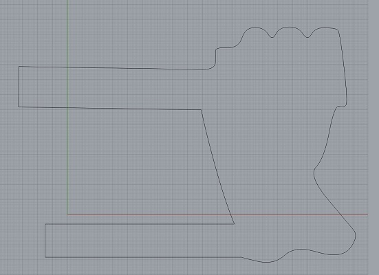
The first step was to cut the bioplastic with the shape of the glove.
Settings: The material I selected was 5mm thickness gelatin Bioplastic (refer to Week 6 for further details)
parameters for laser cut - 3mm Neoprene
Power: 20, Speed: 1 and PPI/Hz: 1000.
.
Recipe for Gelatin BioPLastic – Created in Week 6
Ingredients
-   240 ml of water avocado dye
-   48 gr of gelatin
-    30 glycerol
-   Pinch of Cinnamon
-   Pinch of Mica powder
parameters for laser cut - Gelatin Bioplastic
Power: 40, Speed: 1 and PPI/Hz: 1000.
Then I glued all the NEOPixels, motor and conexions into the Glove. I verified that all conections among the components worked, specially after the difficult process of welding.
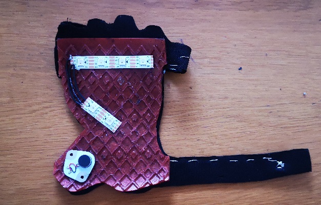
Finally, I added the Chip ESP32 to the circuit and my Wearable is ready to be used!!
Conclusions
Honestly, I really enjoyed this week and I learnt a lot of the possibilities that can be used in the fassion industry and wearables. In the lecture and tutorials , I understood more about circuits, alectronics and programming. But it was during the fabrication of my wearable, that basically you can build and program whatever you want. Music, lights and movement are available to be used when designing wearables !! :D
Thank you Petra, Ana and Josep 😊
References
Fabrication files
-
File: Sketch of the Glove ↩