7. COMPUTATIONAL COUTURE

INSPIRATION
Alumni's pages as an inspiration
FOOTWEAROLOGY VISIT
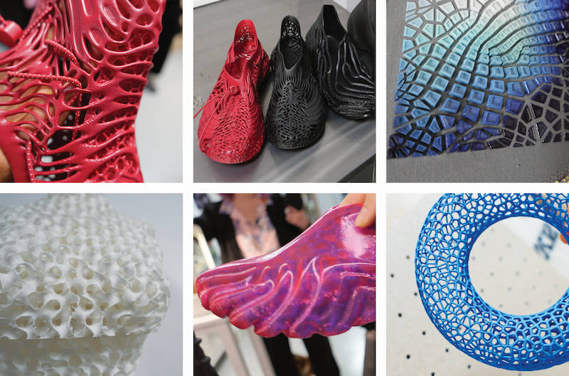
- In the lab they develop innovative projects focusing on 3D printing wearable shoes.
RESEARCH
COMPUTATIONAL DESIGN
Computational design is a collaborative and interdisciplinary approach that utilizes computer algorithms and digital tools to create, analyze, and optimize design solutions. The application of computational design can be found in different fields, such as architecture, engineering, industrial design, urban planning, and fashion. Using computers’ power, computational design can aid or automate parts of the design process, allowing designers to develop more intricate, efficient, and innovative solutions.
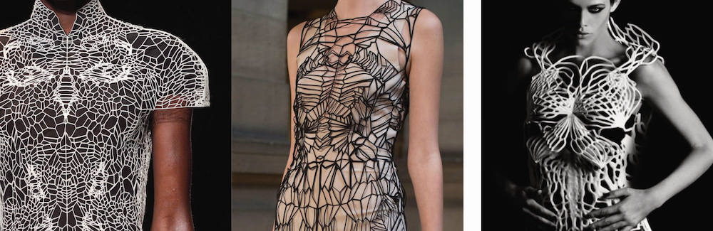
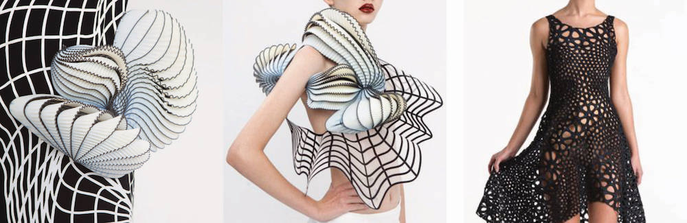
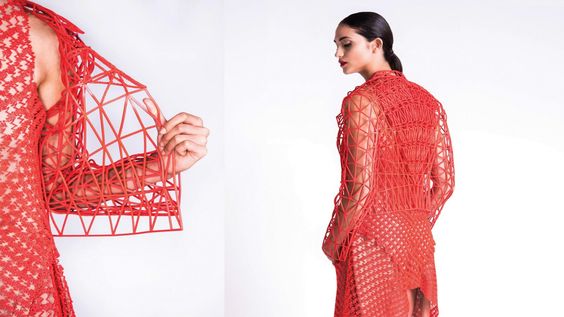
Fashion Design - Here are a few examples that caught my eye within this approach to design.
- Computational design tools (Grasshopper software) can generate intricate and unique patterns for fabrics. Designers can create complex, algorithmically generated patterns that would be difficult or impossible to achieve manually.
- Algorithms can generate patterns and designs tailored to an individual's body shape, resulting in a perfect fit.
- Algorithms can help design clothing patterns that minimize fabric scraps, contributing to sustainability in the fashion industry.
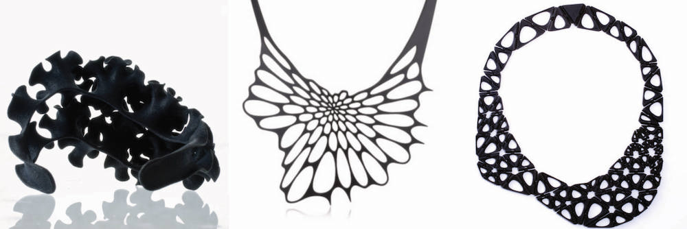
- Computational design tools can help prepare 3D models for printing and create detailed jewelry items that might be challenging to achieve through traditional manufacturing methods.
Computational design characteristics:
- Parametric Modeling
- Generative Design
- Simulation and Analysis
- Digital Fabrication
- Data-Driven Design
- Optimization
- Customization
- Human-Machine Collaboration
TOOLS
| SOFTWARE |
|---|
| - Rhino 7 & Grasshopper - Parametric Modeling |
| - UltiMaker Cura - free, easy-to-use 3D printing software. |
| - Anycubic Photon 3D Slicer Software - free 3D slicer software designed for resin 3D printing. |
| 3D PRINTERS |
|---|
| - Creality Ender-3 Pro - 3D printing filament types: PLA, PETG, ABS. |
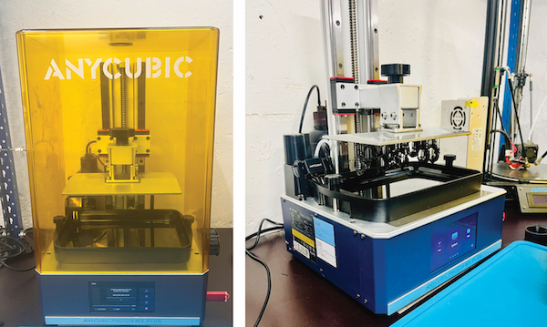
| - Anycubic Photon M3 Plus - resin 3D printing. |
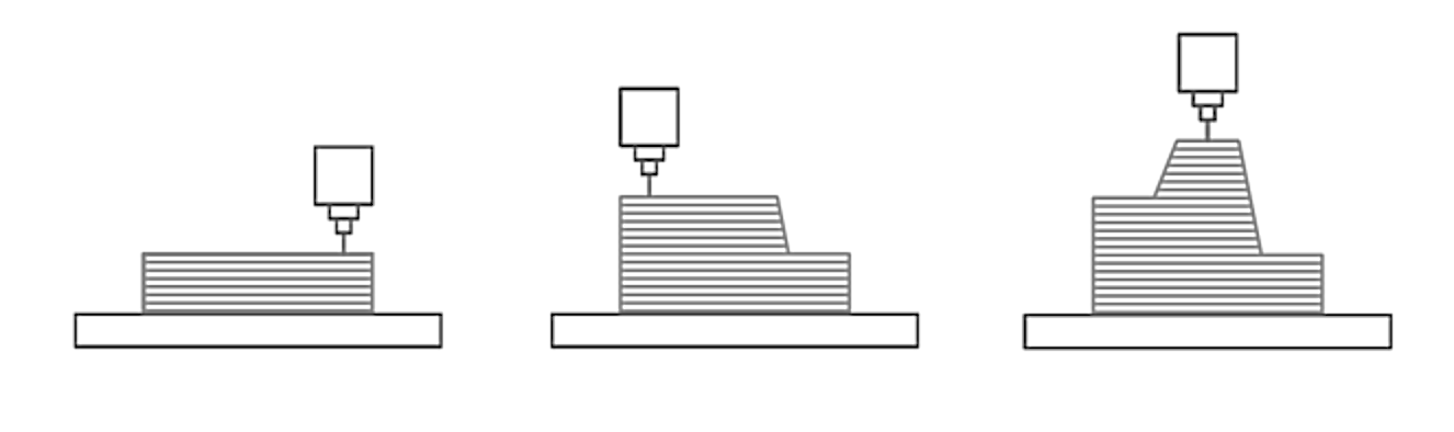
3D PRINTING
Additive manufacturing, commonly known as 3D printing, is a method of creating solid three-dimensional objects from a digital file. This process stands in contrast to subtractive manufacturing, which involves cutting out or hollowing out a piece of metal or plastic using a milling machine, for example. 3D printing allows for the production of intricate shapes using less material than traditional manufacturing techniques.
CHARACTERISTICS
- Rapid Prototyping: Quick and cost-effective production of prototypes.
- Reduced Material Waste: Traditional subtractive manufacturing processes often generate significant material waste.
- Complex Geometry: Creating parts with intricate internal structures.
- On-Demand Production
- Innovative Material Options: Constantly expanding the range of printable materials, including metals, ceramics, composites, and bioinks for tissue engineering.
- Weight Reduction: The ability to design and print lightweight structures can lead to weight reduction.
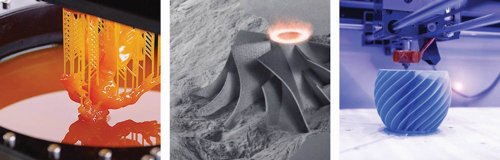
3D PRINTING TECHNOLOGY
| 3D PRINTING TECHNOLOGY | TYPE |
|---|---|
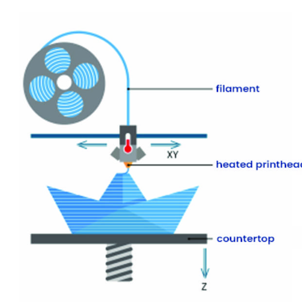 |
FDM |
| Fused Deposition Modeling | |
| • Melts and extrudes thermoplastic filament | |
| • Lowest price of entry and materials | |
| • Lowest resolution and accuracy | |
| BEST FOR: Basic proof-of-concept models and simple prototyping | |
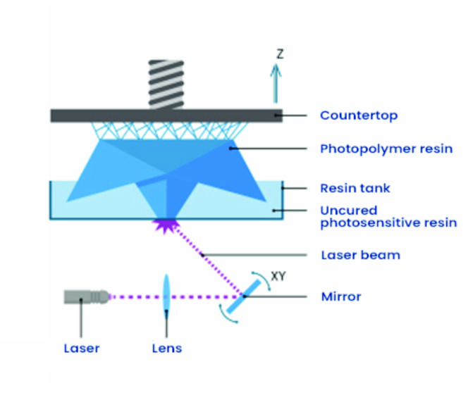 |
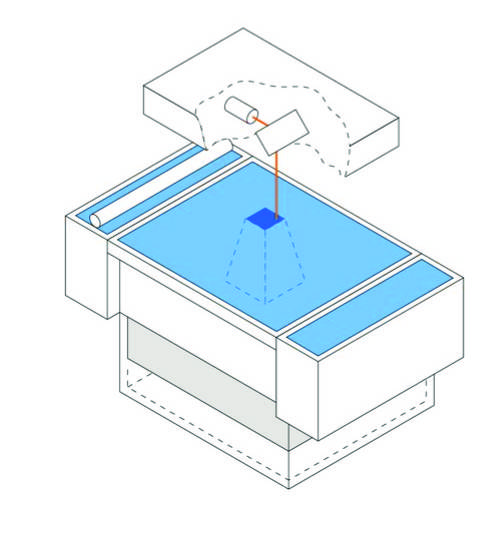
SLA |
| Stereolithography | |
| • Laser cures photopolymer resin | |
| • Highly versatile material selection | |
| • Highest resolution and accuracy, fine details | |
| BEST FOR: Functional prototyping, patterns, molds and tooling | |
 |
SLS |
| Selective Laser Sintering | |
| • Laser fuses polymer powder | |
| • Low cost per part, high productivity, and no support structures | |
| • Excellent mechanical properties resembling injection-molded parts | |
| BEST FOR: Functional prototyping and end-use production |
MY EXPERIENCES & IDEATION
I have limited experience with 3D printing and do not own a 3D printer myself. In the past, I have always worked with someone to complete 3D printing projects. Therefore, I was eagerly looking forward to attending a workshop that focused on how to work with a 3D printer. During the workshop, I gained a lot of new knowledge about how to prepare a model and how to work with the printer to meet the specific requirements of the chosen filament. Overall, the workshop was highly informative and engaging. Parametric modelling in Grasshopper is a hobby of mine that I'm enthusiastic about improving. I am grateful for all the workshops and advice I have received as I always gain new insights. The inspiring presentations of Julia Koerner and Brigitte's work have motivated me to explore new approaches with renewed vigor.
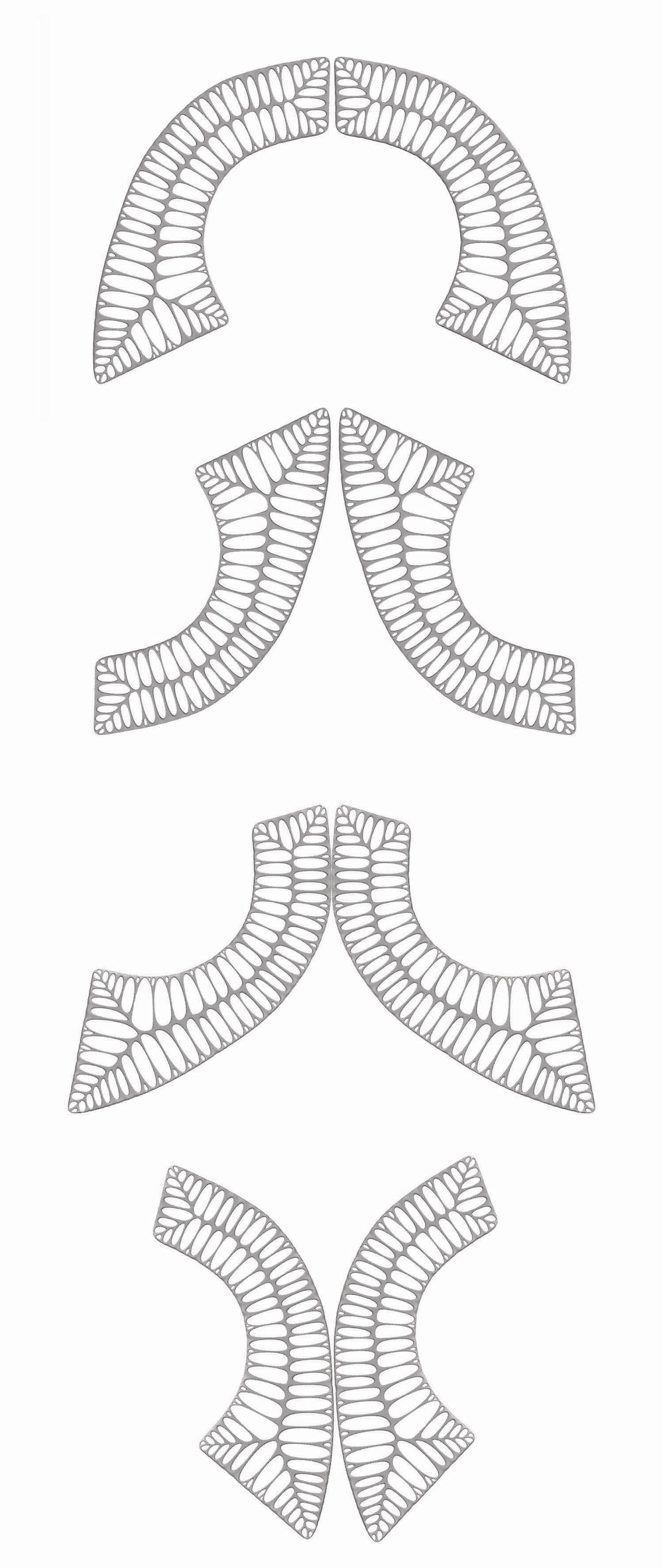
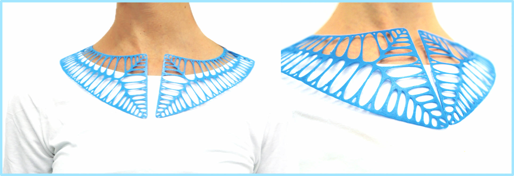
3D PRINTED COLLAR
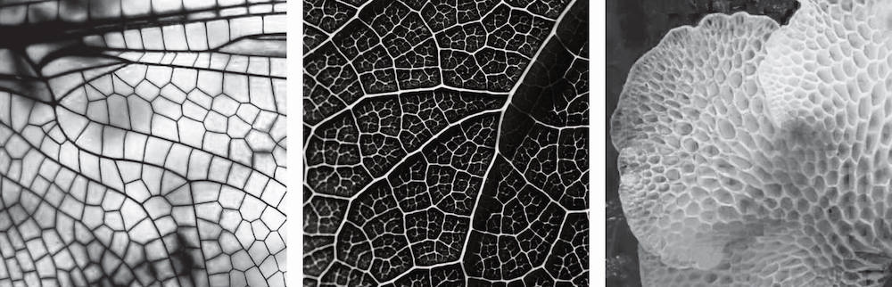
PATTERN IDEATION
1) Wings of a Green Darner Dragonfly, 2) Leaf pattern, 3) Favolaschia pustulosa
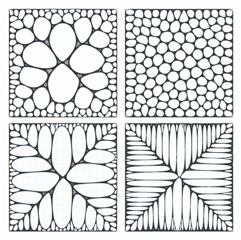
GEOMETRY IN NATURE - VORONOI DIAGRAM
Voronoi diagrams are a type of decomposition in mathematics that is determined by distances to a specific discrete set of objects in a metric space. This set of objects is usually a discrete set of points. The diagram is named after Georgy Voronoi, and is also known as a Voronoi tessellation, Voronoi decomposition, or Dirichlet tessellation (after Lejeune Dirichlet).
In the simplest case, we are given a set of points S in the plane, which are referred to as Voronoi sites. Each site (s) has its own Voronoi cell - also known as a Dirichlet cell - which consists of all points that are closer to (s) than to any other site. The segments of the Voronoi diagram are all the points in the plane that are equidistant to two sites. The Voronoi nodes are the points that are equidistant to three or more sites.

Coloured Voronoi 3D slice, Link
LLOYD'S ALGORITHM
The Voronoi diagram is still fascinating. I wondered if it could be symmetrical and spread evenly over a surface. After some research, I discovered Lloyd's algorithm. Using Lloyd's algorithm in Grasshopper to optimize a Voronoi surface involves iteratively adjusting the positions of the seed points (generators) of the Voronoi diagram to create a more even distribution of cells.
REFERENCES
PROCESS AND WORKFLOW
Initially, I created a flat Voronoi model and was curious about applying Lloyd's algorithm. What helped me the most was the discussion.
MY FIRST SKETCH OF THE PROCESS
Voronoi Diagram Setup: Start by creating a Voronoi diagram in Grasshopper. You can do this using the "Voronoi 2D" component found in the "Maths > Vector" tab.
Initial Seed Points: You need to define initial seed points (generators) for the Voronoi cells. You can do this by creating a set of points or using a grid of points.
Lloyd's Algorithm Implementation: Implementing Lloyd's algorithm for optimizing the Voronoi diagram:
a. Set up a loop to perform the following steps multiple times (iterations): Use the "Polygon Centroids" component to calculate the current centroids of the Voronoi cells. Calculate the average position of the vertices of each cell to determine the new positions for the seed points.
b. Adjust the positions of the seed points based on the calculated centroids. You can do this using components like "Move," "Vector Average," or "Average."
c. Re-run the Voronoi diagram with the updated seed points.
d. Continue iterating the process for a set number of iterations or until convergence (when the changes become negligible).
Visualization: Using components "Voronoi 2D" for the new seed points and Voronoi cells.
Parameters and Control: Control parameters for the number of iterations and convergence criteria to manage how many times Lloyd's algorithm runs and when to stop.
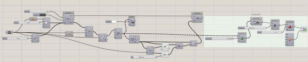
MODELING IN GRASSHOPPER
PLUGINS
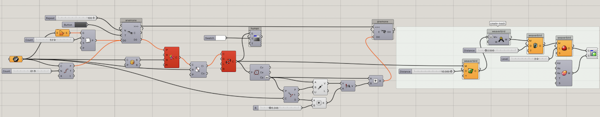
MODELLING PROCESS IN GRASSHOPPER
```

1)  Using Rhino, draw a boundary curve and create a surface with fewer points inside.

2)  Create a dense Voronoi structure by adding more points along the curve edge.

3)  Before starting the Anemone loop, it is important to create a bounding box around the curve.

4)  Trim curves outside the original using Voronoi and region.

5)  Use CONNECT CURVES to close perimeter cell boundaries.

6)  Lloyd's Algorithm recalculates the Voronoi cell centroid, resulting in a more evenly distributed configuration.

7)  Revise the text to obtain the point on the boundary curve closest to each cell's center point.

8)  Create a vector from the closest points to the original center points with an amplitude as a factor of their distance from the boundary curve.

9)  This results in a more pronounced distribution of points near the boundary curve due to the farthest translations of the points farthest away from the curve.

10) Add the original center points and translated center points together to recalculate the Voronoi.

11) To create a mesh around the cells, use a PICTURE FRAME.

12) At last, join, thicken, and smooth the surface.

```
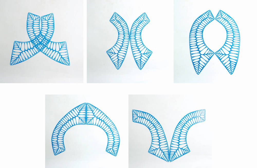
- The script is a powerful tool that allows you to manipulate and combine multiple parameters with ease. My intention was to create a script that could be used for different shapes and modified using parameters to change its visual character. Below, I am testing out irregular curve shapes.
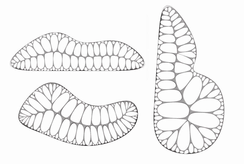
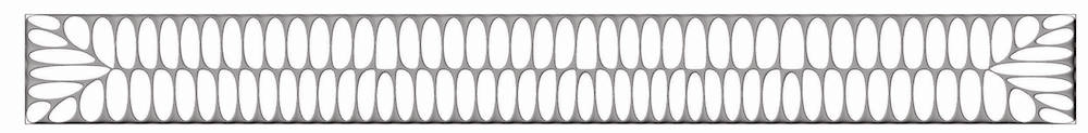
PATTERN SELECTION
- When I multiply the second item, the pattern I prefer emerges. The points furthest from the curve are translated the most, resulting in a more pronounced distribution of points near the boundary curve.
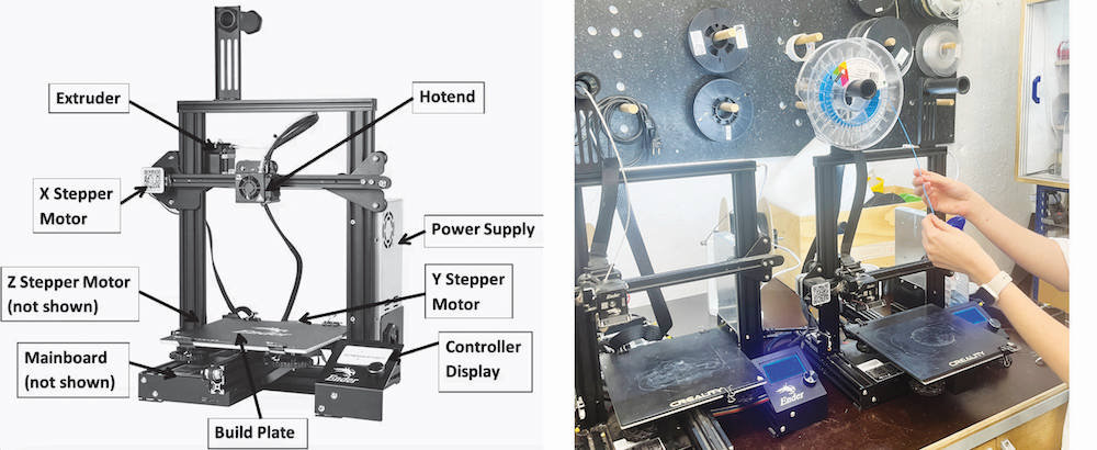
FABRICATION
In Fablab BCN we have Creality CR 1055 and Ender-3 Pro. For the fabrication I used Ender-3 Pro.
MATERIAL - FILAMENT
| Smartfil Flex: flexible filament TPU | COLOR | flexibility | DIAMETERS | Head temperature | Temperature table |
|---|---|---|---|---|---|
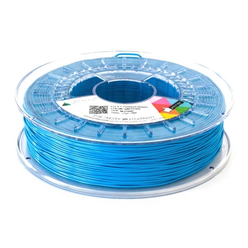 |
sapphire | 93A | 1.75 mm/2.85 mm | 210-230 degrees | 0-60 degrees |
SLICER - UltiMaker Cura
Once the design was finished in Rhino (it is better to export mesh!!), I exported it as an STL file. For information on print settings and the UltiMaker Cura software interface, refer to the documentation.
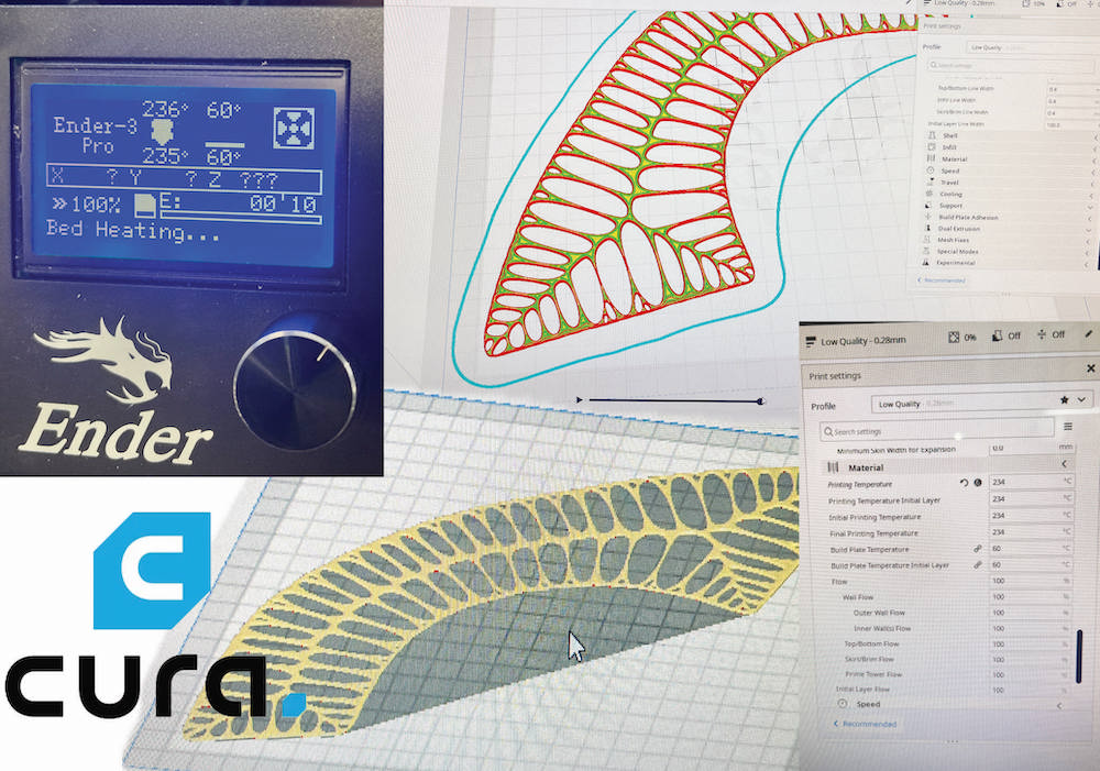
Configuring Ultimaker Cura settings for 3D printing involves adjusting various parameters to achieve the desired print quality. The specific settings you choose can depend on factors such as the type of 3D printer, the material you're printing with, and the characteristics of the object you're printing.
Ultimaker Cura settings - BASICS
-
Printer Settings: Select your 3D printer model from the list of available printers. Configure print bed dimensions and print volume. Set the nozzle size and initial layer height.
-
Material Settings: Choose the type of filament you're using (PLA, ABS, etc.). Adjust print temperature based on the recommended temperature for your filament.
-
Set layer height: Lower layer height provides higher detail but may increase printing time. Adjust initial layer height and initial layer line width.
-
Infill Settings: Determine infill density: Higher density provides more internal support but may increase material usage and print time. - Choose an infill pattern (grid, lines, triangles, etc.).
-
Print Speed Settings: Adjust print speed: Higher speeds can reduce print time but may affect print quality. Set initial layer print speed and travel speed.
-
Support Settings: Enable or disable supports based on the geometry of your model. Adjust support overhang angle and support density.
-
Build Plate Adhesion: Choose a suitable adhesion type (skirt, brim, raft) to help with bed adhesion. Adjust adhesion settings, such as skirt distance and brim width.
-
Cooling Settings: Enable cooling to improve print quality. Adjust fan speed and minimum layer time.
3D Printer and filament settings
| Layer height | Line Width | Infill density | Printing temperature | Build plate temp. | Speed |
|---|---|---|---|---|---|
| Initial Layer - 0.28 mm | 0.4 mm | 0 | 234 °C | 60 °C | Print - 50 mm/s, Wall - 25 mm/s, travel 150 mm/s |
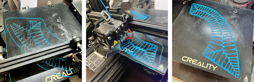
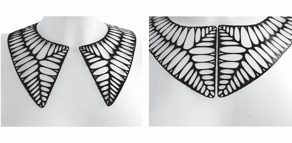
FINAL LOOK
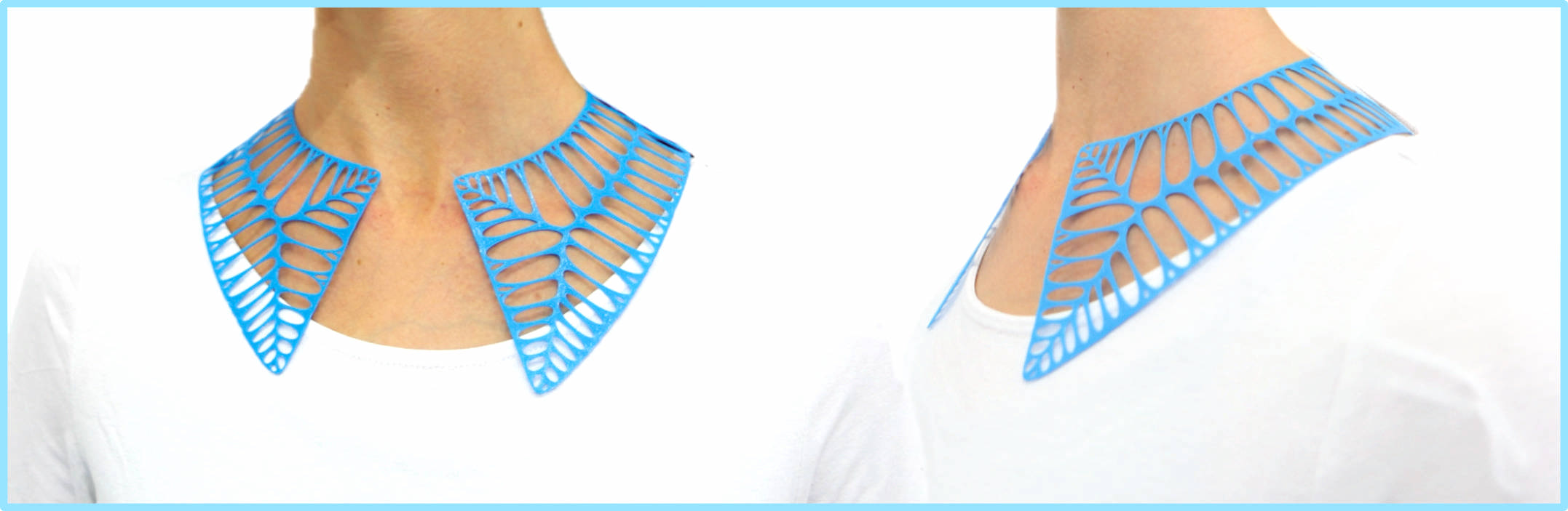
- I also like the more formal version of the collar in black.
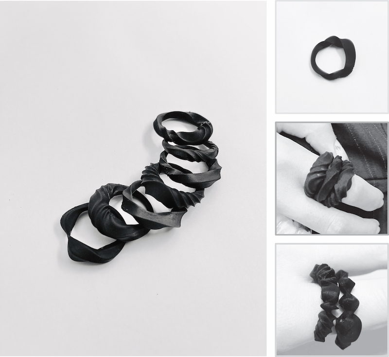
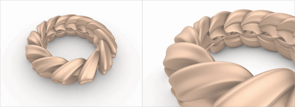
PARAMETRIC RING
- I really wanted to make a piece of jewelry that would be wearable right after printing and try 3D printing from resin.
FIRST ATTEMPT AND IDEA
When considering how to create an interesting parametric ring, I decided to use various organic shapes and rotate them around a circle. I loved the way the shapes turned out, but I have run into a problem. They are very complex and preparing them for export and 3D printing would be quite challenging. In my opinion, one of the great advantages of Grasshopper is that we can create shapes that are ready for printing without much hassle.
MY FIRST SKETCH OF THE PROCESS
Curves around a circle
-
Create a Circle: Start by creating a circle as the base shape for your ring. You can use the "Circle" component in Grasshopper.
-
Create Profile Curves: Design the profile curves for your ring. These curves will define the cross-section of your ring. You can use various curve components like "Arc," "Interpolate," or "Control Points" to create the desired profiles.
-
Rotate Profile Curves: Use the "Rotate" component to distribute the profile curves around the circle. You can control the number of copies and their rotation angles to create the desired ring shape.
-
Intersect Profiles with Circle: Use the "Intersect" component to trim or split the profile curves based on the circle. This step ensures that the profiles follow the circular path.
-
Loft or Sweep: Connect the resulting profile curves to the "Loft" or "Sweep" component to create the surface of the ring. Make sure the order of curves is correct for the lofting or sweeping operation.
-
Adjust Parameters: To fine-tune the shape of your ring, you can adjust parameters like the circle radius, profile curves, and rotation angles.
-
Bake Geometry: Once you're satisfied with the design, use the "Bake" component to create the 3D ring geometry in Rhino.
REFERENCES
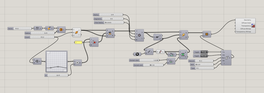
MODELLING PROCESS IN GRASSHOPPER
I have created a bracelet using grasshopper in the past. However, the surface of the bracelet turned out to be very uniform. While taking inspiration from the references mentioned above, I also wanted to implement my own design techniques.
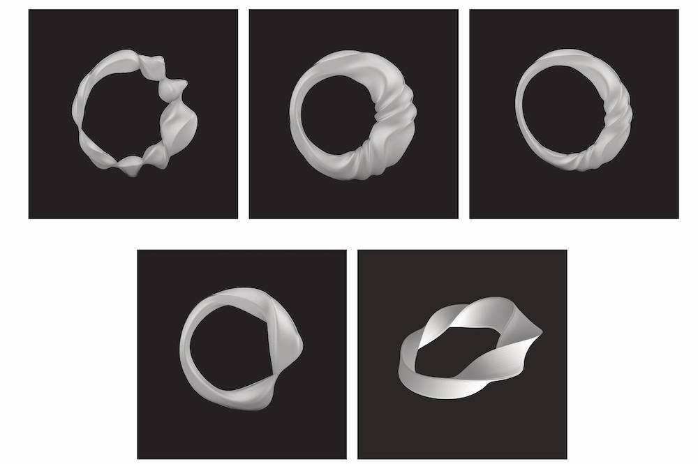
I had an idea to make a ring with an organic look, and I believed that curves would be the most natural choice. I began by drawing a circle as a base for the ring. Then, I added a certain number of planes on this circle and drew a polygon on each of them. I rotated these planes to create the twisted effect. To experiment with thickness, I created an attractor point. Due to this, the thickness of one side is varying.
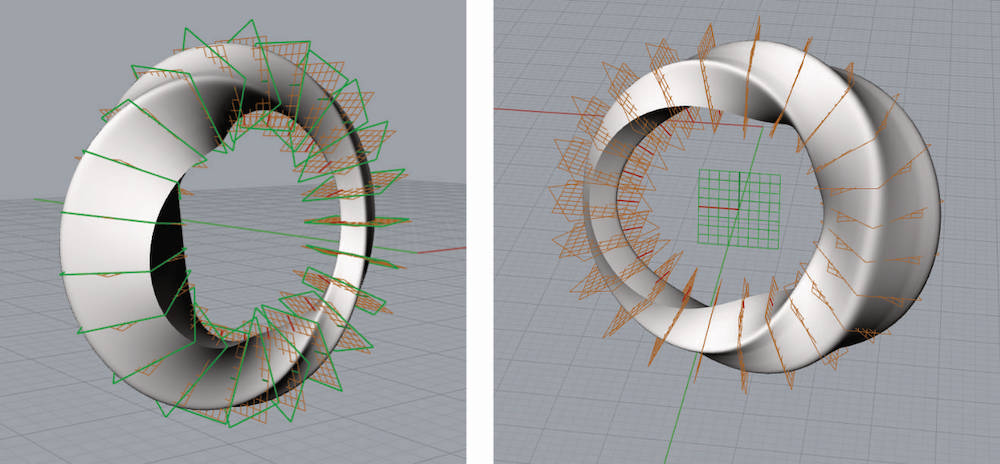
I used the graphmapper tool to give the ring a more natural and organic appearance. Using this tool, I was able to adjust the concentration of the turns and other aspects of the design. In this particular design, I created a section where there is no twist in the ring. When the rotation numbers are the same, there is no twisting. Additionally, the turns are more concentrated in some areas, which affects the overall twist of the ring. The flatter the line, the less the ring will twist.
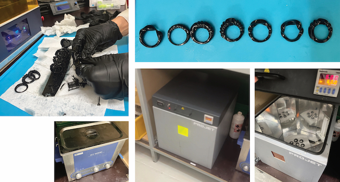
FABRICATION - 3D PRINTING WITH RESIN
- Stereolithography (SLA) process:
Resin Vat: The liquid resin is contained in a vat or tank. Layer by Layer Curing: A platform descends into the resin, and a UV laser or light source selectively cures the resin in a specific pattern, solidifying one layer of the object. Layer Increment: After a layer is cured, the build platform moves slightly upward, and the process repeats for the next layer. Build Progress: This layer-by-layer approach continues until the entire 3D object is created within the liquid resin.
TOOLS
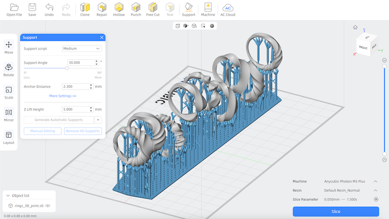
Anycubic Photon 3D Slicer Software
- Free 3D slicer software designed for resin 3D printing developed by Anycubic. It converts the stl/obj/xxx files into .pws or .photon files which can be read by Anycubic Photon printers.