5. E-TEXTILES

RESEARCH
I was eagerly anticipating this week because I believe the theme is essential for my future interactive design projects. I am particularly interested in the connection between textiles and electronics. Even though I've tried to work with Arduino in the past, I don't have much experience in this field. Many of the concepts I've learned are entirely new to me. So, I appreciate that we started by learning the basics of electrical circuits. We had amazing local and global workshops in BCN FabLab. This week we learned about voltage, resistance, current and circuitry, conductive materials, tools, hard/soft connections, soft sensors and programming basics using Seeed Studio XIAO ESP32C3 and Arduino IDE software.
We had amazing local workshops in our BCN Lab under the guidance of Gerard Montaño and Citlali Sánchez. With Citlali, we were focusing on working with the XIAO microcontroller.
This week I focused on discovery, taking small tests to explore my abilities with these tools.
INSPIRATION
1-2) Marija Dautartaite SENSATION MAP, 3) Liquid MIDI, 4) LIZA STARK Wearable Tech + Fashion Design Curriculum for Girls, 5) Marije Baalman Wezen – Chrysalis, 6) Maggie Orth
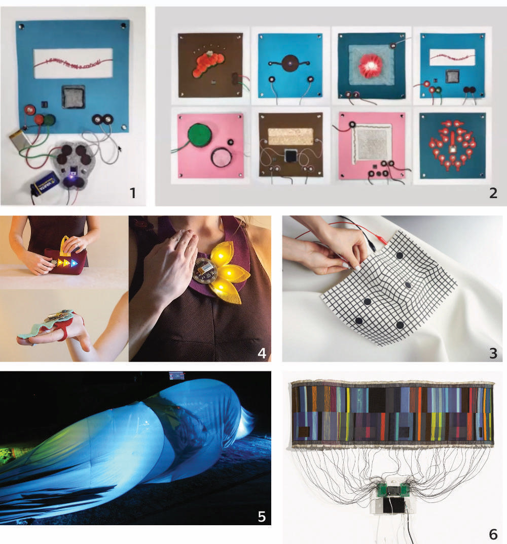
Alumni's pages as an inspiration
ELECTRICAL CIRCUIT BASICS
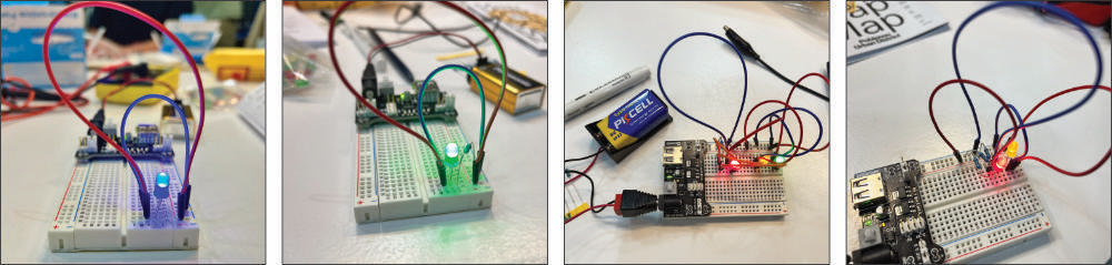
To understand electrical circuits, we wired LEDs for simple examples.
Ohm's law
Ohm's law states that the voltage across a conductor is directly proportional to the current flowing through it, provided all physical conditions and temperature, remain constant.
Ohm's law relates voltage (V), current (I), and resistance (R) in a circuit:
V = I * R
- Voltage (V) is the electrical potential difference that drives the current.
- Current (I) is the flow of electric charge, measured in amperes (A).
- Resistance (R) is a property of materials or components that opposes the flow of current, measured in ohms (Ω).
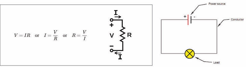
IMPORTANT TERMS AND CIRCUIT PRINCIPLE
The basic principle of an electrical circuit is the flow of electric current through a closed loop or pathway. An electrical circuit consists of several key components:
-
Voltage Source: This is the source of electrical potential energy that drives the flow of electric charge. Common examples include batteries and power supplies.
-
Conductors: These are materials (usually metals like copper or aluminum) that allow the flow of electric current. Wires or traces on a circuit board are examples of conductors.
-
Load: A load is a device or component in the circuit that uses electrical energy to perform a specific function. Examples include light bulbs, motors, resistors, and electronic components.
-
Switches: Switches are used to control the flow of current within a circuit. They can open (interrupt) or close (complete) the circuit, allowing you to turn devices on or off.
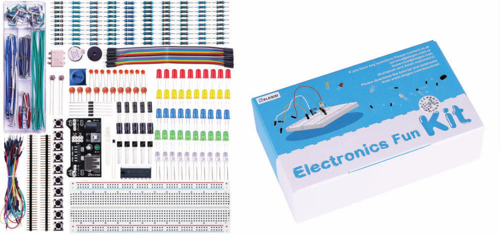
TOOLS
-
Software: Arduino IDE
-
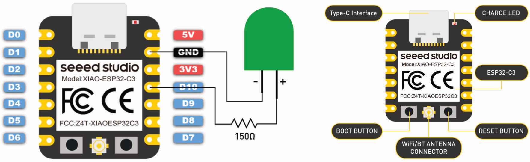
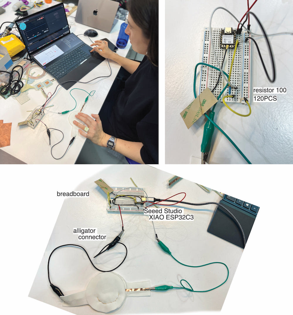
Hardware: Seeed Studio XIAO ESP32C3
THE SEEED STUDIO - XIAO
The Seeed Studio XIAO ESP32C3 is a development board or module that integrates the ESP32-C3 microcontroller. The board provides GPIO pins that can be used to connect sensors, displays, and other peripherals. It uses a USB interface for programming and power supply.
UNITS used to describe electrical circuits
- Volts (V) - A measure of electrical potential difference between two points in a circuit. In most modern passenger cars, light commercial vehicles and small craft this is 12V, however larger commercial vehicles, agricultural equipment and large boats may use 24V. Additionally some older cars and motorbikes may use 6V.
- Amperes (A) - A measure of the amount of electric current flowing past a point in a circuit in a given amount of time (commonly abbreviated to 'Amps')
- Ohms (R) - A measure of electrical resistance to the flow of current in a circuit.
- Watts (P) - Power, which is a measure of the rate at which an electrical circuit converts electrical energy into another form
DIGITAL X ANALOG CIRCUIT
Digital and analog electric circuits differ in how they represent and process electrical signals:
- Digital circuits use discrete, binary signals (0s and 1s) to represent information. These signals are often characterized by high or low voltage levels.
-
Analog circuits use continuous voltage or current signals to represent information. These signals can have any value within a certain range.
-
Digital circuits process data using logic gates and arithmetic operations on binary signals. They are inherently suited for discrete operations and digital data processing.
- Analog circuits use components like resistors, capacitors, and transistors to manipulate continuous signals. They are well-suited for tasks involving real-world, continuously varying data such as sound or temperature.
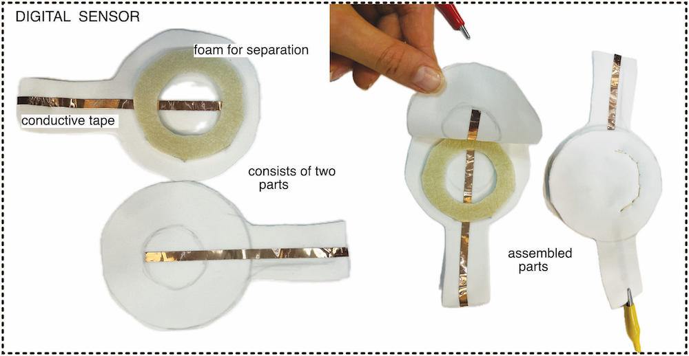
DIGITAL CIRCUIT
A digital circuit operates like an on/off switch.
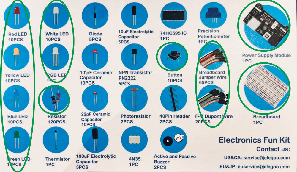
Materials
- Non Conductive Fabric
- Thin foam (separation)
- Seeed Studio XIAO ESP32C3
- Conductive copper Tape
- Conductive Thread
- 3V Coin Battery
- LED light
- Sewing Needle
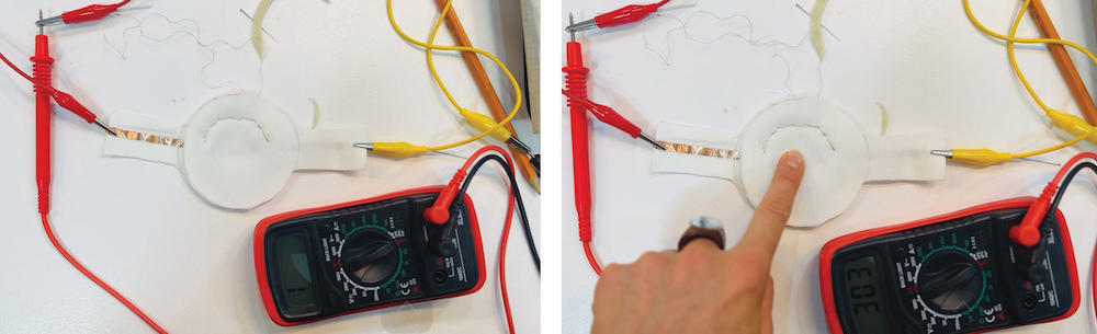
READ DIGITAL SENSOR
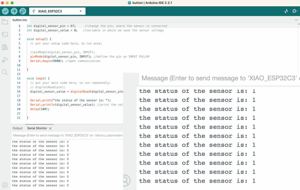
CODE
int digital_sensor_pin = D7;     //change the pin, where the sensor is connected
int digital_sensor_value = 0;   //variable in which we save the sensor voltage

void setup() {
  // put your setup code here, to run once:

  //pinMode(digital_sensor_pin, INPUT);
  pinMode(digital_sensor_pin, INPUT); //define the pin as INPUT PULLUP
  Serial.begin(9600); //open communication

}

void loop() {
  // put your main code here, to run repeatedly:
  // digitalRead(pin);
  digital_sensor_value = digitalRead(digital_sensor_pin); // read the sensor

  Serial.print("the status of the sensor is: ");
  Serial.println(digital_sensor_value); //print the value
  delay(100);

}
CODE EXPLANATION line by line
-
int digital_sensor_pin = D7;: This line declares an integer variable calleddigital_sensor_pinand assigns it the value D7. This is the pin number to which the digital sensor is connected. -
int digital_sensor_value = 0;: This line declares an integer variable calleddigital_sensor_valueand initializes it to 0. This variable will store the sensor's voltage or digital reading. -
void setup() {: This is the start of thesetupfunction, which runs once when the Arduino is powered up or reset. -
pinMode(digital_sensor_pin, INPUT);: This line configures thedigital_sensor_pinas an input pin. It sets up the pin to read data from the connected sensor. -
Serial.begin(9600);: This line initializes serial communication with a baud rate of 9600. This is necessary if you want to send data from the Arduino to a computer for monitoring or debugging. -
void loop() {: This is the start of theloopfunction, which runs repeatedly after thesetupfunction. -
digital_sensor_value = digitalRead(digital_sensor_pin);: This line reads the digital state (HIGH or LOW) from thedigital_sensor_pinand stores it in thedigital_sensor_valuevariable. -
Serial.print("the status of the sensor is: ");: This line sends a text message to the serial monitor, indicating that it's about to print the sensor's status. -
Serial.println(digital_sensor_value);: This line prints the value stored in thedigital_sensor_valuevariable to the serial monitor, followed by a newline character. This shows whether the sensor is reading HIGH or LOW. -
delay(100);: This line adds a 100-millisecond delay before the loop repeats. It slows down the loop, preventing the program from reading the sensor too rapidly.
ANALOG CIRCUIT
A circuit consists of a component that resists the flow of current.
Materials
- Non Conductive Fabric
- Thin foam (separation)
- Seeed Studio XIAO ESP32C3
- Conductive copper Tape
- Conductive Thread
- 3V Coin Battery
- LED light
- Sewing Needle
- Velostat
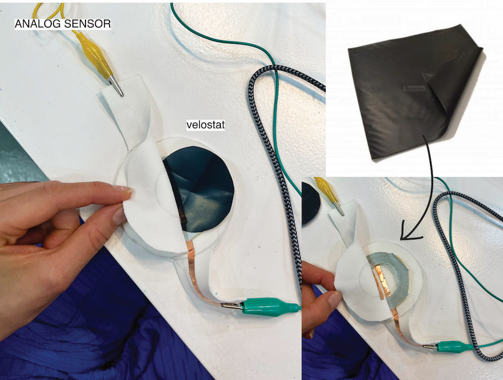
VELOSTAT
Velostat is electrically conductive, carbon-filled plastic sheet. It is used in applications related to electronics and sensor technology. Velostat can be used to make pressure-sensitive sensors or switches, and it's known for its ability to change electrical resistance when pressure is applied. It is useful in various projects, such as creating touch-sensitive interfaces or pressure-sensing devices.
READ ANALOG SENSOR
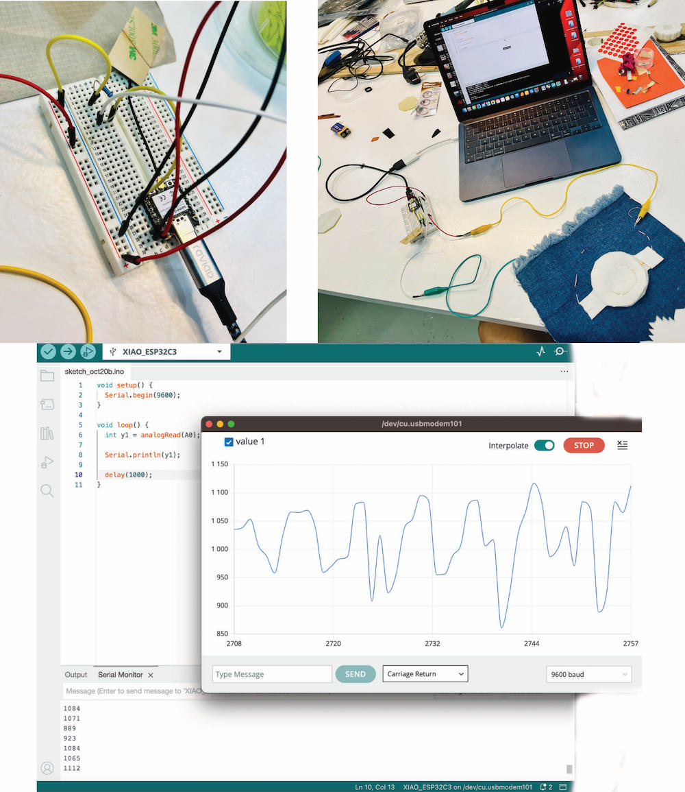
CODE
void setup() {
  Serial.begin(9600);
}

void loop() {
  int y1 = analogRead(A0);

  Serial.println(y1);

  delay(1000);
}
CODE EXPLANATION line by line
-
void setup() { This line indicates the beginning of the setup function, which is called once when the Arduino board is powered on or reset. In the setup function, you typically configure the initial settings for your program.
-
Serial.begin(9600); This line configures the serial communication with a baud rate of 9600 bits per second. It initializes the serial communication, which is often used for debugging and sending data to a connected computer.
-
} This curly brace marks the end of the setup function.
-
void loop() { This line indicates the beginning of the loop function. The loop function contains the main code that runs repeatedly in a continuous loop as long as the Arduino is powered on.
-
int y1 = analogRead(A0); This line declares an integer variable named y1 and assigns it the value obtained by reading the analog voltage from pin A0. The analogRead function is used to read the analog voltage on a specific pin, and the result is stored in the variable y1.
-
Serial.println(y1); This line prints the value of the y1 variable to the serial monitor. It is useful for monitoring and debugging, as it allows you to view the analog voltage reading on your computer when the Arduino is connected to it.
-
delay(1000); This line introduces a 1000 milliseconds (1 second) delay in the program. After printing the value to the serial monitor, the Arduino will pause for one second before looping and repeating the process.
-
} This curly brace marks the end of the loop function.
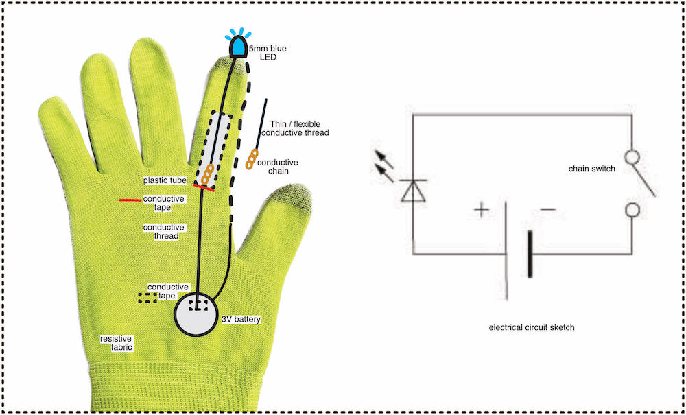
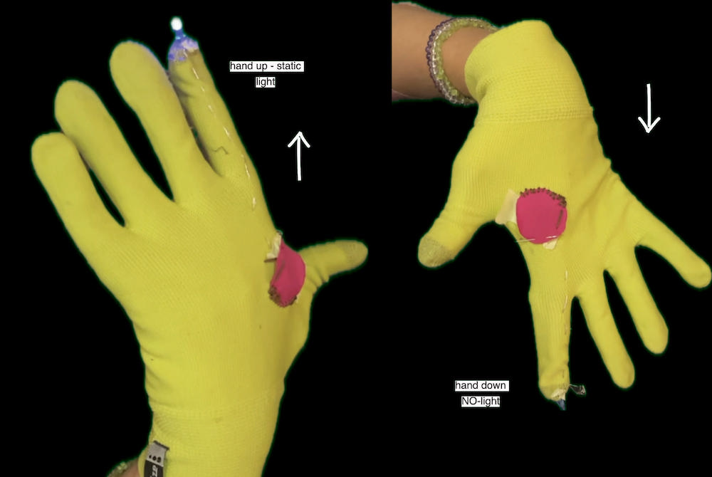
SHAKING SWITCH
RESEARCH & IDEATION
My intention was to create a sensor that would respond to motion and, at the same time, could be somehow linked to human body movement. I didn't want to create anything complicated and focused more on the mechanical aspect of the problem.
Inspiration -[Fabric tilt sensor] (https://www.kobakant.at/DIY/?p=6218)
Materials
- Non conductive fabric (or glove)
- Plastic / non conductive tubes
- Conductive chain / small beads
- Conductive tape
- Conductive thread
- 3V coin battery
- LED light (blue)
- Sewing needle
- Scissors
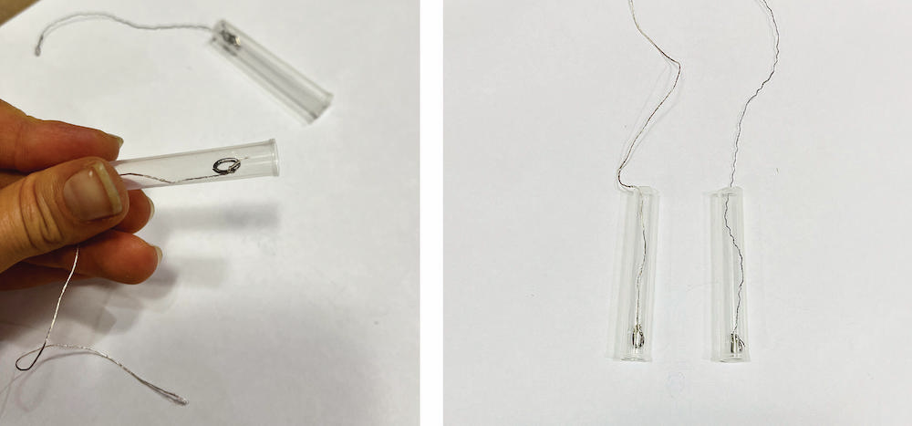
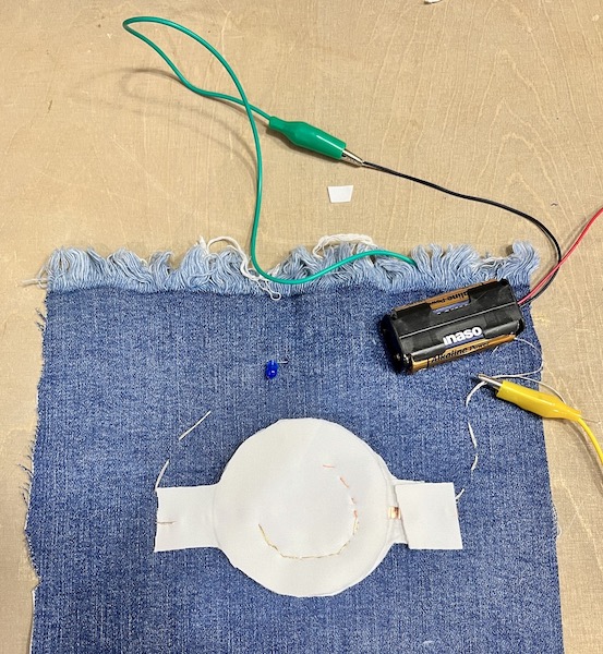
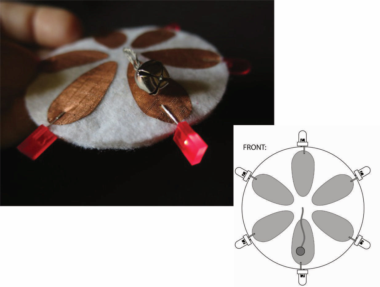
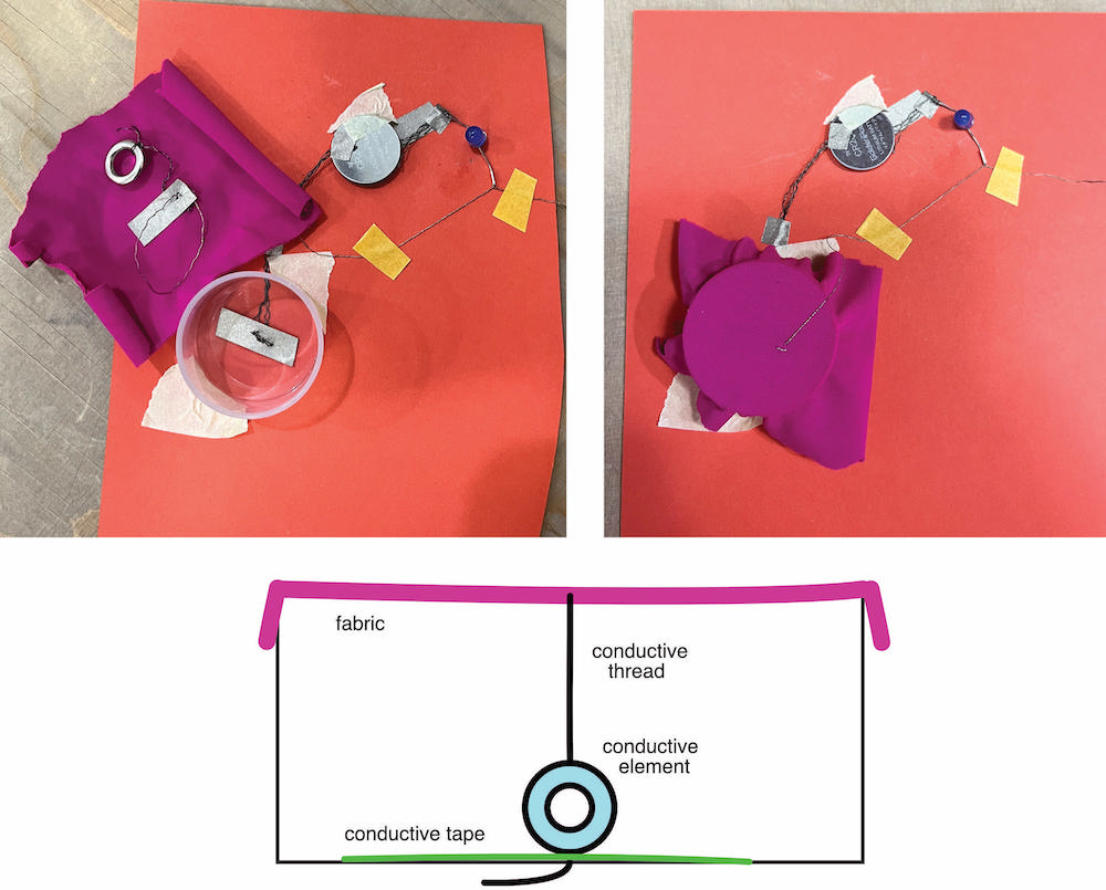
PROTOTYPING
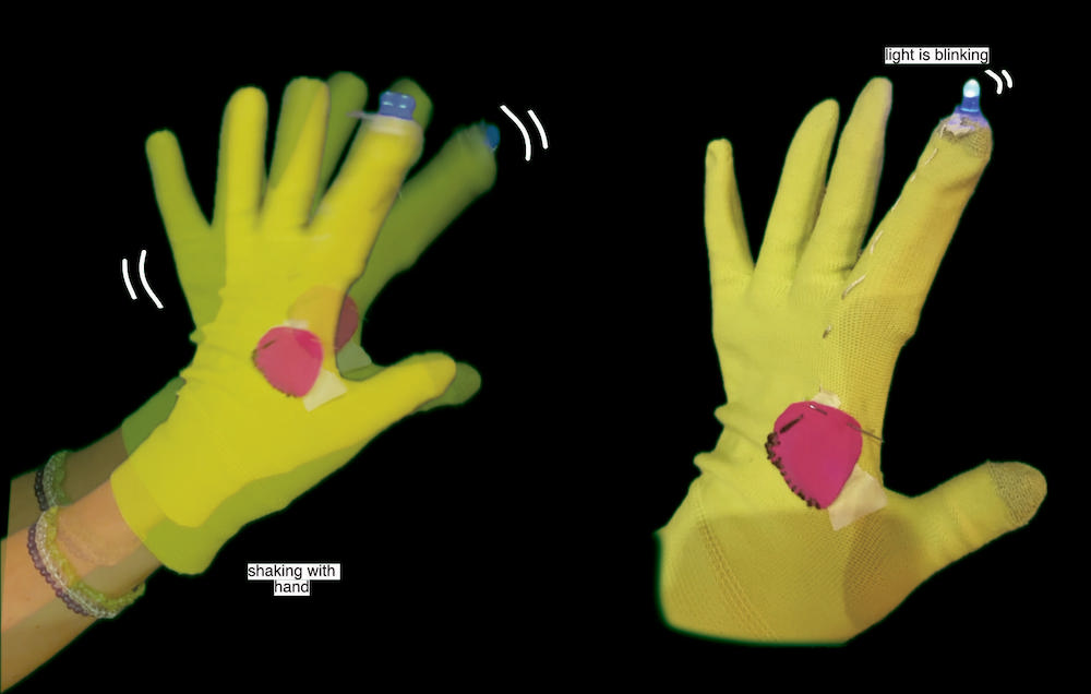
To begin with, I developed my idea using a paper prototype. Initially, I was unsure about how it would work exactly. I took a small plastic dish, covered it with fabric, and hung a conductive element from it. This system primarily worked when moving from right to left and vice versa. However, I was intrigued by the idea that the light would blink when I shook it. The LED light blinks when the conductive ring swings due to the inertial energy. Thus, I had two electrical circuit characteristics - motion and the inertial energy of swinging.
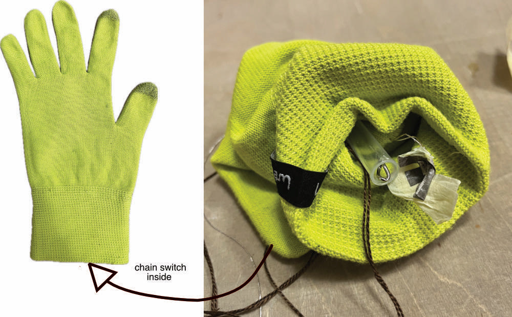
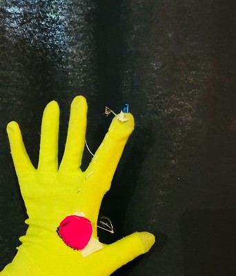
I then tried to apply the insights from testing to a sensor that would work in a different direction. The simplest application was in a glove.
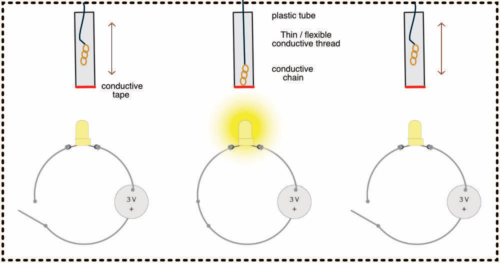
Testing was therefore necessary to determine the limits of using a stronger conductive thread. It was found that the thread was getting stuck in the tube, which could pose a risk to proper functionality. Additionally, it became evident that the thread was too strong, causing the chain not to move as it should. These findings are important for evaluating the possibilities of improvement and ensuring the proper movement of the chain in the tube. I have found that I will need to use a more flexible conductive thread that can move freely with the chain in the tube.