12. Skin Electronics
References
Bambi Medical
Bambi Medical is a medical device to monitor premature babies with less intrusive devices than usual. As any medical devices, it takes a long time before it becomes available to the market, so it is still not is use by now.

Jingwen Zhu
Designer/engineer Jingwen Zhu has been working on skin devices to have sensor which adapts to the body (articulation). She worked on sweat sensor which look like band aids and that can be used for healthcare monitoring.


Wendy Van Wynsberghe, capacitive sensor PCB
E-textile artist Wendy Van Wynsberghe has developed an open-source sewable PCB for a proximity sensor.


RFID: story of a failure…
Links
First, I tried to use a «RDM6300 RFID Reader - 125kHz» with a «S50 Mifare Tag Sticker». It didn’t work as S50 Mifare tags are newer tags with a high frequency (13.56 MHz). All the other tags I had in the lab were high frequencies.


So I ordered a new RFID/NFC reader: «RFID NFC Kit PN532»

I followed Electro Schematics tutorial to set it up. The first piece of code it gives (whose goal is to test the hardware) worked out fine, I could detect tags. But the second piece of code (to start experimenting) did not work. The Serial Monitor said that it could not find a PN53X board… Looking out for a solution, I found this post where it recommends to actually solder the pins above the antenna (white square) rather than below as the tutorial was saying. I could not manage to unsolder it for curious reason so I stopped this test here.


AtTiny, another failure…
I tried to follow Emma Pareschi’s ATtiny tutorial. There was an issue when installing the ATtinyCore boards because there was a certificate issue on the URL it tries to download the boards from.

Emma pointed out this forum question to solve the issue. Here is a summary.
Install ATtinyCore boards (for 64bits computers)"
- Add "http://drazzy.com/package_drazzy.com_index.json" in "File/Preferences/Additional Boards Manager URLs"
- on Linux
- Download this file: http://azduino.com/bin/micronucleus/micronucleus-cli-2.5-azd1-x86_64-linux-gnu.tar.bz2
- Place the file in this folder (Where
is your Linux username): /home/<username>/.arduino15/staging/packages/
- on Windows
- Download this file: http://azduino.com/bin/micronucleus/micronucleus-cli-2.5-azd1b-x86_64-mingw32.zip
- Place the file in this folder (Where
is your Windows username): C:\Users\<username>\AppData\Local\Arduino15\staging\packages\
- on MacOS
- Download this file: http://azduino.com/bin/micronucleus/micronucleus-cli-2.5-azd1-x86_64-apple-darwin.tar.bz2
- Place the file in this folder (Where
is your MacOS username): /Users/<username>/Library/Arduino15/staging/packages/
- In Tools/Boards Manager, search for "attiny", you should now be able to install "ATtinyCore 1.5.2". It might take a while but it ends up well.
I followed Emma’s tutorial steps:
- upload Arduino as ISP sketch on the Arduino board withouth anything connected.
- wire the ATtiny to the Arduino according to the schematics
- set the Arduino IDE settings according to my chip (here an ATtiny85)
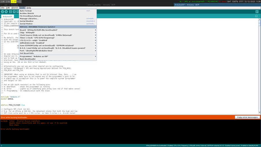
But I keep getting this error when trying the burn the bootloader:
avrdude: Device signature = 0x000000
avrdude: Yikes!  Invalid device signature.
         Double check connections and try again, or use -F to override
         this check.
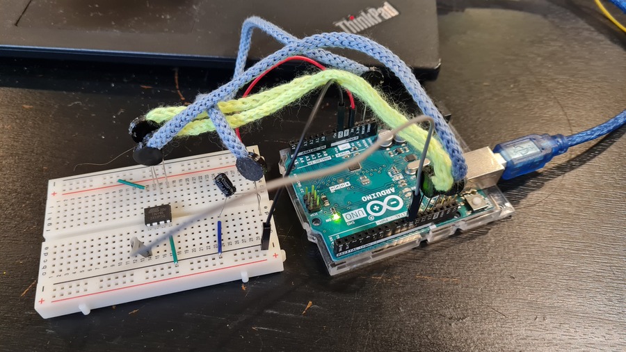
Capacitive sensor
This is a quite straightforward and fun experiment to do. I just lost 20 minutes of my time because I read one would need a resistor between 50 and 300 Ω, but it is actually a resistor between 50 and 300kΩ… If your resistor is not big enough, you get only 0 as output. Here I used a 100kΩ resistor and a sensor I used during week 5 on e-textile.
Capacitive sensor code
# include <CapacitiveSensor.h> // Install Capacitive Sensor library if you haven't already

CapacitiveSensor cs_4_2 = CapacitiveSensor(4,2); // 10 megohm resistor between pins 4 & 2, pin 2 is sensor pin, add wire, foil

void setup(){
    cs_4_2.set_CS_AutocaL_Millis(0xFFFFFFFF); // turn off autocalibrate on channel 1 - just as an example
    Serial.begin(9600);
}

void loop(){
    long total1 = cs_4_2.capacitiveSensor(30);
    Serial.println(total1); // print sensor output 1
    delay(100); // arbitrary delay to limit data to serial port
}
micro:bit
Inspired by the Bambi Medical project, I made a belt as temperature sensor for babies/toddlers or adults who lost communication means. I used a micro:bit microcontroller as it already has a temperature sensor in it. I had already coded a micro:bit in the past using their Blocks interface, but I wanted to try their Python interface for a change (and also because I love Python). The interface is also quite friendly as the reference is accessible on the left side of the screen. If you're looking for an element, you can search for it in the search bar and you would find it rather easily.

The sensor is located next to the chip which is always a bit warm. So one would have to adapt the temperature accordingly to obtain correct values. For example, in the video below, it starts at 22˚C as room temperature whereas it is actually 19˚C. The script changes a neopixel color according to the temperature of the body. It's blue when it's too cold, purple/pink when it's in a fine range, red when it's too warm.
Making it comfortable to wear
I braided the 3 wires of the neopixel so that it's not so cumbersome, and it's a bit long to pass it through a cardigan. The blue and black cords are from Green Fabric, the pink one I made using my three-latched tool for i-cord making that I made during week 10 Open Source Hardware. I used a transparent button to hide the neopixel board, a belt buckle and ribbon from Green Fabric second hand shop.
Future usage: it could be coupled with a heartbeat sensor and/or a breathing sensor to monitor those as well. The neopixel could blink according to the heartbeat, and another one could dim to show breathing.
PHOTOS BOUTON + BOUCLE


Code
from microbit import *
# Loads neopixel library
import neopixel
# Defines that the neopixel is connected to pin2 and that there's only 1 neopixel
np = neopixel.NeoPixel(pin2, 1)

while True:
    sleep(1000)

    # The function `temperature()` asks the thermometer for the temperature and outputs a number

    # If the temperature is below 23˚C
    # between 23˚C and 25˚C
    # above 25˚C
    # These values are for easy prototyping purpose, for a real usage you would change those values to normal body temperature values.
    # In parenthesis is the RGB color code. Each value is between 0 and 255: 0 being off, and 255 being full intense
    if temperature() <= 23:
        np[0] = (0, 0, 10) # blue
    elif temperature() > 23 and temperature() < 25:
        np[0] = (10, 0, 10) # purple
    else:
        np[0] = (10, 0, 0) # red

    # Lights the neopixel with its given value
    np.show()

    # Outputs the temperature on the micro:bit screen
    display.scroll(temperature())