6. Computational Couture
Research & Ideation
Computational Couture is an emerging design and fabrication technique that integrates additive manufacturing directly onto textile surfaces, creating hybrid materials that combine the flexibility of fabric with the structure and functionality of printed forms. Designers and researchers use this approach to build textures, reinforcement, functional elements, and interactive components that bond with woven, knitted, or nonwoven substrates. Depending on material choice and print parameters, 3D-printed elements can add stretch control, protection, ornamentation, or attachment points while maintaining fabric drape and wearability. This process expands the possibilities of textiles beyond flat surfaces, allowing fabrics to become active, customizable systems that support experimentation in fashion, performance wear, medical textiles, and wearable technology.
References & Inspiration
Anouk Wipprecht
Anouk Wipprecht is a Dutch fashion-tech designer known for pioneering interactive, robotic, and 3D-printed garments that respond to the body, environment, and human behavior. Her work sits at the intersection of fashion, engineering, neuroscience, and performance, treating clothing as an intelligent system rather than a static object. Wipprecht’s designs such as the iconic Spider Dress often incorporate sensors, motors, microcontrollers, and 3D-printed structures integrated with soft textiles. These garments can detect proximity, biometric signals, or emotional states and respond in real time, blurring the line between wearable technology and living architecture.
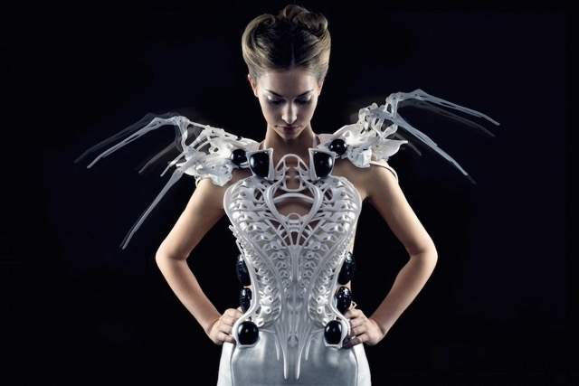
Photo from Make Magazine
Neri Oxman
Neri Oxman is an architect, designer, and researcher best known for pioneering the concept of Material Ecology, which integrates computation, biology, and digital fabrication to create materials and structures that behave more like living systems than static objects. Her work fundamentally reshapes how we think about design, moving beyond assembling parts to growing, programming, and fabricating materials with embedded function. As the founder and former director of the MIT Media Lab’s Mediated Matter Group, Oxman explored advanced fabrication techniques such as multi-material 3D printing, gradient structures, and printing onto flexible and textile like substrates. Her projects often blur boundaries between fashion, architecture, and science, producing wearable and body-related forms that respond to environmental forces such as light, heat, and stress.
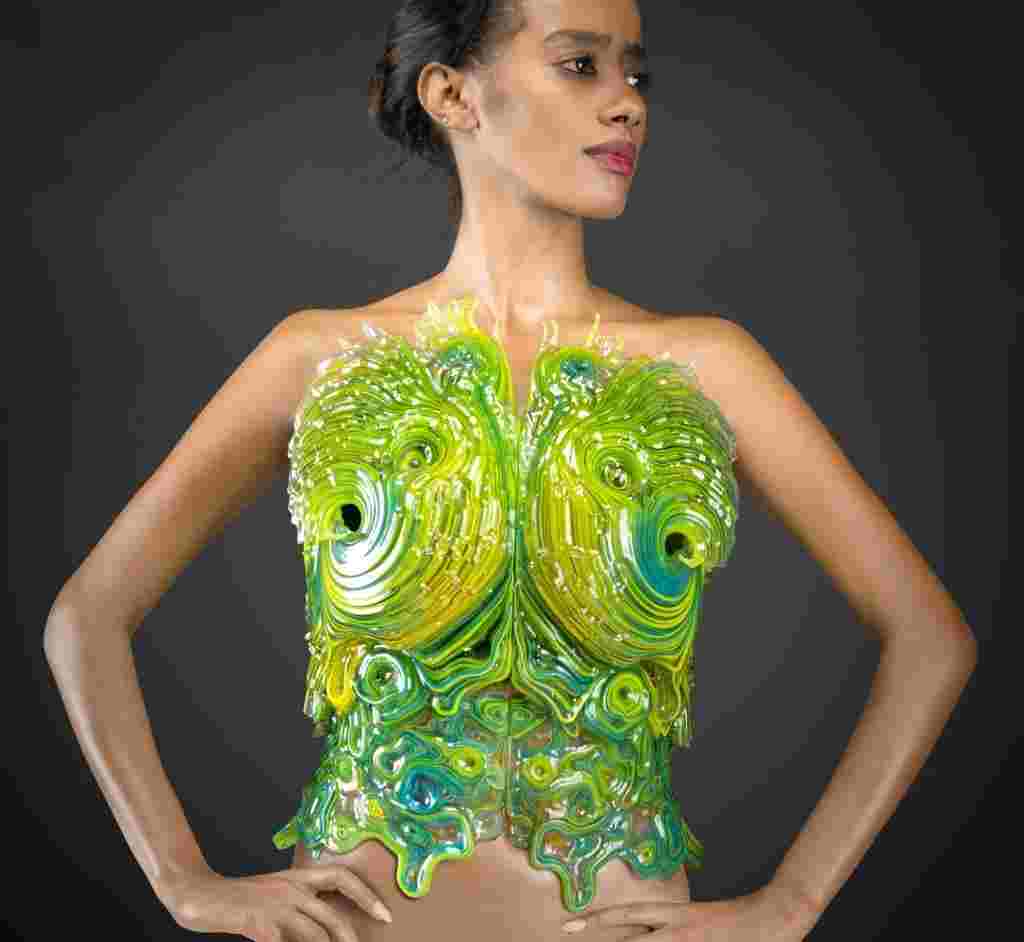
Photo from Yoram Reshef of Neri Oxman
Tools
Process and workflow
Rico Kanthatham’s Fabricademy tutorial introduces computational design through Blender Geometry Nodes as a way to think about textiles, surfaces, and structures as systems rather than static forms. His approach emphasizes process, parameters, and iteration, aligning closely with the philosophy of material experimentation and digital fabrication. Rather than modeling objects manually, Rico teaches students to build node-based workflows where geometry is generated through relationships—such as distribution, attraction/repulsion, noise, and instancing. These systems allow designers to control density, scale, orientation, and variation using sliders and values, making designs flexible and easily adaptable. Techniques such as noisy surfaces, attractor/repulsor fields, and instancing demonstrate how complex patterns can emerge from simple rules.
A key focus of the tutorial is non-destructive design. Geometry remains editable until the final stage, where instances are realized only when necessary for fabrication (e.g., exporting STL files). This mirrors textile logic—repetition, modularity, and responsiveness and supports applications such as 3D printing on fabric, hybrid materials, and computational couture. Overall, Rico’s tutorial reframes Blender as a material system design tool, helping students understand how computation can expand textiles beyond flat surfaces into programmable, customizable, and performative structures
Blender Geometry Nodes
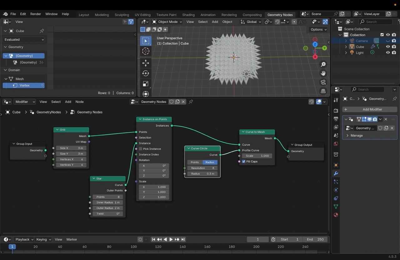
This Geometry Nodes system generates a procedural radial surface by instancing a star-shaped curve across a grid and converting it into a mesh. A Grid node establishes the base point distribution, functioning as a structured scaffold that controls where geometry will be placed. A Star curve is then instanced onto each grid point using Instance on Points, creating a repeating geometric pattern. To transform the curve instances into solid geometry, a Curve Circle is used as a profile and fed into a Curve to Mesh node. This extrudes the instanced star curves into volumetric forms, producing a dense, spiked radial structure. The final output is a parametric object whose complexity and density are controlled by grid resolution, star parameters, and curve profile size.
Step 1: 3D Printing
I orginally transferred the a hexagon star design from the Blender Geometry Nodes for 3D printing. The job was a 6 hour print and 55 layers; however, the filament keep pouring out sporatically. After a few attempts, I pivoted and found file from Thingyverse that created pentagons.
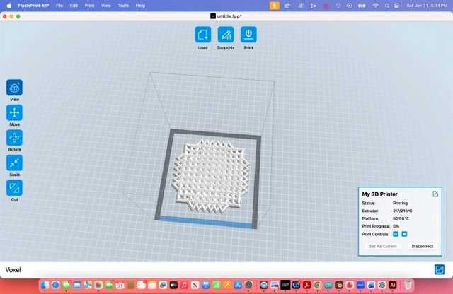
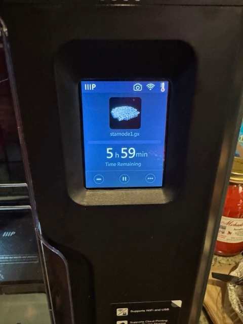
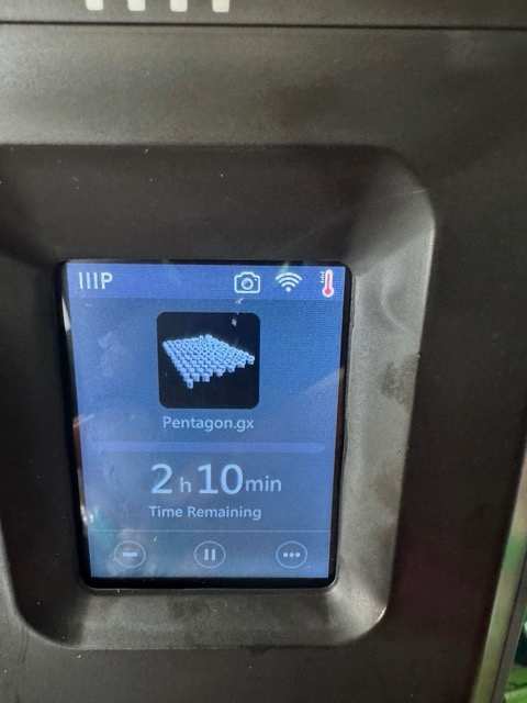
The Pentagon .gx file was printed from Thingyverse using the Monoprice Voxel 3D printer with FlashPrint (MP Slicer) as the transfer and verification tool. Because the file was sliced in .stl and had to transform it to a .gx format. I was able to create a star 3D print in geometry nodes in Blender but could not figure how to convert to be read for 3D slicing.
Step 2: Monoprice Voxel Printer
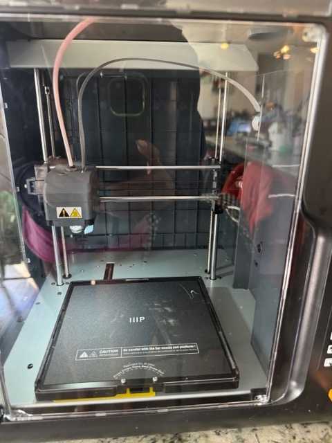
The Monoprice Voxel is a compact, user-friendly FDM 3D printer designed for reliable desktop fabrication. It supports PLA and uses the FlashPrint (MP Slicer) workflow, allowing files to be printed directly in the native .gx format. In this process, the printer was used to execute a pre-sliced file, emphasizing accuracy, material preparation, and first-layer adhesion rather than parameter tuning. Its enclosed build chamber, touchscreen interface, and straightforward file transfer (USB or Wi-Fi) made it well-suited for consistent prototyping and classroom or lab-based experimentation.
3D Printing on Tulle Fabric
For this experiment, I explored the integration of 3D printing and textiles by printing a 3D structure directly onto tulle fabric. The objective was to investigate how a rigid 3D-printed structure could be physically integrated with a lightweight, flexible textile.
Preparing the 3D Model for Printing
The 3D model was prepared for fabrication and opened in FlashPrint, the slicing software used with the FlashForge Voxel 3D printer. I positioned the model on the virtual print bed and prepared it for slicing.
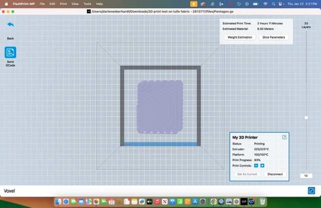
Before printing, I reviewed the slicing parameters and layer preview in FlashPrint. The model was sliced into a total of 33 layers. The estimated print time was 2 hours and 11 minutes, and the estimated material requirement was 6.00 meters of filament.
The sliced model was prepared as a .gx file, which contains the printer instructions used by the FlashForge Voxel.
Print Settings
The following slicing parameters were used to prepare the 3D model for printing:
| Print Parameter | Setting |
|---|---|
| 3D Printer | FlashForge Voxel |
| Slicing Software | FlashPrint |
| Sliced File Format | .gx |
| Layer Height | 0.18 mm |
| Perimeter Shells | 2 |
| Fill Density | 15% |
| Fill Pattern | Hexagon |
| Print Speed | 60 mm/s |
| Travel Speed | 80 mm/s |
| Extruder Temperature | 210°C |
| Platform Temperature | 50°C |
| Total Layers | 33 layers |
| Estimated Print Time | 2 hours 11 minutes |
| Estimated Material | 6.00 meters of filament |
The model was sliced using a 0.18 mm layer height and two perimeter shells. A 15% fill density with a hexagon fill pattern was used to reduce material use while maintaining the structure of the printed design.
The print speed was set to 60 mm/s, with a travel speed of 80 mm/s. The slicing parameters recorded an extruder temperature of 210°C and a platform temperature of 50°C.
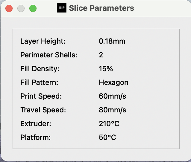
Figure: FlashPrint Slice Parameters documenting the layer height, perimeter shells, fill density, fill pattern, print speed, travel speed, extruder temperature, and platform temperature used to prepare the model.
Reviewing the Sliced Model
After slicing the model, I reviewed the layer preview in FlashPrint. The slicing process generated 33 individual layers. Reviewing the layers was an important step because I needed to determine when to pause the printer and introduce the tulle fabric into the printing process.
The FlashPrint preview estimated a total print time of 2 hours and 11 minutes and approximately 6.00 meters of filament.
During the active printing process, the FlashPrint printer status panel displayed an extruder reading of 225/225°C and a platform reading of 100/100°C. These values document the temperatures displayed by the printer during the active print. The original Slice Parameters associated with the sliced model recorded 210°C for the extruder and 50°C for the platform.
Figure: FlashPrint layer preview and live printer status during the 3D printing process. The model was sliced into 33 layers with an estimated print time of 2 hours and 11 minutes.
Exporting and Sending the File to the 3D Printer
After positioning the model and confirming the slicing parameters, I prepared the file for the FlashForge Voxel printer.
The following process was used:
- Opened the 3D model in FlashPrint.
- Positioned and scaled the model on the virtual print bed.
- Opened the slicing settings and reviewed the print parameters.
- Sliced the model using a 0.18 mm layer height, two perimeter shells, 15% fill density, and a hexagon fill pattern.
- Reviewed the 33-layer preview to identify the point where the tulle fabric would be added.
- Prepared the sliced model as a
.gxfile. - Saved the
.gxfile and sent the printer-ready file to the FlashForge Voxel. - Started the print and carefully monitored the completion of the first three layers.
The .gx file contained the sliced toolpath and printer instructions needed to fabricate the model. Reviewing the layer preview before sending the file to the printer was especially important because this experiment required me to manually pause the printing process and add the textile at a specific point.
3D Printing Process
Adding the Tulle to the 3D Print
I allowed the printer to complete the first three layers directly on the print bed. These initial layers created the lower foundation of the 3D-printed structure. After the third layer was completed, I paused the 3D printer before the next layers were deposited. I carefully placed a piece of tulle fabric over the partially printed structure. I stretched the tulle across the print bed and kept the fabric as flat and smooth as possible. The fabric was placed under light tension to reduce wrinkles and prevent it from lifting into the path of the print nozzle. I secured the outer edges of the tulle to the print platform so that the textile would remain in position when the printer resumed. The secured areas were kept outside the active printing area and away from the movement path of the print head.
This step was particularly important because loose tulle could lift, shift, or catch on the heated nozzle. Before restarting the printer, I visually checked the fabric to make sure it was flat and that the print head had a clear path of movement. Once the tulle was correctly positioned and secured, I resumed the print.
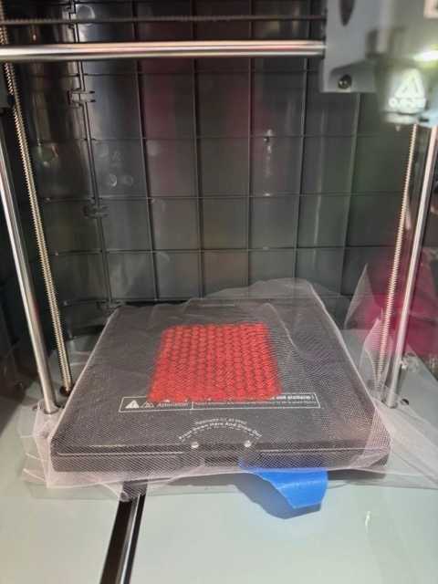
Figure: Tulle fabric positioned and secured over the print bed after the first three layers of the 3D model were completed.
Printing Directly onto the Tulle
After the printer resumed, the remaining layers were deposited directly over the tulle fabric. Because tulle has an open mesh structure, the heated filament was able to interact with the openings in the textile. The upper printed layers connected with the previously printed lower layers through portions of the mesh. This process effectively sandwiched the tulle between the lower and upper layers of the 3D print. Rather than gluing or sewing the printed object onto the textile after fabrication, the textile became physically integrated into the structure during the additive manufacturing process. The open structure of the tulle helped create a mechanical connection between the textile and the printed form.
3D Printing on Tulle
Final Result
The final model demonstrated a successful combination of additive manufacturing and textile fabrication. The tulle became integrated into the 3D-printed structure rather than simply being attached to the surface after printing. This experiment demonstrated how 3D printing can be used to create structured elements directly on flexible textiles. The open mesh of the tulle provided spaces for the printed material to connect between the lower and upper layers of the model. It also demonstrated the importance of slicing parameters, layer planning, printer pausing, textile positioning, and fabric tension when printing directly onto a textile.
One of the most important lessons from this process was the need to carefully plan the layer at which the textile would be introduced. Printing the first three layers created a foundation for the model, while the remaining layers secured the tulle within the printed structure. This technique provides opportunities for future experimentation with 3D-printed textiles, wearable structures, and digitally fabricated fashion applications.
3D Design and Fabrication Files
The following files document the development of my 3D star node design. The STL file can be opened in 3D printing and slicing software, while the Blender file contains the editable 3D model.
3D Model Files
The following files document the development of my 3D star node model.
STL File
The STL file contains the printable 3D model and can be opened in 3D appropriate software.
Blender File
The Blender file contains the editable 3D model and can be opened in Blender.