10. Textile Scaffold
Research

Image courtesy of Isobel Jo Leonard from Fabricademy
Textile scaffold is a term used in material science, bioengineering, and advanced fashion/tech design. It refers to a fabric-based structure engineered to support, shape, or grow something else. Depending on the field, it has two major meanings:
-
Textile Scaffold in Tissue Engineering (Biotechnology) In biomedical science, a textile scaffold is a woven, knitted, braided, or nonwoven fabric structure designed to help human cells grow. Scientists use textile scaffolds as artificial support systems for building or repairing biological tissues. The purpose of this type of scaffold is (1) Allow cells to attach and multiply, (2) Guide tissue formation (skin, cartilage, tendons, blood vessels), (3) Provide strength + flexibility, and (4) Eventually biodegrade as natural tissue replaces it. Common materials used are: • Collagen • Silk fibroin • PLA, PGA (biodegradable polymers) • Gelatin • Electrospun nanofibers Which can be used in regenerative medicine, wound healing, artificial organs, and biomanufacturing research.
-
Textile Scaffold in Fashion & Material Design In fashion, avant-garde design, and soft robotics, a textile scaffold refers to a fabric-based framework that provides structure, shape, or function to an engineered garment. It’s like the “skeleton” or “architecture” of an advanced textile system. This type of scaffold (1) Maintain shape, (2) Guide air flow or expansion, (3) Support movement, and (4) Allow integration of sensors, electronics, or biomaterials. Textile Scaffold in Fashion and Material Design can be used in: • Inflatable garments (air channels rely on textile scaffolds) • Soft robotic clothing • 3D-printed-on-textile hybrids • Shape-changing garments • Biofabricated or grown materials • Experimental couture (with designers such Iris van Herpen, Neri Oxman)
References & Inspiration
There was a lot of inspiration with the textile scaffold. I am instantly gravated towards the leather molding but using the leather as some sort of origami because you can create the mold of itself. This can be a great technique because the leather folds develop structural memory due to molding and the folds become stronger, architectural, and self-supporting.
- Origami


Reference: Image: via plieproject
Crystals have long symbolized transformation, clarity, and creativity—and DIY borax crystals bring that magic into an accessible, hands-on design experience. When paired with jewelry-making techniques, borax crystals become shimmering, sculptural elements that elevate even the simplest designs. Crystals at home using borax/alum/epson salt/sugar, hot water, and pipe cleaners, watching as geometric forms slowly emerge overnight. These handmade crystals can then be wire-wrapped, turned into pendants, attached to chains, or embedded in resin to create unique, personalized accessories. The beauty of DIY borax crystals is their unpredictability—each piece forms a different shape, texture, and sparkle, mirroring the individuality of every designer. By combining the natural-looking crystalline structures with the limitless possibilities of borax crystal growth, students are encouraged to explore material alchemy, embrace experimentation, and transform everyday ingredients into wearable art. This fusion of science and style not only introduces students to jewelry design, but also ignites curiosity, confidence, and creativity.

Image courtesy Doja Cat in British Vogue
Process and workflow
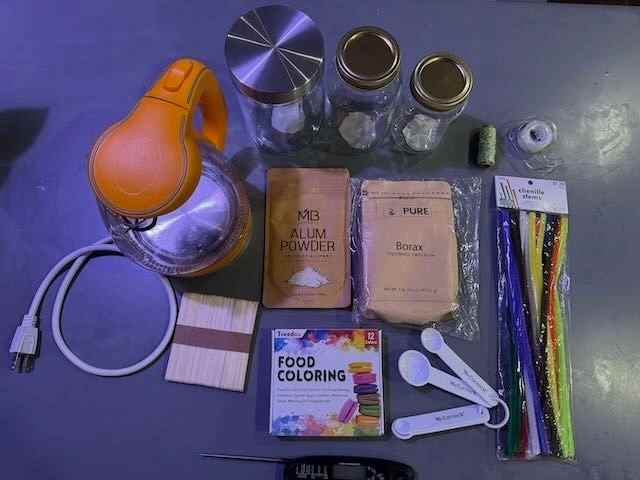
My first step was to create crystals from Alum and Borax.....
DIY Crystals
Prepare this recipe [^1] by collecting the ingredients necessary, to be found in the list below:
=== "ingredients"

    * 40 gr of Alum
    * 100 ml of H2O
    * pipe cleaner
    * popsicle stick
    * string
    * tape

40 grams of Alum was water that was simmering but not boiling. The Alum was added a little at a time until it became cloudy. The mixture was extruded through a coffee filter. I like to create personalized products; therefore, I used a pipe cleaner to create my daughter's initial, which is a N. I added the pipe cleaner to a string and tape it on a popsicle stick to be placed across the jar with a coffee filter on top to prevent any contamination in the jar. The solution sat overnight. The next day crystals were formed and was use to create an earring for my daughter Navy.
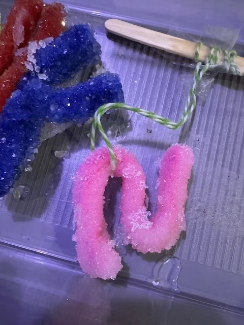

=== "ingredients"

    * 4 tablespoon of Borax
    * 2 cups of H2O
    * pipe cleaners
    * popsicle stick
    * string
    * tape
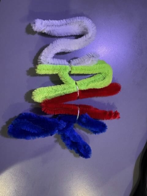
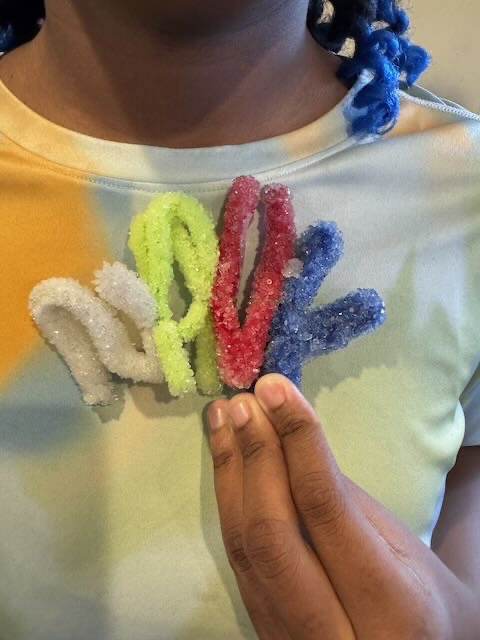
4 tablespoon of Borax was added to 2 cups of simmering not boiling water. The Borax was added one tablespoon at a time until the solution was saturated and no longer clear. The solution was filtered through a coffee filter. I used a series of pipe cleaners to make a name plate for my daughter Navy. The letters were formed and put together by string. The string was taped on a popsicle stick and sat overnight with a coffee filter on top of the jar.

Leather Molding

The Process:
- A piece of brown leather was used for to determine if it can be mold in an origami form within itself.
- I took the leather and placed it in a clear container of warm water for 30 minutes until it became soft and pliable.
- After 30 minutes, the leather was sqeeze between a towel to remove excess water.
- Next, I started working on the shape of the leather by creating v-shape folding.
RESULTS


CNC Milling: Creating a Wooden Bracelet Mold
This was my first experience using a CNC milling machine. My goal was to create a wooden mold that could be used to explore leather molding and the development of a flexible bracelet form.
Designing the Flexible Bracelet File
I began with a flexible bracelet design composed of repeated elongated shapes and circular openings. The design was prepared as a vector file and saved in .svg format for digital fabrication.
The SVG file was imported into VCarve, the Vectric software used to prepare the design for CNC machining. VCarve allows vector files to be positioned, edited, and converted into toolpaths that can be interpreted by the CNC machine.
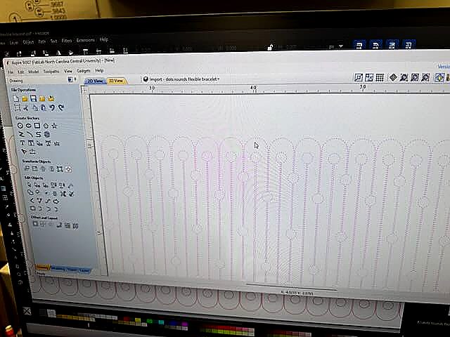
VCarve workspace showing the imported flexible bracelet SVG. The repeated vector shapes and circular openings are visible in the digital workspace before toolpath preparation.
Downloadable Fabrication File
The SVG file used for my CNC flexible bracelet experiment can be downloaded below:
Download the Flexible Bracelet SVG
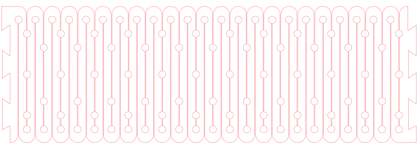
- File format: SVG
- Design: Flexible bracelet
- Digital fabrication process: CNC milling
- Software: VCarve
- Machine: ShopBot CNC
Preparing the CNC File
After importing the SVG into VCarve, I positioned the bracelet design within the digital workspace. The wood used for the experiment measured approximately 5.5 inches wide by 9 inches long.
The vector geometry was reviewed before the CNC machining process. The repeated shapes in the bracelet design were intended to explore how cuts in a rigid material could be used to develop a flexible or segmented form.
Loading the CNC File
The prepared CNC file was loaded into the ShopBot control software. The ShopBot controller communicates the machining instructions to the CNC router.
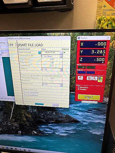
ShopBot CNC controller showing the Part File Load window and machine position interface. The X, Y, and Z coordinates are displayed before beginning the CNC operation.
The X, Y, and Z coordinates shown in the controller represent the position of the CNC cutting tool. The controller was used to prepare the machine and load the cutting file before starting the machining process.
ShopBot CNC Controller
The ShopBot Command Console displayed the CNC machining instructions while the cutting file was running.
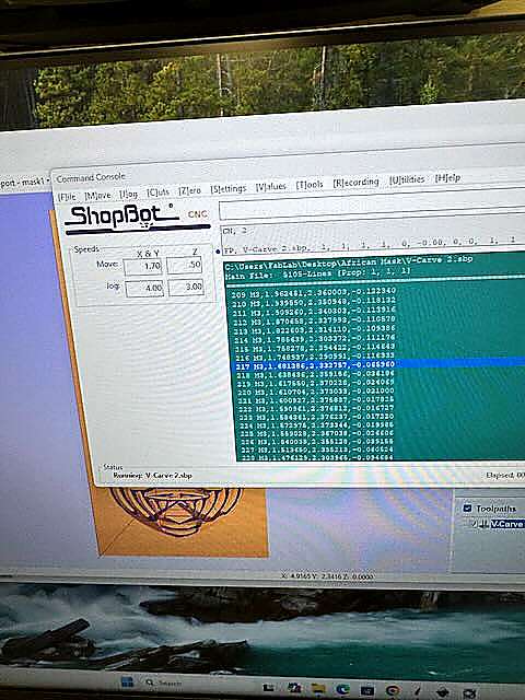
ShopBot Command Console displaying the active VCarve machining file and CNC movement commands during the milling process.
The command console displayed the machine instructions generated from the VCarve file. These numerical commands controlled the movement of the CNC router along the X, Y, and Z axes.
CNC Milling in Progress
Once the CNC file was loaded and the machine was prepared, the ShopBot began following the programmed toolpath.
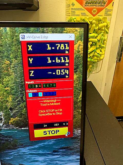
ShopBot CNC controller during active machining. The X, Y, and Z coordinates changed as the cutting tool moved through the programmed toolpath. The controller also displayed the warning "Tool in Motion!" while the machine was operating.
The changing X, Y, and Z coordinates allowed me to observe the movement of the cutting tool during the CNC milling process.
First CNC Milling Result: Failed Mold
The first CNC milling experiment was unsuccessful.
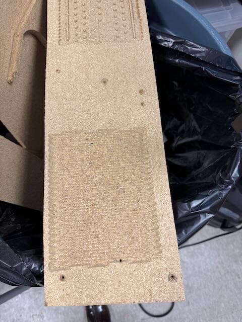
I believe one of the primary problems was my choice of material. I used particle board, which did not produce the clean and stable mold that I expected. The material began to break apart and did not maintain the details of the bracelet design.
This failure helped me understand that material selection is an important part of CNC fabrication. If I repeated this experiment, I would select a more stable material that is better suited for CNC machining and mold fabrication.
Iteration: African Mask as a Leather Mold
Instead of ending the experiment after the failed bracelet mold, I decided to continue exploring the relationship between CNC-fabricated forms and leather molding.
I used an African mask that had been created on the milling machine as an alternative three-dimensional mold.
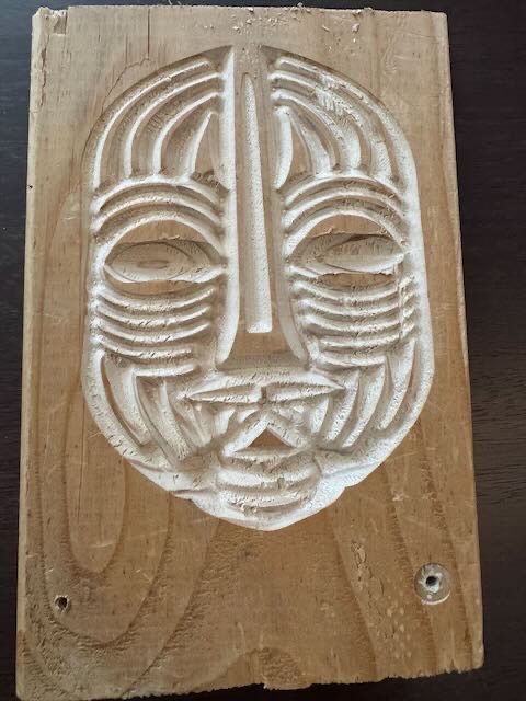
The dimensional facial features of the African mask provided a more defined surface for testing the wet leather molding process.
Preparing the Leather
A piece of shimmer-finished leather was placed in warm water for approximately 45 minutes. The warm water softened the leather and made the material more pliable.
After soaking, I removed the excess water and carefully stretched and formed the leather around the wooden African mask.
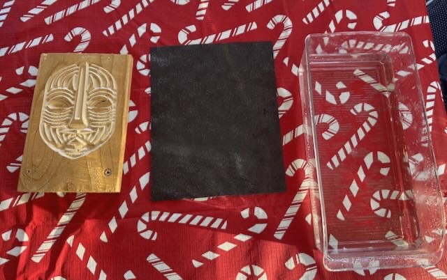
The leather-covered mask was then placed under pressure overnight so that the leather could dry around the three-dimensional form.
Final Result
The leather retained the dimensional features of the African mask and created a recognizable molded surface.


The side-by-side comparison demonstrates how the wet leather captured the primary contours and facial features of the African mask.
Reflection
This experiment allowed me to explore the relationship between digital design, CNC milling, material selection, and leather molding.
My first attempt to create a wooden bracelet mold was unsuccessful; however, the failed experiment became an important part of my learning process. I learned that a digital design and CNC toolpath alone do not guarantee a successful fabrication result. The physical properties of the material must also be considered.
I adapted my process by using a CNC-milled African mask as a three-dimensional leather mold. The mask produced a much stronger result because its raised and recessed features created a defined surface for forming the wet leather.
The African mask was also my favorite part of this experiment because it connected digital fabrication with my interest in African-inspired design and wearable art. This process inspired me to continue exploring how culturally inspired forms can be combined with digital fabrication and traditional textile and leather techniques.