9. Wearables
Research
Photo from ELE Times
Wearables are technologies designed to be worn on or near the body that integrate electronics, sensors, and digital systems to support interaction, monitoring, communication, or expression. In fashion and textile contexts, wearables often take the form of garments, accessories, or body-adjacent materials that combine traditional textiles with soft electronics, conductive materials, and embedded systems. Designers and researchers use wearables to explore areas such as health monitoring, movement tracking, performance enhancement, and interactive or expressive design. Beyond functionality, wearables also raise important questions about comfort, identity, ethics, and embodiment, encouraging designers to think critically about how technology can be integrated into everyday life in ways that are human-centered, culturally meaningful, and responsive to the body.
References & Inspiration
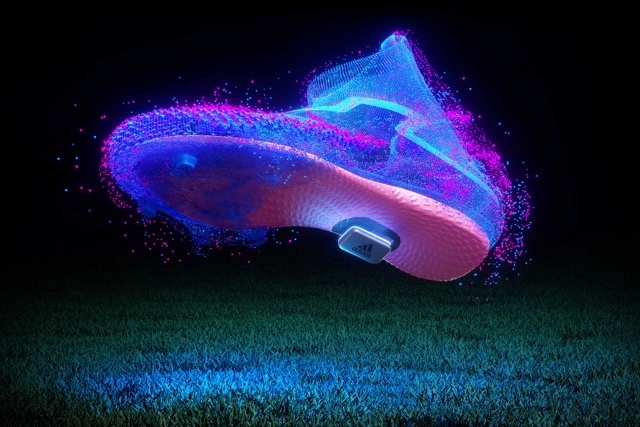
Adidas x Google
Adidas x Google Jacquard is a collaboration that demonstrates how computational textiles can be embedded seamlessly into everyday sportswear. Using Google’s Jacquard technology, conductive yarns are woven directly into the fabric of a jacket sleeve, turning the textile itself into a touch-sensitive interface. Rather than adding visible hardware, the technology remains soft, flexible, and wearable, preserving comfort and aesthetics. The Jacquard sleeve allows users especially cyclists and urban commuters to control music, navigation, and phone functions through simple gestures such as tapping or swiping the fabric. This approach shifts wearable technology away from screens and buttons, emphasizing gesture-based interaction and intuitive use. The project highlights how wearables can enhance performance and safety while remaining unobtrusive. As an example of applied wearable design, Adidas x Google Jacquard bridges fashion, athletics, and human–computer interaction, showing how textiles can function as active interfaces. It serves as a key inspiration for computational couture and e-textiles by proving that smart garments can be scalable, functional, and integrated into real-world use.
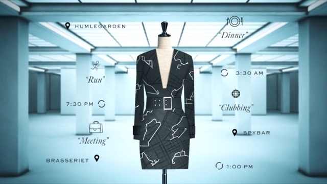
Ying Gao
Ying Gao is a Montréal-based fashion designer and researcher whose work focuses on interactive, responsive garments that react to human presence, gaze, sound, and movement rather than direct touch. Her practice sits at the intersection of fashion, technology, philosophy, and performance, using wearables to question how the body communicates with its environment. Unlike many wearable designers who emphasize screens or LEDs, Gao’s garments often rely on subtle mechanical movement, such as unfolding, vibrating, inflating, or shifting surfaces. Using sensors, microcontrollers, and soft actuation, her designs respond when a viewer looks at the garment or speaks near it making the act of observation part of the interaction. This creates a quiet but powerful form of responsiveness that challenges traditional ideas of fashion as static or purely decorative. Gao frequently collaborates with engineers, programmers, and sound artists, and her work is deeply influenced by research and critical theory. Rather than designing for mass production, she treats wearables as experimental interfaces, exploring themes of intimacy, surveillance, perception, and emotional response. Her projects blur boundaries between clothing, installation, and living system.
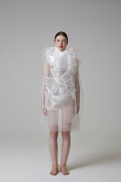 Photo from yinggao.ca
Tools
Two Actuator Swatches
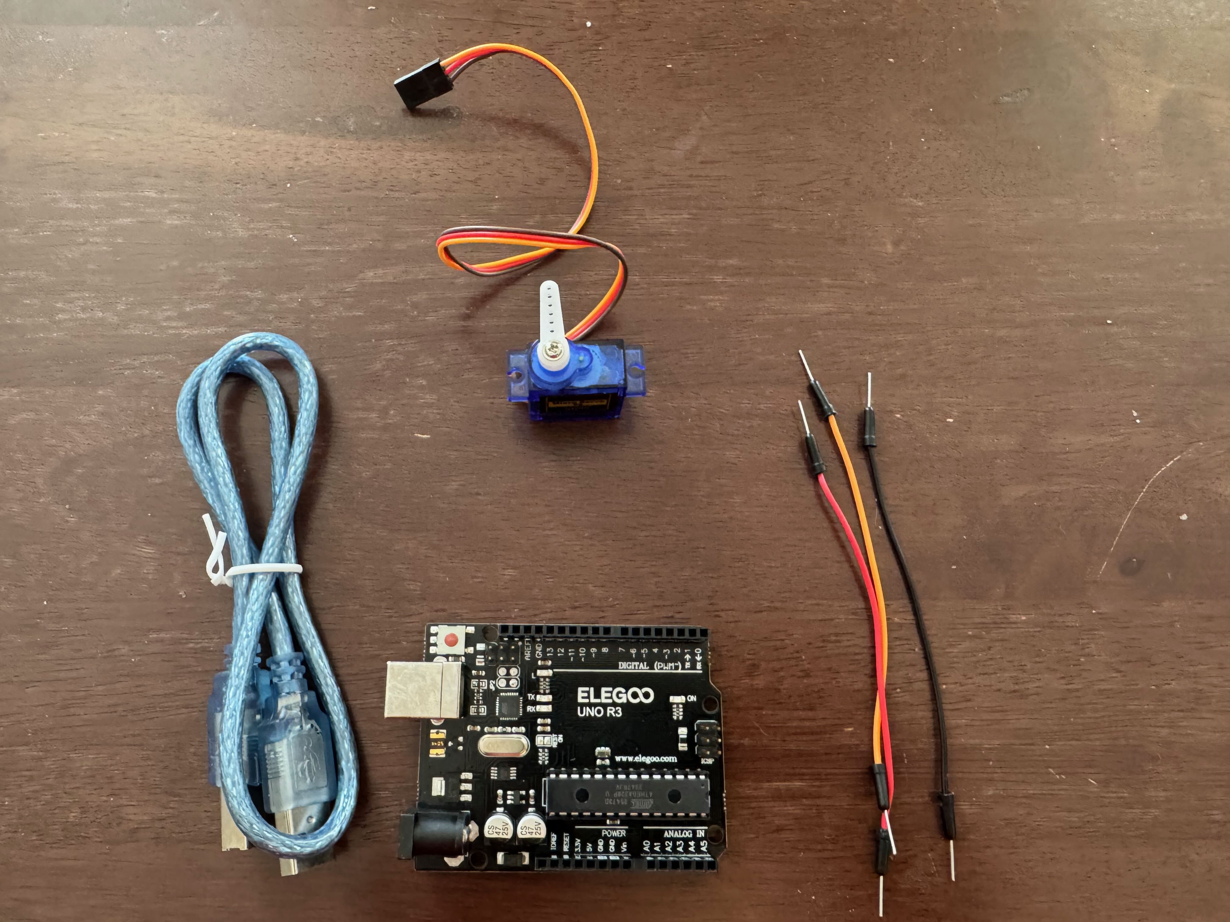
For this assignment, I created and tested two distinct actuator swatches: a servo motor and an LED light sequence. The servo motor demonstrates controlled mechanical movement. By programming the servo to rotate to specific angles, I explored how movement could be incorporated into a textile or wearable design. For my Botanical Crown project, this type of actuator could potentially move, lift, or reposition textile hair structures. The LED actuator demonstrates programmed illumination and visual communication. The sequence of LEDs creates a changing light pattern controlled by the microcontroller. In an Afrocentric wearable design, programmed light could potentially communicate mood, rhythm, identity, or cultural symbolism. Together, the two actuator tests demonstrate two different forms of physical computing output: movement and illumination.
Servo motor
Schematic
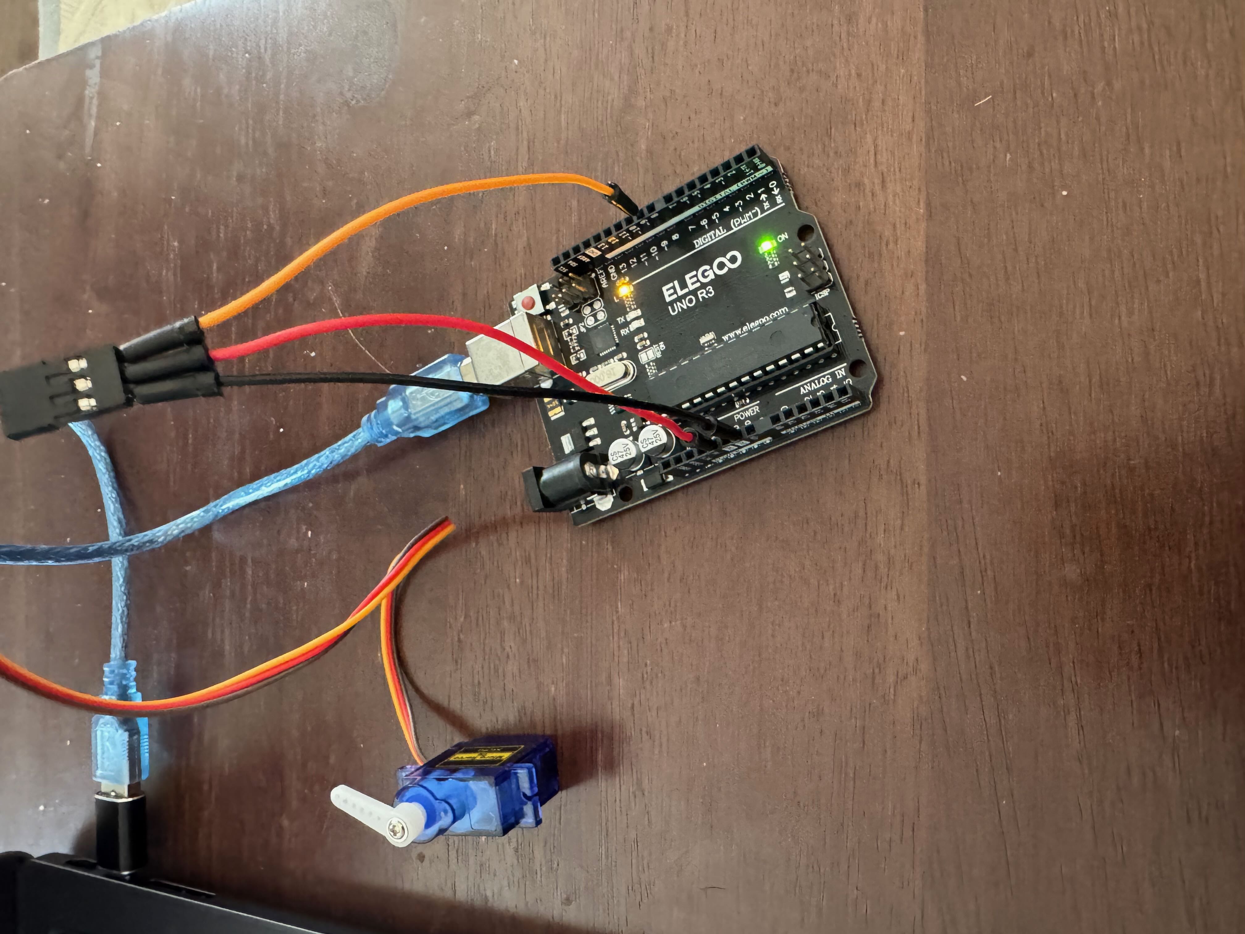
Using the Arduino IDE with an Elegoo UNO R3 to control a servo motor involves setting up a simple hardware connection and uploading a sketch that sends position commands to the servo. First, the servo is wired to the UNO R3: the red wire connects to 5V, the brown or black wire to GND, and the yellow/orange signal wire to a digital PWM pin (commonly pin 9). This allows the microcontroller to send control pulses that determine the servo’s angle. In the Arduino IDE, the Servo library is used to simplify control. After selecting Board → Arduino Uno and the correct Port, a sketch is written that attaches the servo to the chosen pin and sets its position using degree values (0–180). When the code is uploaded, the servo responds by rotating to the specified angles. This process demonstrates how the Arduino IDE translates simple code into physical movement, reinforcing core concepts such as library usage, pin assignment, and PWM-based control. It serves as an essential foundation for projects involving motion, robotics, and interactive systems. A servo motor can be controlled using the Elegoo UNO R3 and the Arduino IDE by sending precise position commands through a digital PWM pin. This setup is commonly used in robotics, kinetic design, and interactive systems where controlled movement is required.
The servo has three connections: • Red → 5V (power) • Brown/Black → GND • Yellow/Orange → Digital PWM pin (commonly pin 9)
In the Arduino IDE, the built-in Servo library is used to manage timing and pulse signals automatically. After selecting Board: Arduino Uno and the correct Port, the code is uploaded to the board. The servo is then instructed to rotate to specific angles between 0° and 180°.
Basic Servo Sweep Code (Arduino IDE)
Servo Motor Code
#include <Servo.h>

Servo myServo;

const int servoPin = 9;

void setup() {
  myServo.attach(servoPin);
}

void loop() {
  myServo.write(0);
  delay(1000);

  myServo.write(90);
  delay(1000);

  myServo.write(180);
  delay(1000);
}
The Arduino Servo library was used to control the servo motor. The servo signal wire was connected to digital pin 9. The program rotates the servo between 0°, 90°, and 180°, demonstrating controlled mechanical movement.
leds
Servo Motor Visual Diagram
The following Tinkercad diagram shows the complete connection between the Elegoo UNO R3 and the servo motor.
LED Light Sequence Actuator
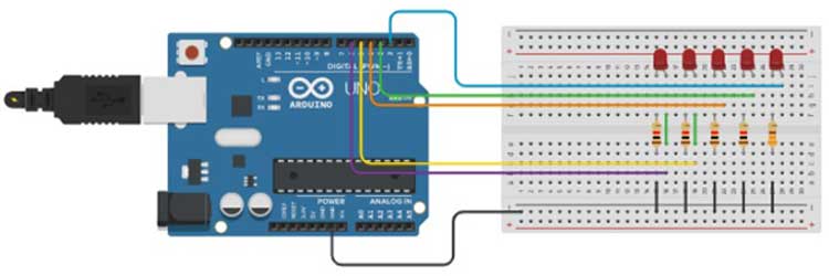
The second actuator experiment uses eight LEDs controlled through a 74HC595 shift register. The shift register allows the Arduino UNO to control multiple LED outputs using three microcontroller pins. The Arduino sends data to the 74HC595 through the data, clock, and latch connections. The shift register then controls the eight LED outputs.
74HC595 Connection Schematic
Arduino UNO                 74HC595
-----------                 -------
5V  ---------------------- 16 (VCC)
GND ----------------------  8 (GND)

D12 (dataPin) ------------ 14 (DS / SER)
D9  (clockPin) ----------- 11 (SH_CP / SRCLK)
D11 (latchPin) ----------- 12 (ST_CP / RCLK)

5V  ---------------------- 10 (MR / SRCLR)
GND ---------------------- 13 (OE)

LED Outputs:

15 (Q0) → 220 Ω resistor → LED → GND
1  (Q1) → 220 Ω resistor → LED → GND
2  (Q2) → 220 Ω resistor → LED → GND
3  (Q3) → 220 Ω resistor → LED → GND
4  (Q4) → 220 Ω resistor → LED → GND
5  (Q5) → 220 Ω resistor → LED → GND
6  (Q6) → 220 Ω resistor → LED → GND
7  (Q7) → 220 Ω resistor → LED → GND
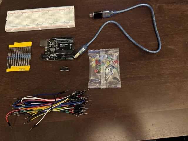
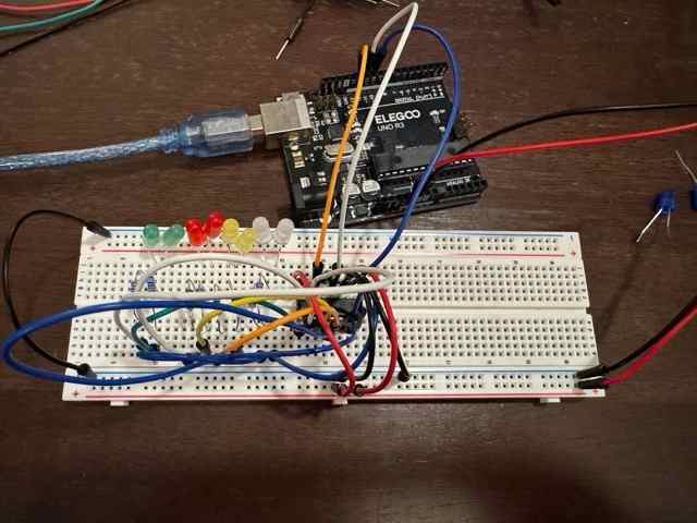
The first image documents the materials stage: an Elegoo Uno R3 microcontroller, breadboard, USB cable, resistors, jumper wires, and a mixed LED kit. This is the preparation phase where all components are organized before building the circuit. The second image shows the assembled circuit. Multiple LEDs are wired in a row on the breadboard, each connected through resistors and jumper wires to the Arduino. The board is powered via USB and appears to be running a test program, likely for LED sequencing or blinking. This setup demonstrates basic circuit principles: power distribution, grounding, resistor protection for LEDs, and digital output control from the microcontroller. Overall, the photos capture the transition from component layout to a functioning prototype, illustrating foundational skills in Arduino wiring, breadboarding, and LED control.
LED Light Show Code (Arduino IDE)
//www.elegoo.com
//2016.12.9

int tDelay = 100;
int latchPin = 11;      // (11) ST_CP [RCK] on 74HC595
int clockPin = 9;      // (9) SH_CP [SCK] on 74HC595
int dataPin = 12;     // (12) DS [S1] on 74HC595

byte leds = 0;
/*   The most common method of using 74CH595
 *   lctchPin->LOW : Begin transmitting signals.
 *   shiftOut(dataPin, clockPin, bitOrder, value)
 *   dataPin: the pin on which to output each bit. Allowed data types: int.
 *   clockPin: the pin to toggle once the dataPin has been set to the correct value. Allowed data types: int.
 *   bitOrder: which order to shift out the bits; either MSBFIRST or LSBFIRST. (Most Significant Bit First, or, Least Significant Bit First).
 *   value: the data to shift out. Allowed data types: byte.
 *   lctchPin->HIch : The end of the transmission signal.
*/
void updateShiftRegister()
{
   digitalWrite(latchPin, LOW);
   shiftOut(dataPin, clockPin, LSBFIRST, leds);
   digitalWrite(latchPin, HIGH);
}

void setup()
{
  pinMode(latchPin, OUTPUT);
  pinMode(dataPin, OUTPUT);
  pinMode(clockPin, OUTPUT);
}

void loop()
{
  //Turn off all led
  leds = 0;
  updateShiftRegister();
  delay(tDelay);
  //Create a for loop:i 0 through 7 have gradually increased
  for (int i = 0; i < 8; i++)
  {
    //turn on the led with the i transform
    bitSet(leds, i);
    updateShiftRegister();
    delay(tDelay);
  }
}
Wearable Interactive Plushie
Concept and Design
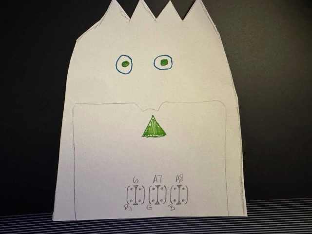
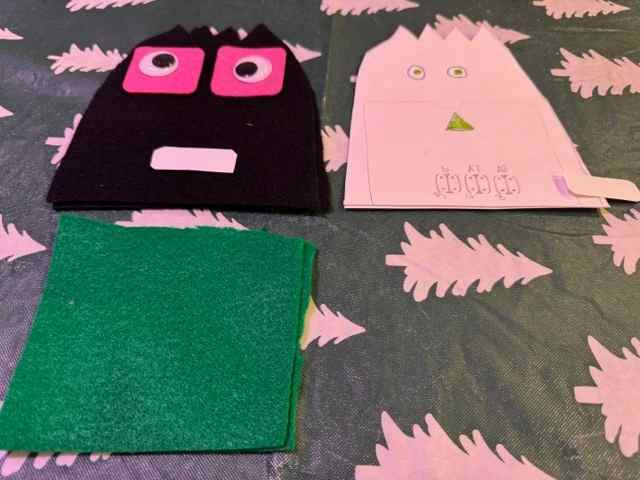
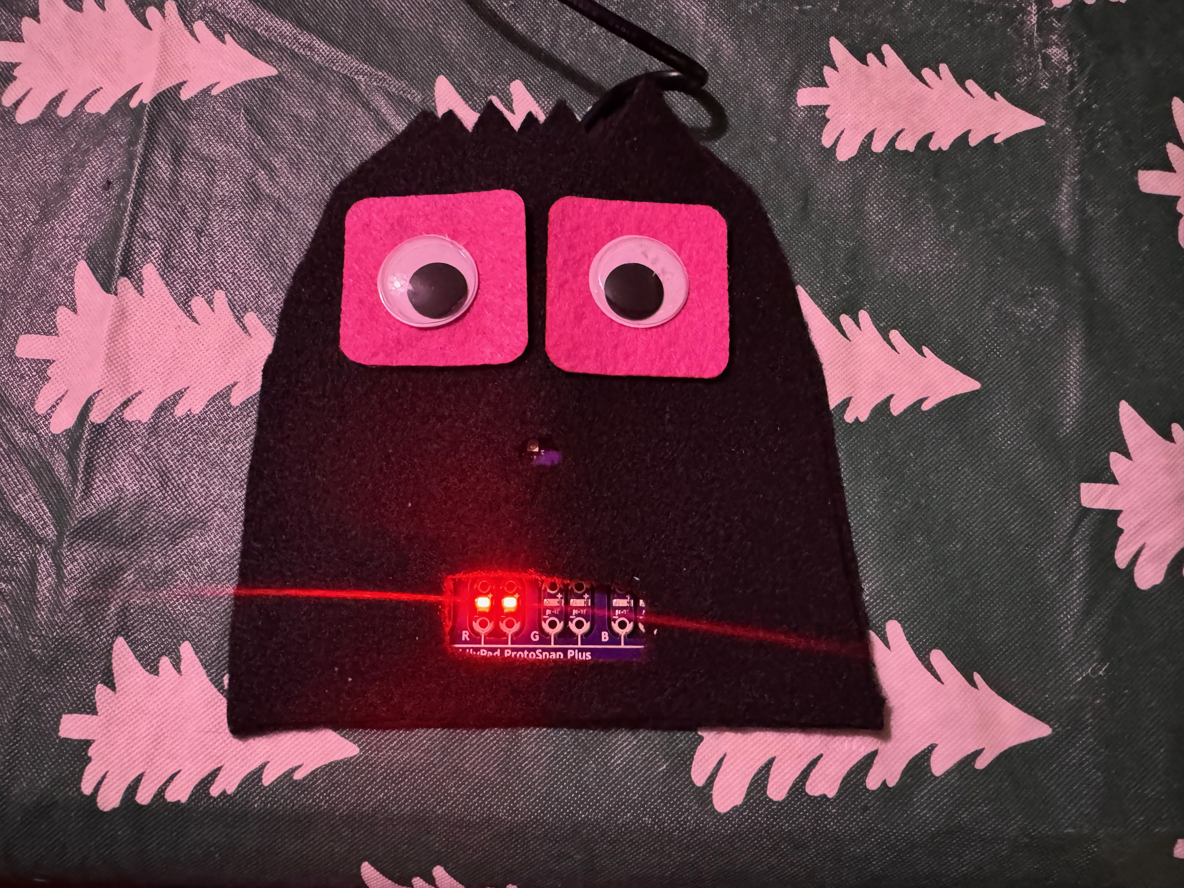
For the Wearables assignment, I created a soft textile plushie that integrates a LilyPad ProtoSnap Plus microcontroller and programmable LED light outputs into a felt structure. This plushie is a separate project from my earlier Velostat pressure sensor experiments. The concept began with a hand-drawn character design. I planned the shape of the plushie, facial features, and approximate placement of the electronic components before cutting the textile materials. The sketch includes labeled positions for the LilyPad ProtoSnap Plus LED pins, showing my early planning for light output and electronic component placement. The paper pattern was used to establish the shape and dimensions of the plushie. The pattern was then transferred to felt and used to cut the textile layers.
LilyPad ProtoSnap Plus and Programmed LED Output
The LilyPad ProtoSnap Plus was used as the microcontroller for the plushie. The Arduino code automatically sequences the programmed LED outputs. No physical sensor was used to trigger the color changes in this plushie. Instead, the program uses timed delays and a for loop to move through the assigned LED pins. Each programmed output turns on and off according to the sequence written in the Arduino sketch.
The system follows this programmed sequence:
ARDUINO CODE
      ↓
LILYPAD PROTOSNAP PLUS
      ↓
PROGRAM EXECUTES LED SEQUENCE
      ↓
LED OUTPUTS TURN ON AND OFF
      ↓
VISIBLE LIGHT CHANGES IN THE PLUSHIE
The LilyPad ProtoSnap Plus functions as the microcontroller, while the LEDs function as the actuator or output.
Integrating Electronics into the Textile
The electronic components were incorporated directly into the felt structure rather than remaining as a separate breadboard experiment. Openings in the front textile layer allowed the LED light and portions of the LilyPad ProtoSnap Plus to remain visible. The LilyPad components were positioned within the lower section of the plushie. This placement allowed the electronic system to become part of the textile design while still providing access to the board during programming and testing. The felt represents the soft textile material, while the LilyPad and LED components represent the rigid electronic elements. Combining these materials allowed me to explore hard-soft connections in e-textiles and consider how electronics can be physically incorporated into a soft object.
Uploading the Program
The Arduino sketches were uploaded through the Arduino IDE by connecting the board with USB, selecting the appropriate board and serial port, compiling the sketch, and selecting Upload.
The complete upload process was previously documented during my E-Textiles assignment:
View the Arduino upload process from E-Textiles
Test Code
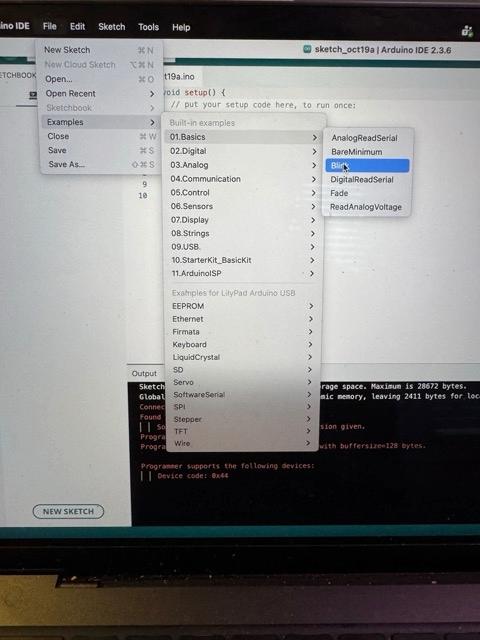
The Arduino IDE Blink test was used to verify basic functionality of the LilyPad ProtoSnap Plus before integrating it into a soft electronic swatch. The test confirms that the board is properly powered, recognized by the Arduino IDE, and capable of running uploaded code. Using the Arduino IDE, the LilyPad Arduino USB board was selected along with the correct serial port. A simple Blink sketch was uploaded to the ProtoSnap, targeting the onboard green LED (pin A7). The program turns the LED on and off at timed intervals, creating a visible blinking pattern.
When the LED blinked successfully, it confirmed: • Correct board and port selection • Successful code compilation and upload • Proper power delivery and microcontroller operation • Functional LED output pin
The example of the blink code is below.
// LilyPad ProtoSnap Plus - Blink Test

void setup() {
  pinMode(A7, OUTPUT);
}

void loop() {
  digitalWrite(A7, HIGH);
  delay(1000);

  digitalWrite(A7, LOW);
  delay(1000);
}
Programmed LED Sequence
The LilyPad ProtoSnap Plus was programmed to control multiple LED outputs in sequence. Rather than changing LED brightness through PWM, this program uses digitalWrite() to turn each programmed output on and off. Six LED pins were identified in an array. A for loop moves through each pin, turns the LED on for 400 milliseconds, turns it off, and then moves to the next output.
This experiment demonstrates:
- Controlling multiple outputs with a microcontroller
- Using arrays to organize Arduino pin assignments
- Using a
forloop to repeat programmed actions - Using
digitalWrite()to control HIGH and LOW output states - Translating Arduino code into a visible light sequence within a textile object
The LED sequence code is shown below.
int ledPins[] = {5, 6, 9, 10, 11, A7};

void setup() {
  for (int i = 0; i < 6; i++) {
    pinMode(ledPins[i], OUTPUT);
  }
}

void loop() {
  for (int i = 0; i < 6; i++) {
    digitalWrite(ledPins[i], HIGH);
    delay(400);

    digitalWrite(ledPins[i], LOW);
    delay(200);
  }
}
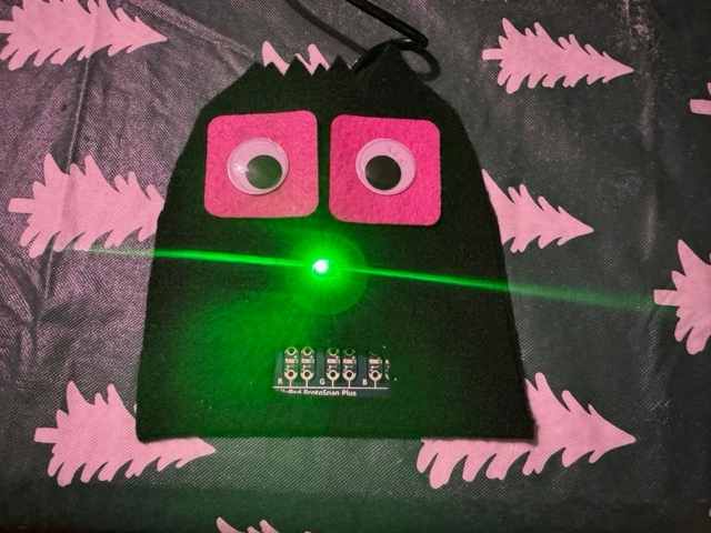
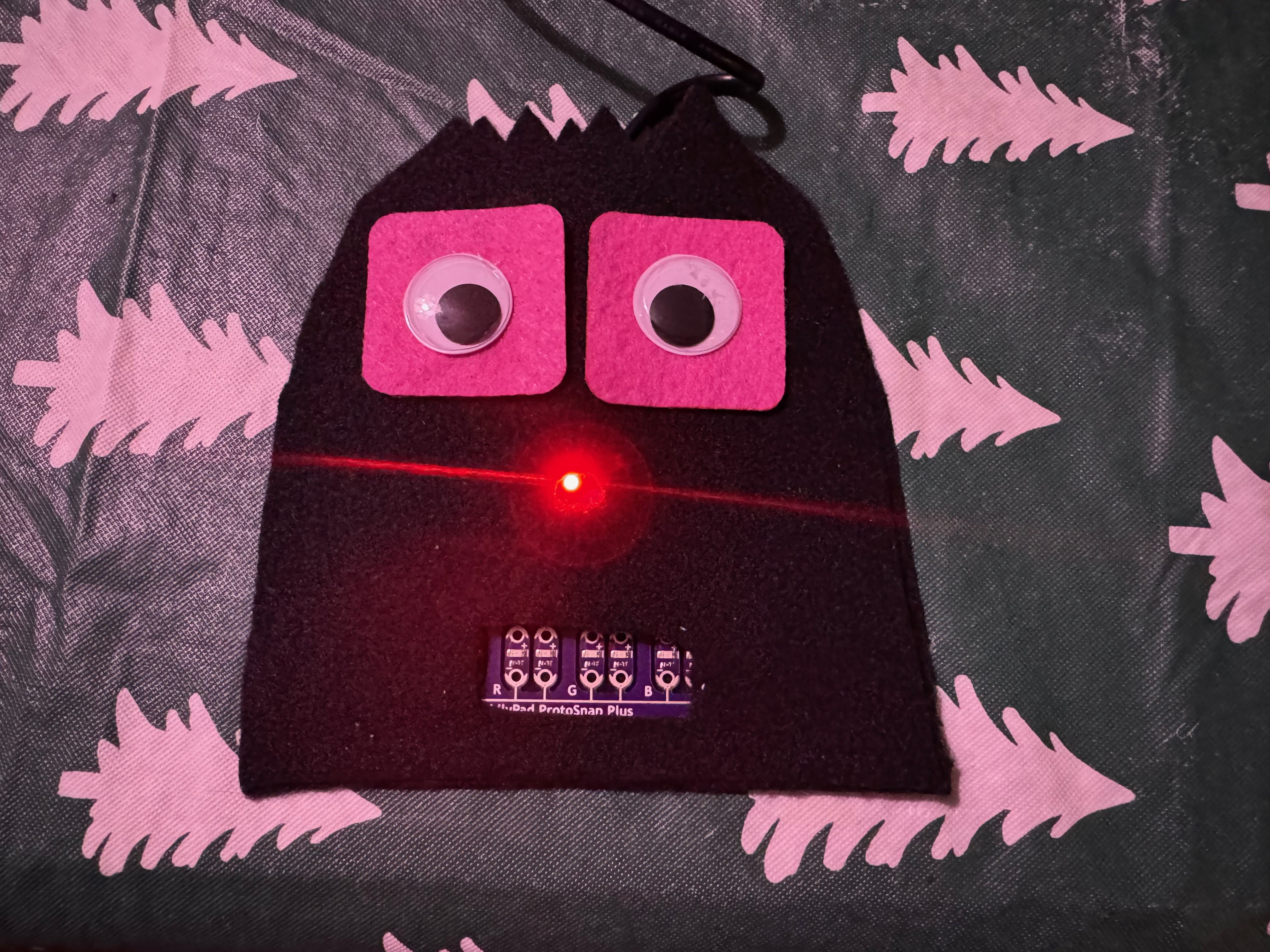
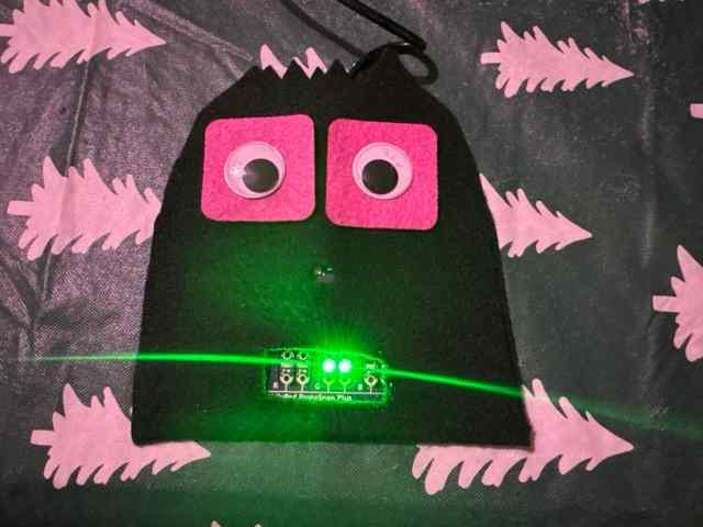
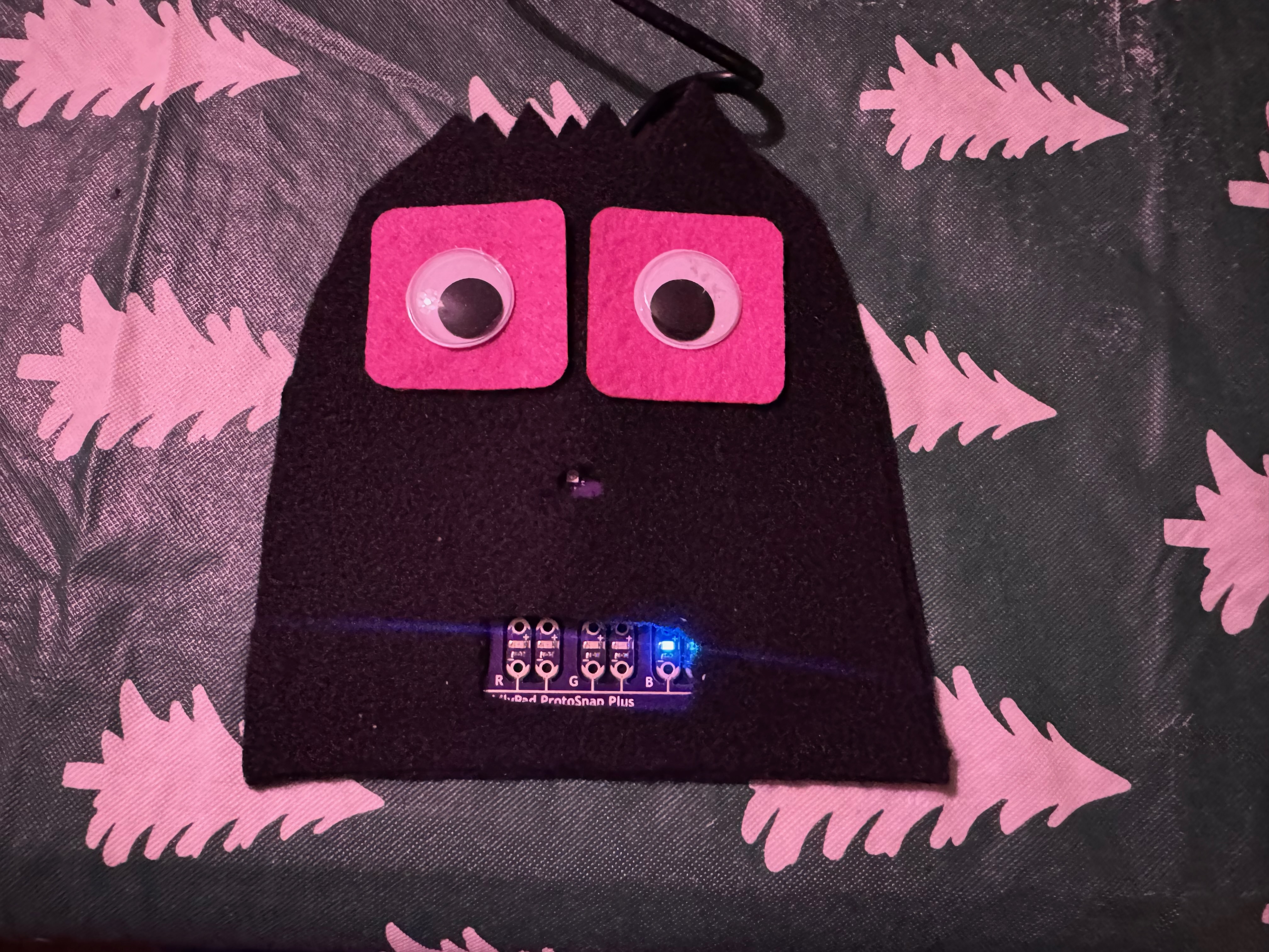
Testing the LED Outputs
The following photographs document the programmed light sequence during testing. The changing LED outputs confirmed that the LilyPad ProtoSnap Plus was receiving power, running the uploaded Arduino sketch, and controlling the light sequence. The completed plushie successfully integrated a LilyPad ProtoSnap Plus and programmable LED outputs into a soft felt structure. The Arduino program automatically controlled the LED sequence, producing visible changes in light within the textile object. This experiment helped me understand how a microcontroller can control multiple outputs through code. It also allowed me to explore component placement, hard-soft connections, and the integration of rigid electronic components into a flexible textile structure.
Video
From Youtube
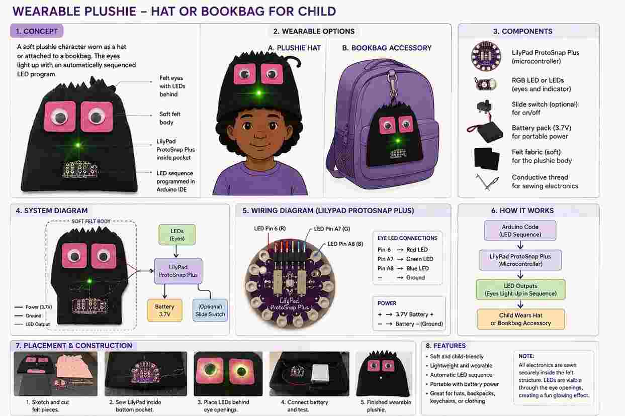
Wearable Plushie Design Concept and AI Visualization
The wearable plushie diagram explores how my original soft electronic plushie could be developed into a functional child-centered wearable. The character design could be incorporated into a soft hat or attached to a bookbag as an interactive accessory. The felt structure provides a lightweight and flexible textile surface, while the LilyPad ProtoSnap Plus serves as the microcontroller controlling the programmed LED outputs. Artificial intelligence (AI) was used as a design visualization tool during this process. I provided AI with photographs of my original handmade plushie prototype and described my idea of transforming the textile sample into a wearable product for a child. Using these design references and prompts, AI helped me visualize potential applications of the plushie as a wearable hat and an interactive bookbag accessory. The AI-generated diagram was not used to replace the physical prototype; instead, it was used as a conceptual development tool to explore how the original design could be adapted into future wearable applications. The diagram illustrates possible placement of the LilyPad, LEDs, power source, and conductive connections within the soft textile structure. The Arduino program automatically sequences the LED outputs, creating visible light changes in the plushie. A portable battery source could allow the design to operate independently from a computer, making the concept more appropriate for wearable use.
This AI-assisted design process helped me move from a physical textile experiment to a broader wearable concept. By combining hand sketching, physical prototyping, Arduino programming, textile fabrication, and AI visualization, I was able to explore potential applications for the plushie beyond the original swatch. The hat and bookbag concepts demonstrate how soft electronics and programmable light could be incorporated into playful, child-centered wearable designs.