5. E-textiles
Exploration
Throughout this week, we are exploring E-Textiles, which I understand as the systems where the electronics stop being an external element and become part of the textile structure. The main goal is to explore how a textile can conduct, feel or react, all while being flexible, soft and deformable.
Textiles protect and cover, while electronics speak in pulses, signals; In E-textiles these both worlds merge, the thread stops being structure and transports information, the stitch stops being a joint and becomes a circuit. Tech becomes soft and textile responds.
The emphasis is the material integration, not in electronics complexity. We are introducing electronics in the textile world through: * Integrating conductivity through threads or textile materials. * Creating flexible and functional circuits. * Develop sensors or actuators directly on the fabric. * Keeping the electrical functions under flexing and movement.
References & Inspiration
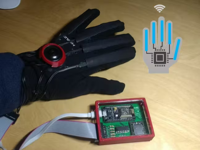
For this assignment I really wanted to experiment with this material called Velostat, which is a carbon-infused plastic that changes it's electrical resistance when flexing or stretching. I read about Gestr, a smart glove for speech impariments. It converts the finger movement into pre-programmed phrases.
Analog sensor
I figured i could experiment with Velostat for this part of the assignment.
Materials and tools
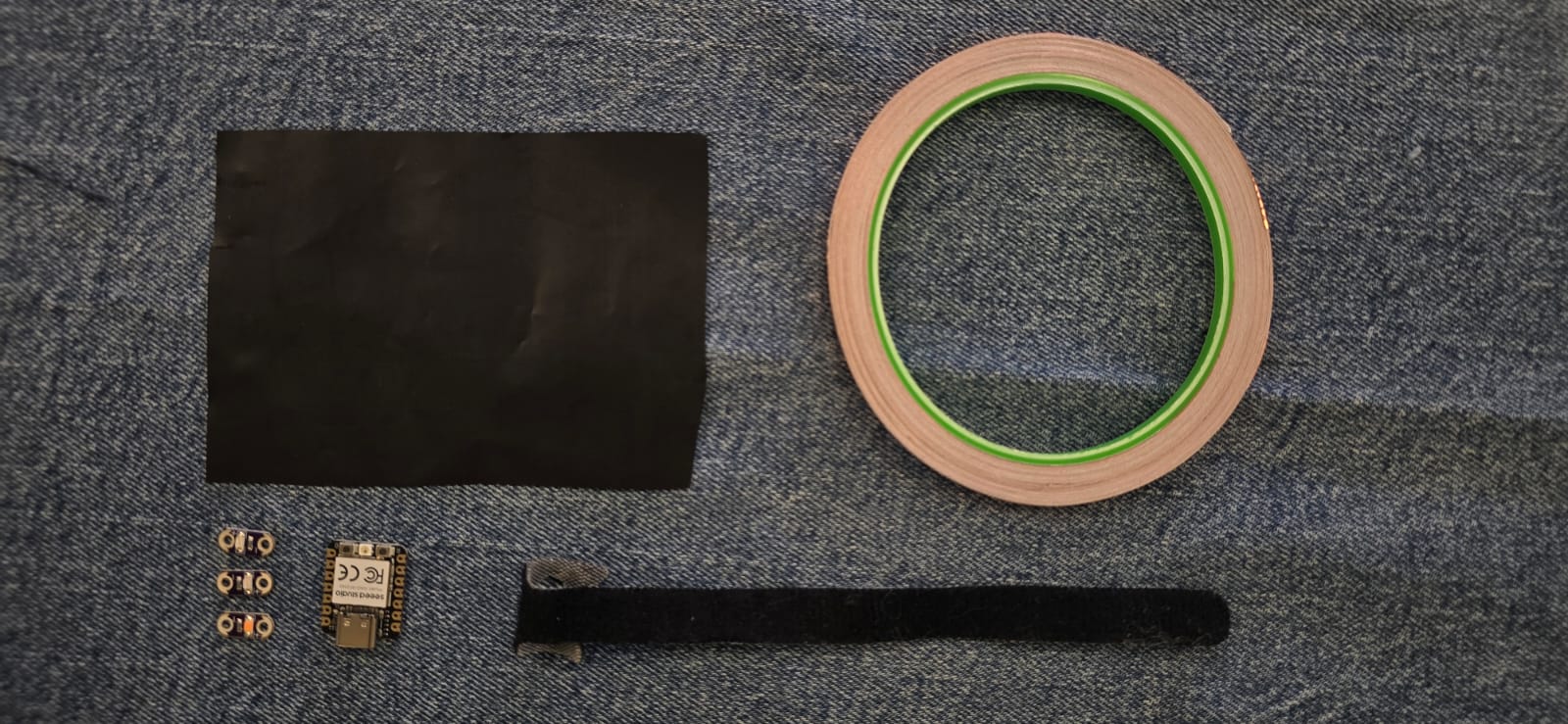
The materials and tools we need for this assignment are the following:
- A piece of Velostat
- A piece of cloth (i will be using denim)
- Conductive tape
- Xiao RP2040 Microcontroller
- Conductive thread
- 2 velcro cable straps
- 1 10kΩ resistor
- 3 LEDs: Green, yellow and red
Work Process
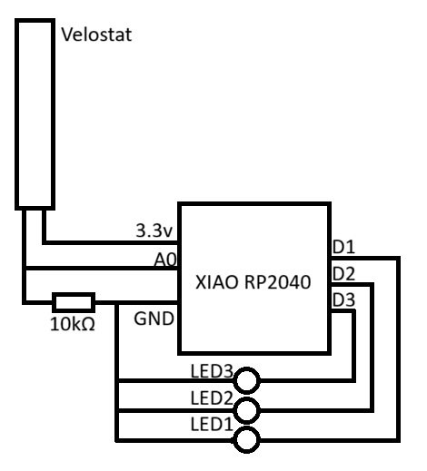
In theory this is how it is supposed to work, as the schematic bellow shows: * The Velostat works as a variable resistor when pressed/bent, which means that static can give a reading of 100kΩ, and when bent it has 10kΩ (as an example), this process must be intepreted by the microcontroller to do what we need. * A finger glove with the Velostat sandwiched is conected to the Xiao RP2040 Microcontroller through a 10kΩ resistor on the GND pin, to divide the voltage, as microcontrollers don't read resistance but voltage, this ensures that the reading is precise, and we can see a change in behaviour, this works with the formula Vout=Vin⋅(R2/R1+R2), the Velostat is a variable resistor, in this case R1, the 10kΩ resistor is R2, and the Vin is 3.3V * The other pin from the Velostat goest to the A0 analogue pin, which reads the previous voltage. * The microcontroller recieves the changes in voltage from the flexing of the finger glove. * This signal is then mapped into values and each value represents one of three cases, which turn each of the LEDs.
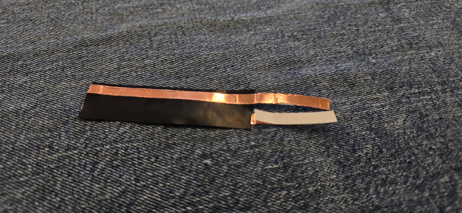
The first part is to build the finger glove respecting the principle of the Velostat, which goes sandwiched between two conductive strips, and it all goes sandwiched between cloth, in this case i will be using denim.

The software used here is Arduino IDE, which I believe is probably the best programming software for amateurs like myself. The first thing to do is adding the microcontroller, this is done on the File>Preferences menu. We have to add the following URL on the Additional boards manager URLs so the software can find them:
https://github.com/earlephilhower/arduino-pico/releases/download/global/package_rp2040_index.json


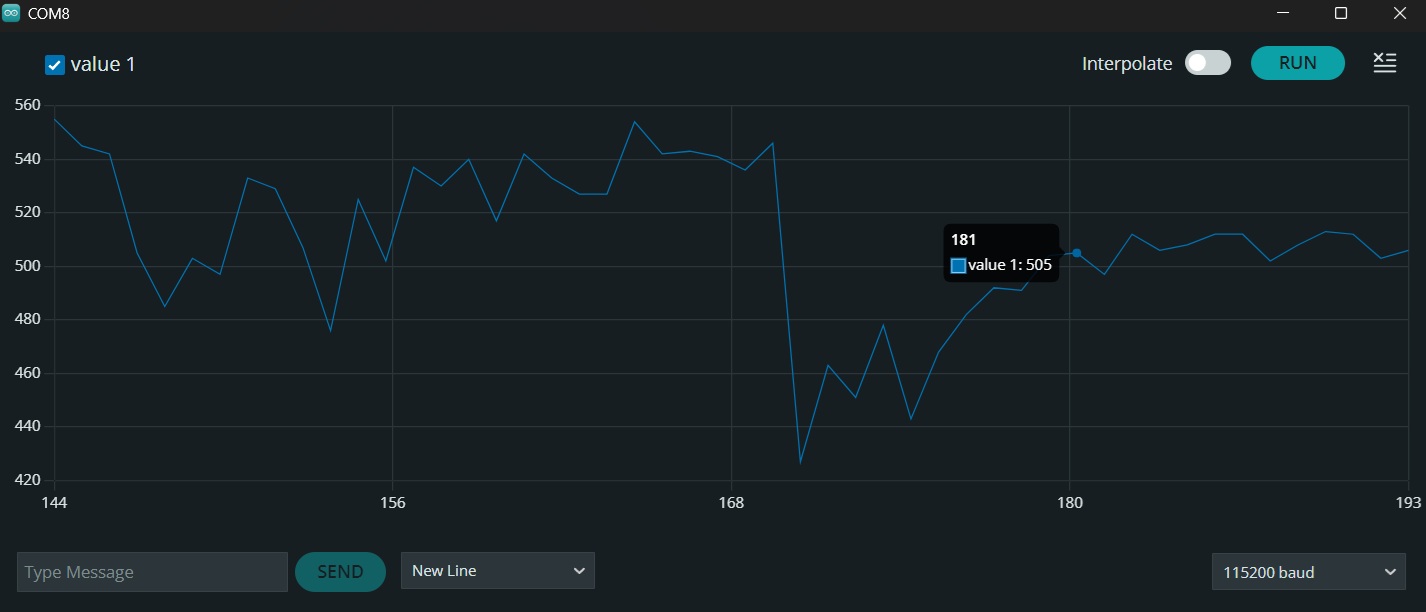
Then I wrote a small code for mapping the resistance values from the finger glove flexing, this will be our input for turning the LEDs afterwards. This is the code and the results from the serial plotting.
const int sensorPin = A0; // This selects which pin is recieving the data

void setup() {
  Serial.begin(115200);
  while (!Serial);
}

void loop() {
  int sensorValue = analogRead(sensorPin); // This reads the data from the defined pin

  // This sends the value it is reading
  Serial.println(sensorValue);

  delay(200); // This controls how fast the graphic scrolls.
}
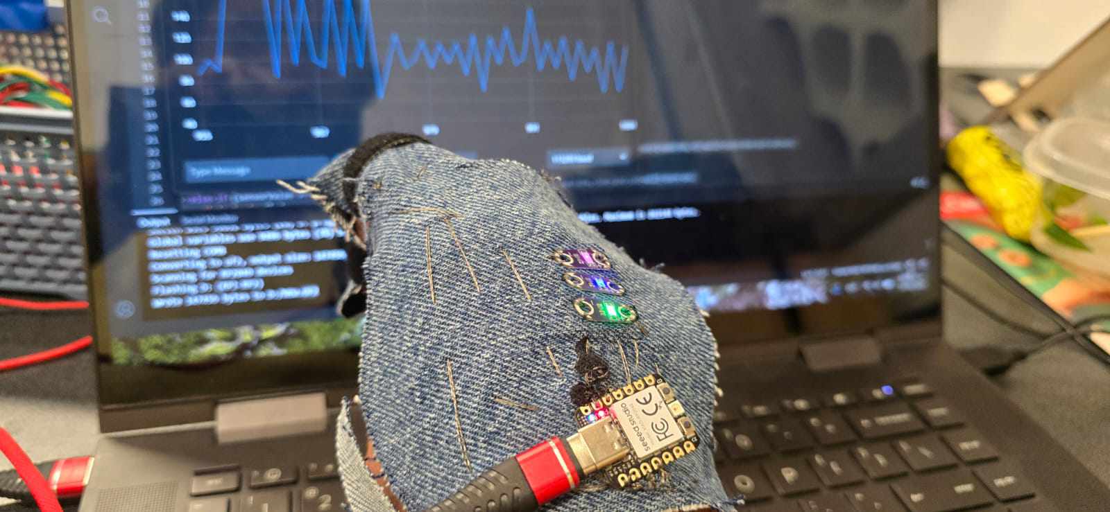
Having our minimum and maximum values for the flexing, which go from ~0 up to ~300, as it shows on the following graphic, now it's time to power the LEDs, which are plugged into the D1, D2, and D3 pins.
// Pins
const int sensorPin = A0;
const int led1 = D1;
const int led2 = D2;
const int led3 = D3;

void setup() {
  Serial.begin(115200);

  pinMode(led1, OUTPUT);
  pinMode(led2, OUTPUT);
  pinMode(led3, OUTPUT); // This defines the LED pins as output
}

void loop() {
  int sensorValue = analogRead(sensorPin);

  digitalWrite(led1, LOW);
  digitalWrite(led2, LOW);
  digitalWrite(led3, LOW);  // LOW means the pin remains powered off until something changes

  // Mapeo por rangos
  if (sensorValue >= 1 && sensorValue <= 99) {   // This means that, if the sensor reads a value between 1 and 99, it will turn the 1st LED on.
    digitalWrite(led1, HIGH);
  }
  else if (sensorValue >= 100 && sensorValue <= 199) { // For values between 100 and 199, the 2nd LED will turn on.
    digitalWrite(led2, HIGH);
  }
  else if (sensorValue >= 200 && sensorValue <= 300) { // For values between 200 and 300, the 3rd LED will turn on.
    digitalWrite(led3, HIGH);
  }

  Serial.println(sensorValue);  // This sends the values of the sensor to the serial plotter, so we can take a look at it.

  delay(200);
}
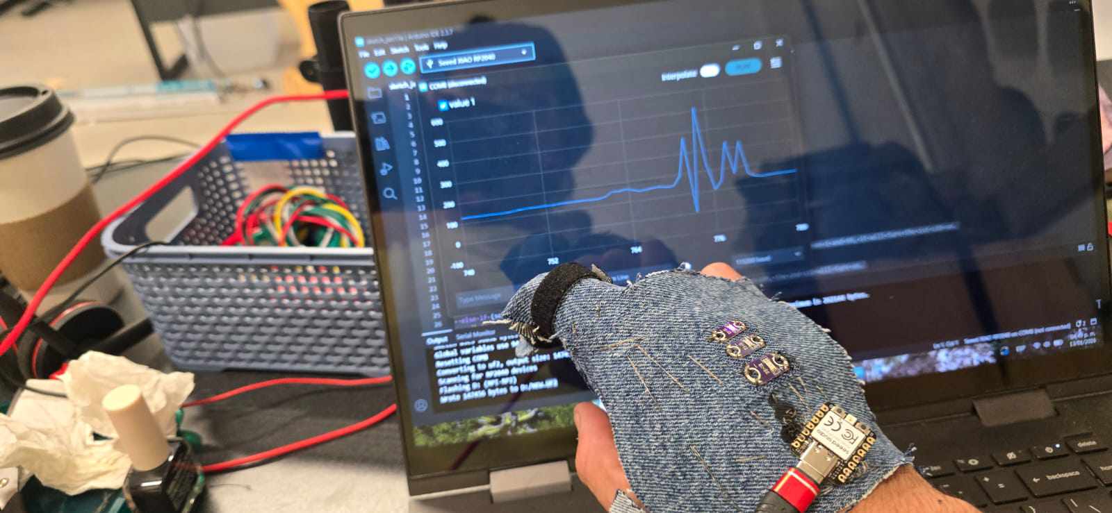
And now we just have to integrate it into a piece, I will also be using denim for that.
What went right?
The logic behind how to do this is very basic, and has very little space for failure, we get a reading from the "sensor" and it is interpreted by the microcontroller, and then turns the LED 1, 2 or 3. The code was very simple and didn't need a lot of tweaking.
What went wrong?
The velostat is a strange material and got a lot of noise from the readings, so the best solution i came up with is to insulate as much as I could with electrical tape and connect it with a 1kΩ resistor.
The frayed ends of the conductive thread are very unpredictable, and very easy to short the circuit, my instructor recommended to use some nail polish to insulate them before something bad happened.
The conductive thread doesn't behave at all like regular thread, it untangles, frayes and shorts everything, I would recommend to use an alternative like thin copper wire, not my best work.
Adjustments
It is possible to use two different pieces of Velostat each with their own conductive tape, for better readings.
Conclusion
This week's assignment allowed me to understand electronics not as an add-on, but a material inside of the textile ecosystem.
Results
I'm pretty happy with the result, there is a sweet spot where it blinks too much between the two LEDs, but i don't think its a real issue.
Digital Sensor
For the digital sensor i wanted to experiment with off-the-shelf Heart Rate sensors that can be integrated seamlessly on garments like gloves, jewelry and even belts, for example.
Inspiration and Research
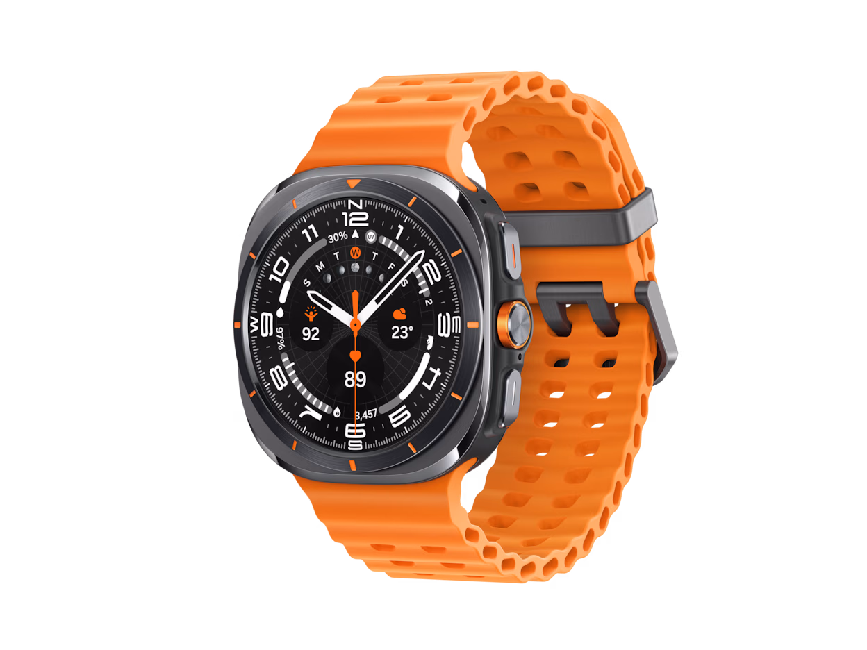
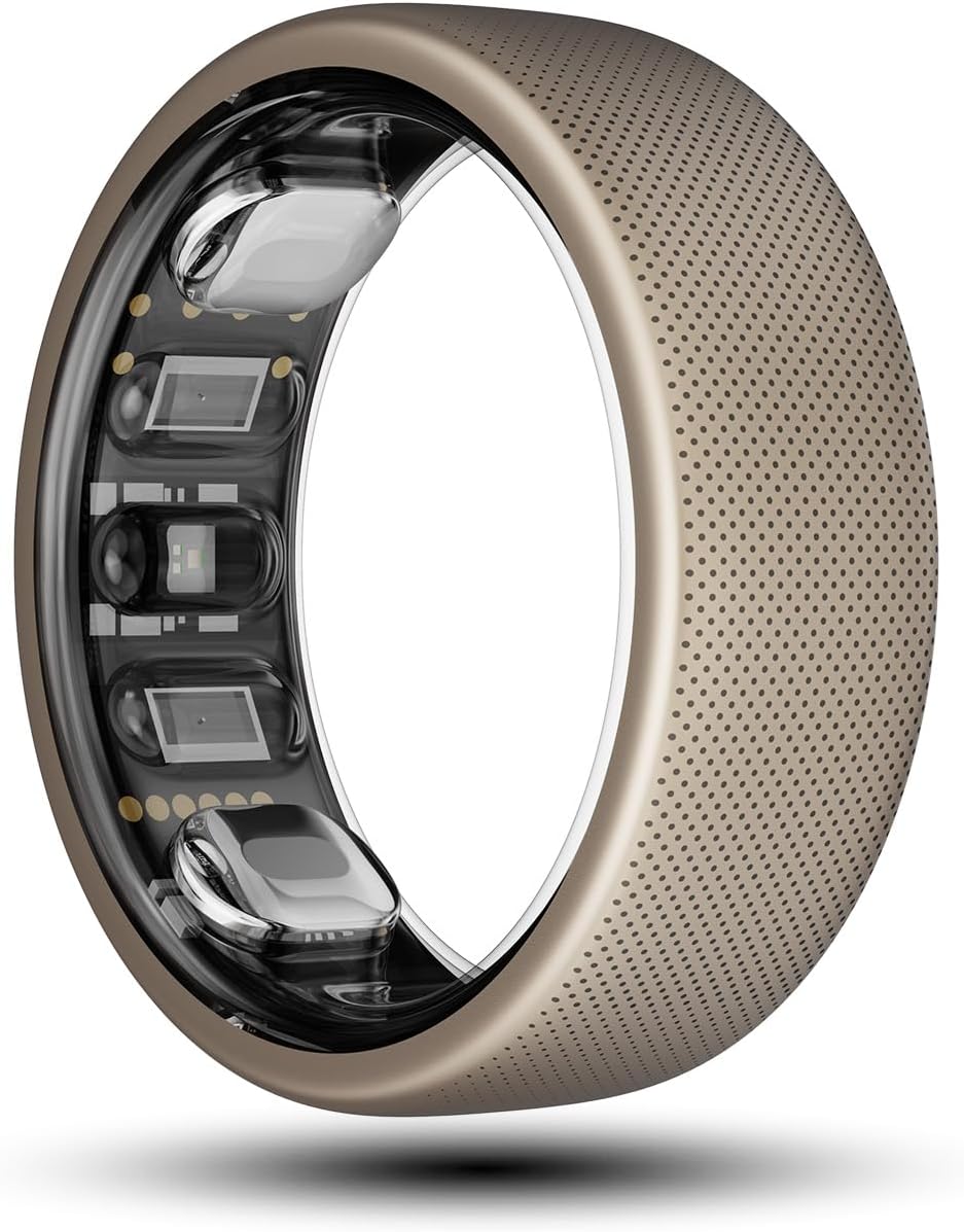
I have always been intrigued about how do Heart Rate sensors work, as they have been integrated in everyday life through smartwatches, smartphones and non-invasive medical devices. Fortunately this devices have become very accesible, for example this cheap Pulse Sensor Module (SE050) costs around $5 USD and it's easy to find almost everywhere. My favourite garments with heart monitoring are: * The Garmin HRM-600 - Dedicated heart rate monitor that sends data to your devices, to track heart rate and Variability of such heart rate. * Smartwatches - In general the Applewatch, the Samsung Gear, Xiaomi. * SmartRings - I think this is probably the most interesting design i have seen on heart rate monitoring, and even step tracking, phone notifications, etc.
Process
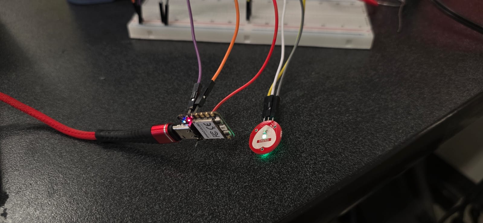
The working principle is "simple", this sensors have a green LED that lights up the veins, and it also has a optic sensor, somewhat like a tiny camera without a lens, which picks up differences on each "photo" it takes, that's how it detects the movement of the blood inside of the veins. This variations are then sent to the microprocessor, the mighty XIAO RP2040, which can interpret the data and act accordingly. I would like to add two LEDs that light up alternately depending on the heart rate, and integrate everything on a glove.
The first part is to find out what kind of signal comes out of the sensor, so I sketched a simple code and circuit, and tested the measures, to calibrate the proper values that i want to use for the piece with the LEDs. * Ground and 3.3V were connected to the - and + terminals, respectively, on the sensor. * The S (for signal) from the sensor was connected to the top left pin on the XIAO, which is the input pin 0. * The code was written as it follows:
const int pulsePin = A0; // This is the Signal pin
int threshold = 515; // When the readings go above this number, it "counts" as a heartbeat

void setup() {
  Serial.begin(9600);
}

void loop() {
  int signal = analogRead(pulsePin);

  Serial.print(signal);  // This prints the value of the incoming signal.
  Serial.print(",");
  Serial.println(threshold);  // This prints the minimum value to "count" a heartbeat

  delay(50);
}
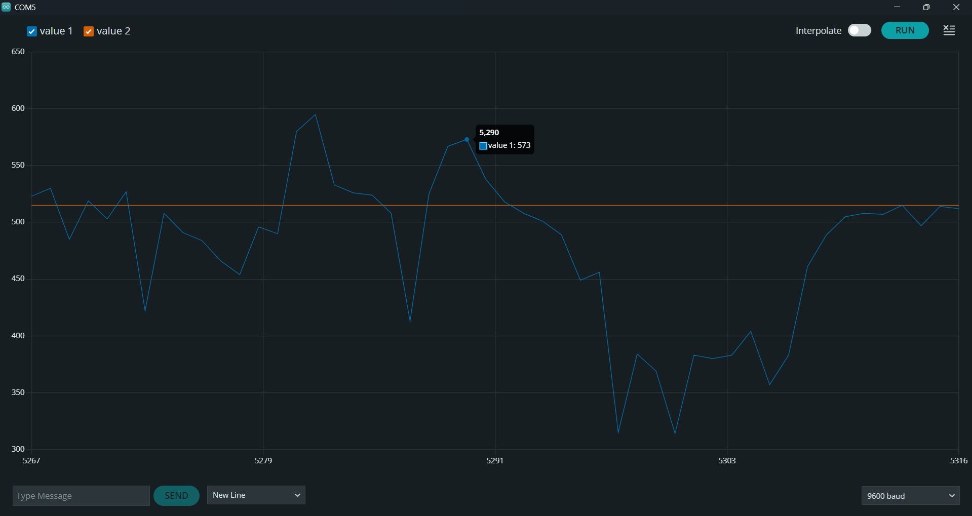
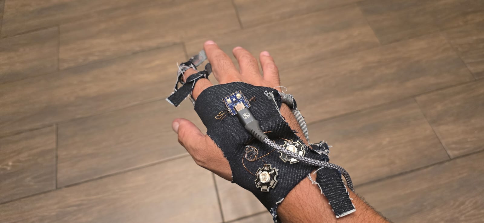
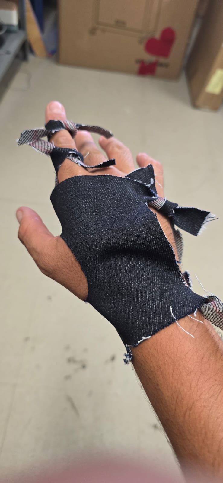
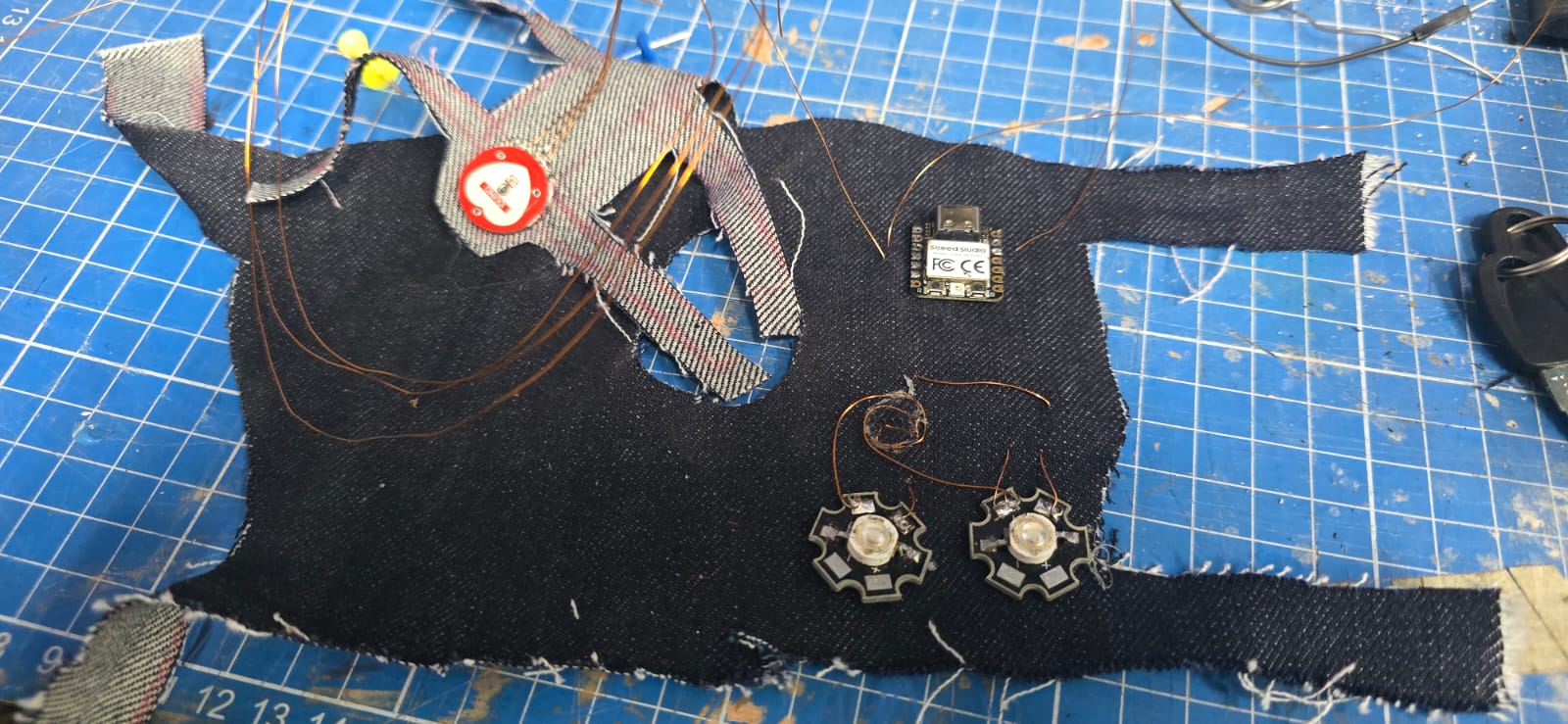
Having tested and calibrated the heart rate monitor, now let's do something more interesting. I started by tracing my hand and cutting a pattern on the same denim i used on the previous exercise. I tied the ends to ensure the fit, and marked the places for the LEDs, the XIAO, and the HR sensor. To all the terminals needed, thin gauge enameled copper wire was soldered and then stitched using the "glove" as base to connect them to the XIAO. I also used hot glue to paste the components to the glove.
The next part was to design the code to make the LEDs reactive to the HR. I want the two LEDs to alternate with the heart rythm, and also to calculate the Beats per minute. So the code goes as it follows:
const int pulsePin = A0;
const int led1 = 2;
const int led2 = 3;

int threshold = 550;

bool beatDetected = false;
unsigned long lastBeatTime = 0;
int BPM = 0;

bool toggleLED = false;

// -------- FUNCION DE LATIDO --------
void heartbeatFade(int ledPin) {

  // Primer golpe (fuerte)
  for (int i = 0; i < 255; i += 5) {
    analogWrite(ledPin, i);
    delay(2);
  }

  for (int i = 255; i > 120; i -= 5) {
    analogWrite(ledPin, i);
    delay(2);
  }

  // Segundo golpe (más suave)
  for (int i = 120; i < 200; i += 5) {
    analogWrite(ledPin, i);
    delay(2);
  }


  for (int i = 200; i >= 0; i -= 3) {
    analogWrite(ledPin, i);
    delay(3);
  }

  analogWrite(ledPin, 0);
}

void setup() {
  Serial.begin(115200);

  pinMode(led1, OUTPUT);
  pinMode(led2, OUTPUT);
}

void loop() {
  int signal = analogRead(pulsePin);


  Serial.println(signal);

  if (signal > threshold && !beatDetected) {
    beatDetected = true;

    unsigned long currentTime = millis();
    unsigned long delta = currentTime - lastBeatTime;

    if (delta > 300) {    //This part filters some of the noise from the signal
      BPM = 60000 / delta;
      lastBeatTime = currentTime;

      Serial.print("BPM: ");
      Serial.println(BPM);

      // Alternating LEDs
      toggleLED = !toggleLED;

      if (toggleLED) {
        heartbeatFade(led1);
      } else {
        heartbeatFade(led2);
      }
    }
  }

  if (signal < threshold) {
    beatDetected = false;
  }

  delay(5);
}
Having the code updated we have the following results.