12. Skin Electronics
Research
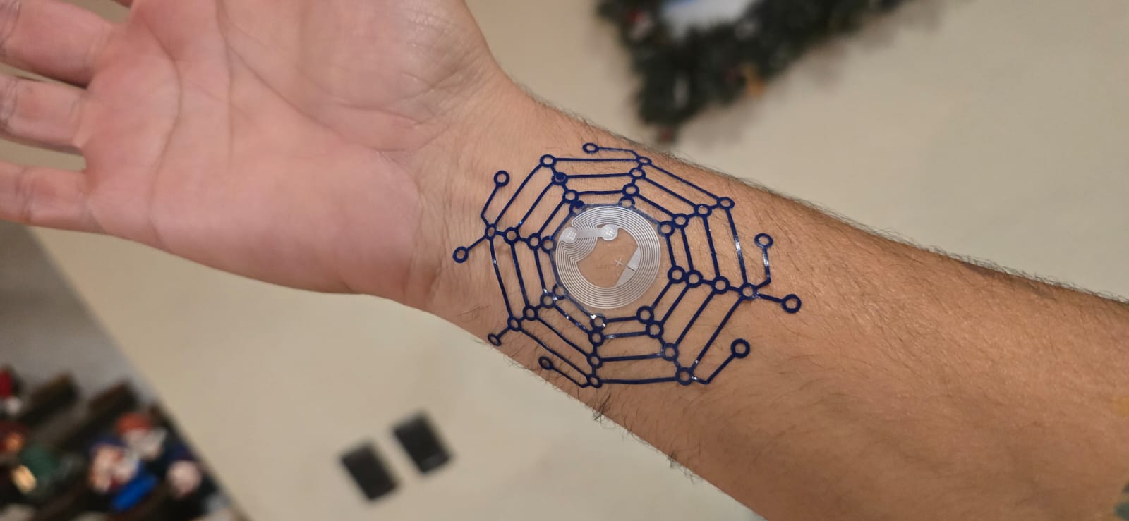 This week's exploration is about Skin Electronics, an interesting approach to electronics in which we abandon the rigidity of circuits and integrate them in the body in an almost imperceptible manner.
What if skin could also connect, what if electonics could stop being cold and structured, to become warm, soft, intimate; a circuit that beats with movement, a bridge between body and machine.
Skin electronics is the design of electronic components that can bend, stretch, and adapt to organic surfaces, like human skin. This includes sensors, actuators, anthenas and flexible printed circuits. For this week I will design two separate projects, one based on the NFC technology and the other one will be a functional heart rate monitor embedded/pasted on the skin, somewhat like a technologic tattoo.
Inspiration
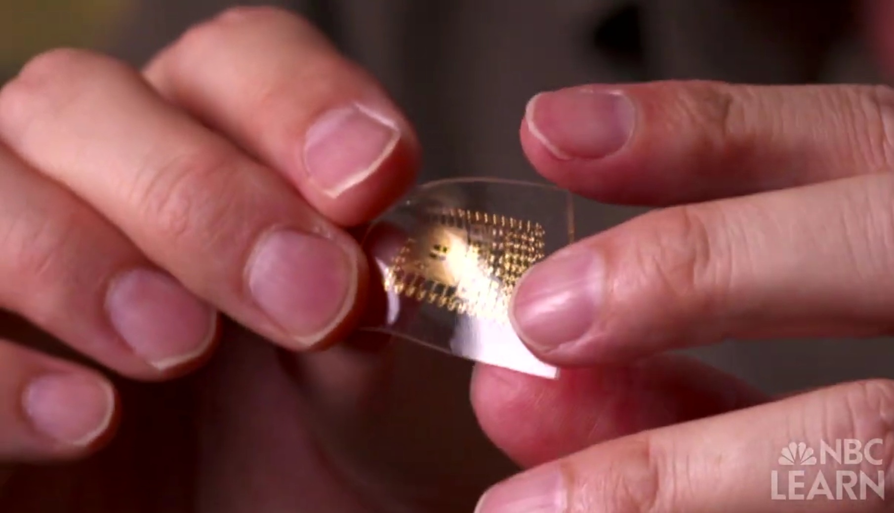
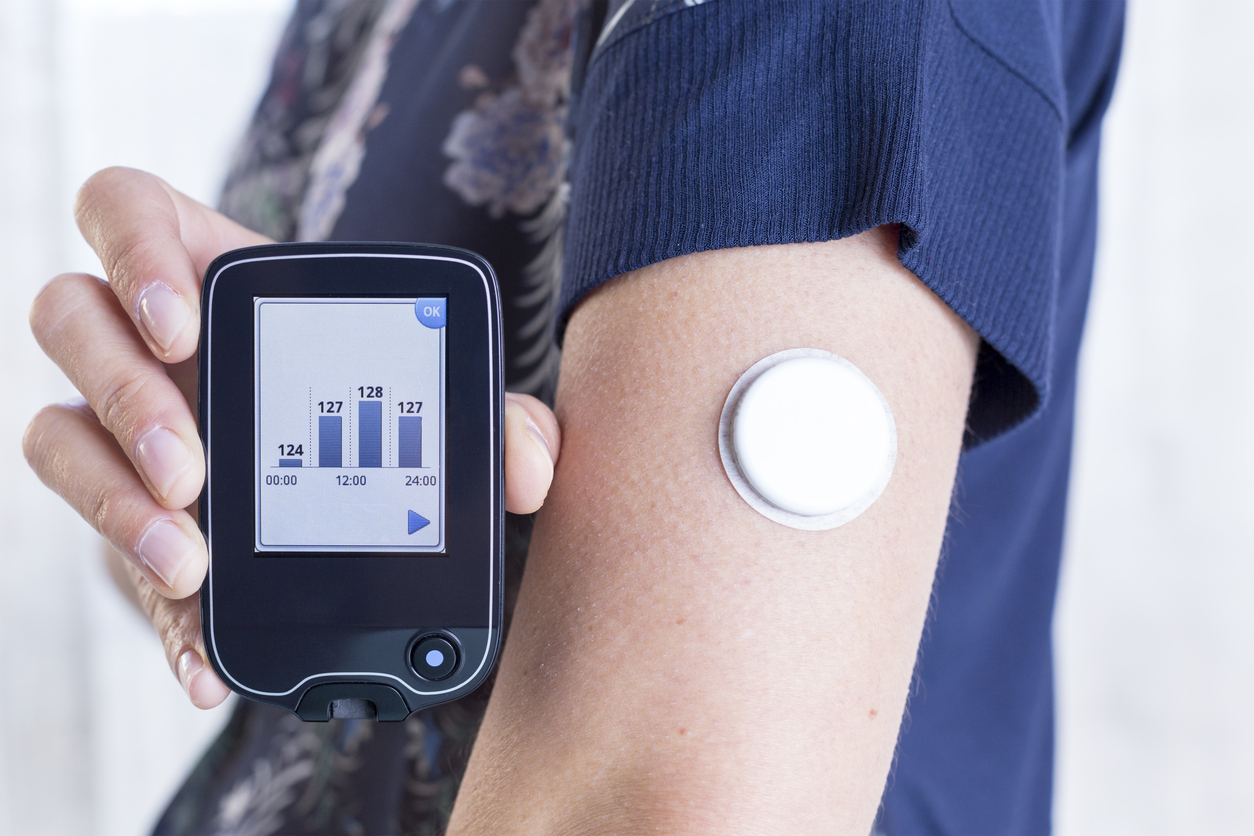
The first time I read/heard about E-tattoos was from this video from 2013 which mentions tiny sensors that could monitor different health indicators like stress levels or even heart rate, they are disposable and efficient, stick easily to the skin and confortable. And the technology has evolved tremendously in such short time, for example the glucose measurement devices for people who suffer diabetes are minimally invasive, they even connect to your devices to inform the patient of the current status. Working with different techonlogies i can only wonder about the next generation of health monitoring, not a device you wear, but something so discreet, you forget it is even there.
Part I: NFC Tags
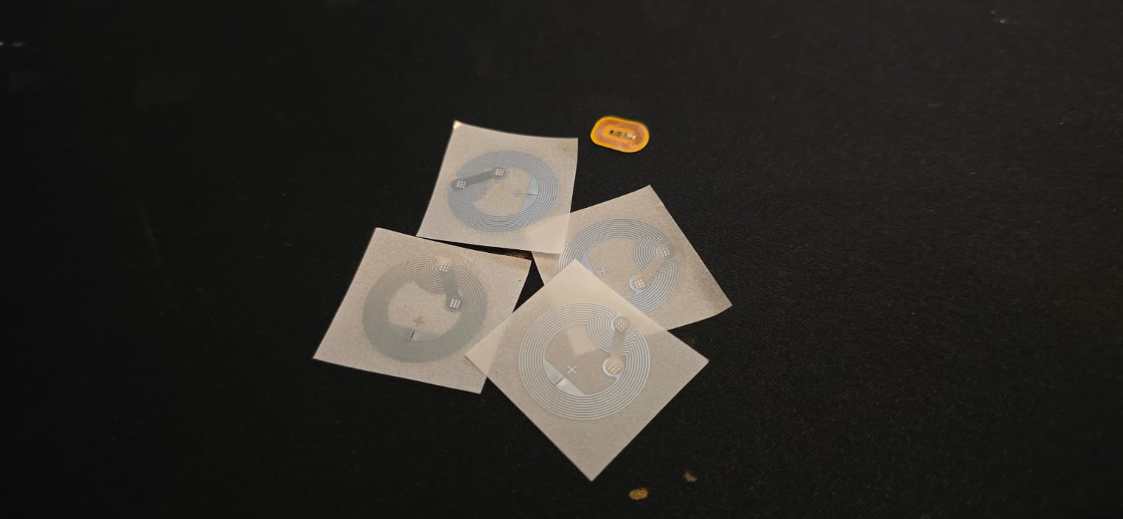
What is NFC? It means Near Field Communication which allows devices to exchange data when they are close together, through a wireless short-range radio field of 13.56 MHz. The NFC Tags are considered passive devices, because they don't have batteries, as they are powered by the reading device's field.
The first part is to design a cool Cyberpunk Tattoo which will surround the NFC tag, I was thinking of either octopi or spider themed, with a tech-aesthetic look. At the end I chose a spider's web with nodes and holes resresembling a circuit. I designed with the vector tools from Affinity Studio, and transformed it into a .png with the combine tool, and Export as PNG.
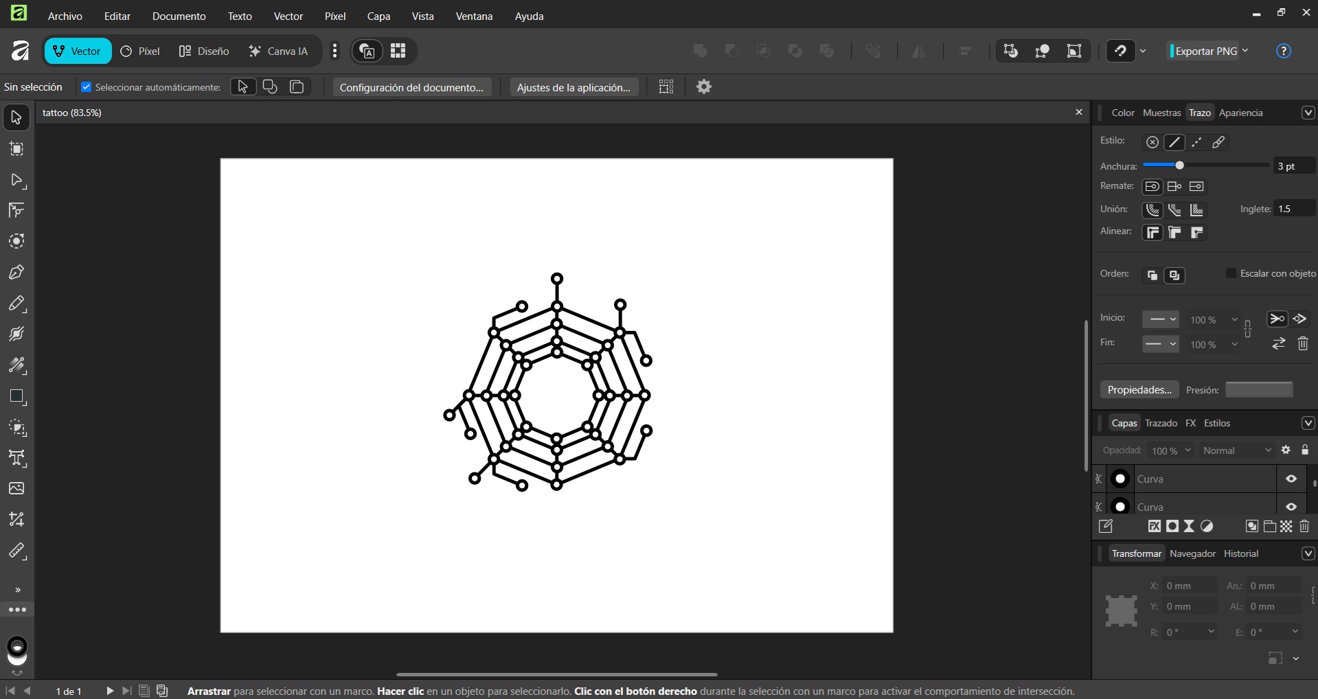
I'm using the Silhouette Portrait 3 vinyl cutter for the tattoo part, so I'm using the Silhouette Studio Software for controlling the machine.
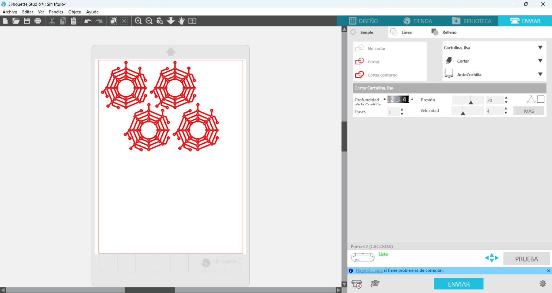
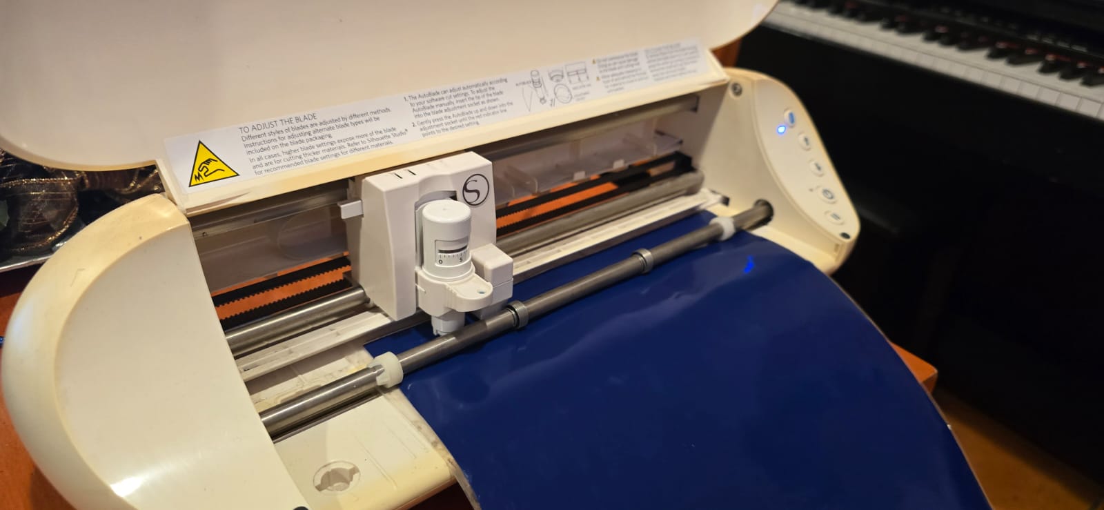
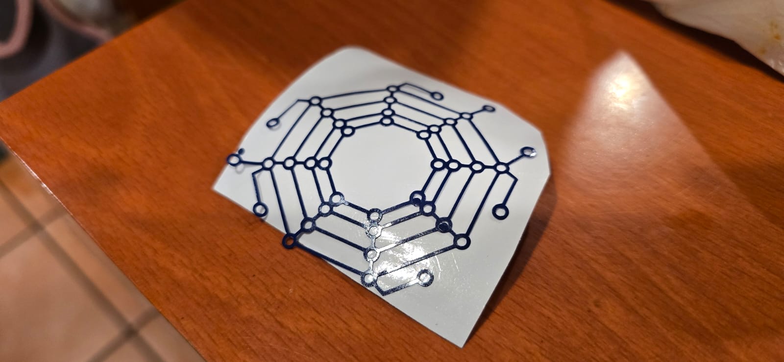
I'm using blue vinyl for this tattoo, and the NFC tag will be in the middle of the composition.
The next part is to program the NFC Tag using an app called NFC Tools that allows us to read and write data on the tags, in this case i'm writing my personal url for contact. The app is very easy to use, and on the write tab we can do all sorts of tasks, like connect to a wifi network, link to a video online, go to a map in google maps or even a link to a bitcoin address. In this case i'm connecting it with the previous URL so it opens up my contact info when read.
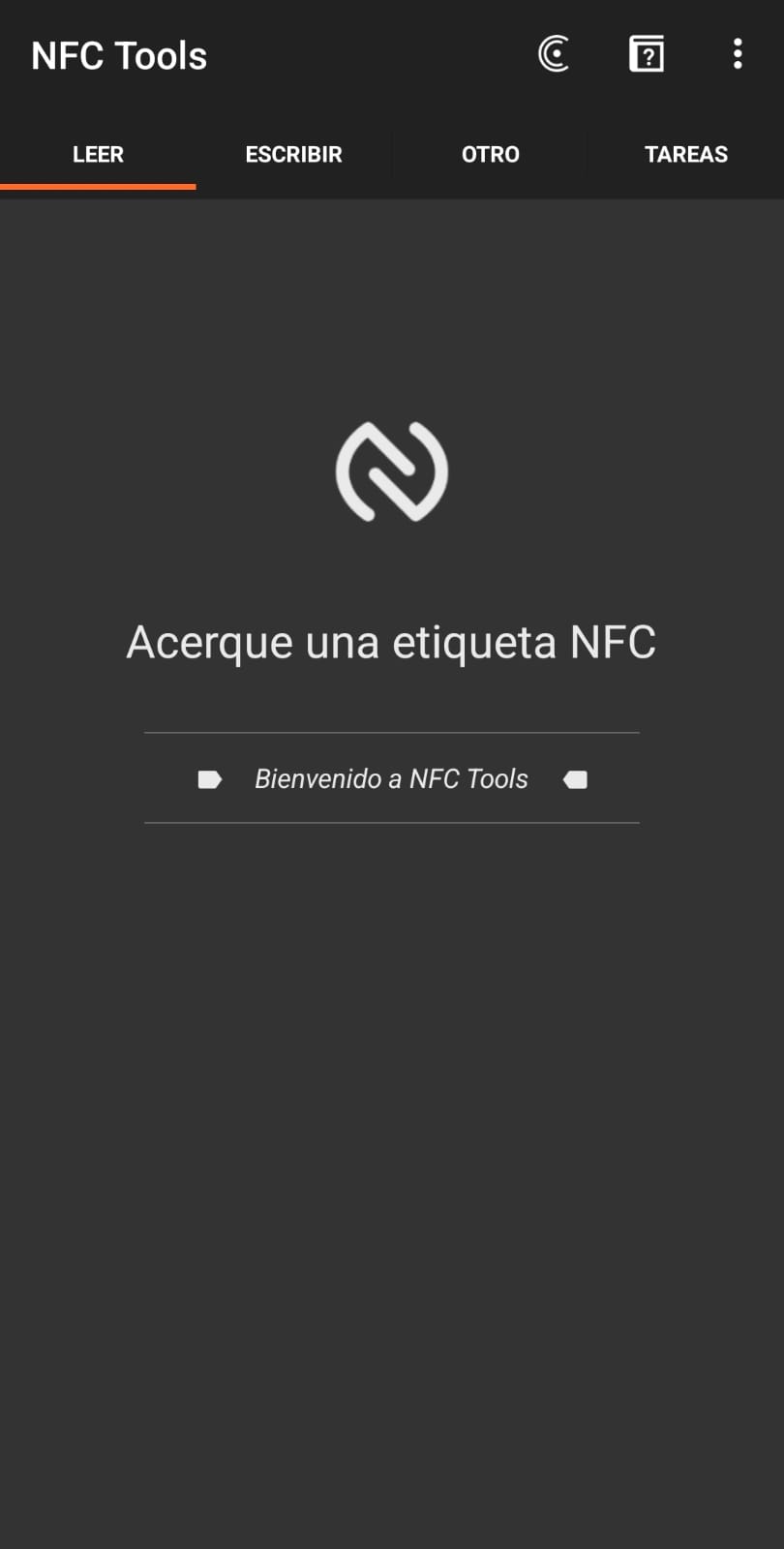
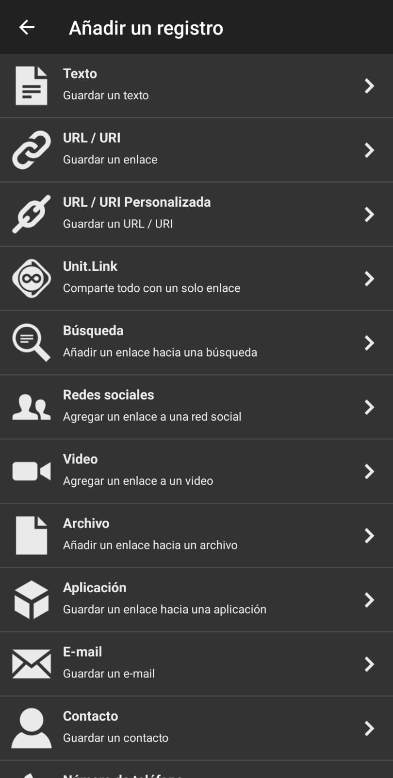
Finally is time to merge both parts in an interactive tattoo.
Part II: Electronic Circuit
For this part i will be using a tiny chip, the Xiao RP2040, which is compatible with a wide variety of sensors. What I want this device to do is the next:
- It must be tiny and confortable
- It should be somewhat sticky for it to remain attached to the skin
- It must have a heart rate monitor, which uses a green LED and a small optic sensor to determine the bloodflow in a vein.
- It must have some kind of indicator, like a LED, or a buzzer
- I'm planning on using copper tape for the circuitry, so it is flexible and adaptable to the skin
- It must use batteries, so a small 3V button battery will be perfect for this project.
Concept & Design
Having this restrictions in mind, and having the inspiration from the products above, I started designing the most optimal way to allocate the components.
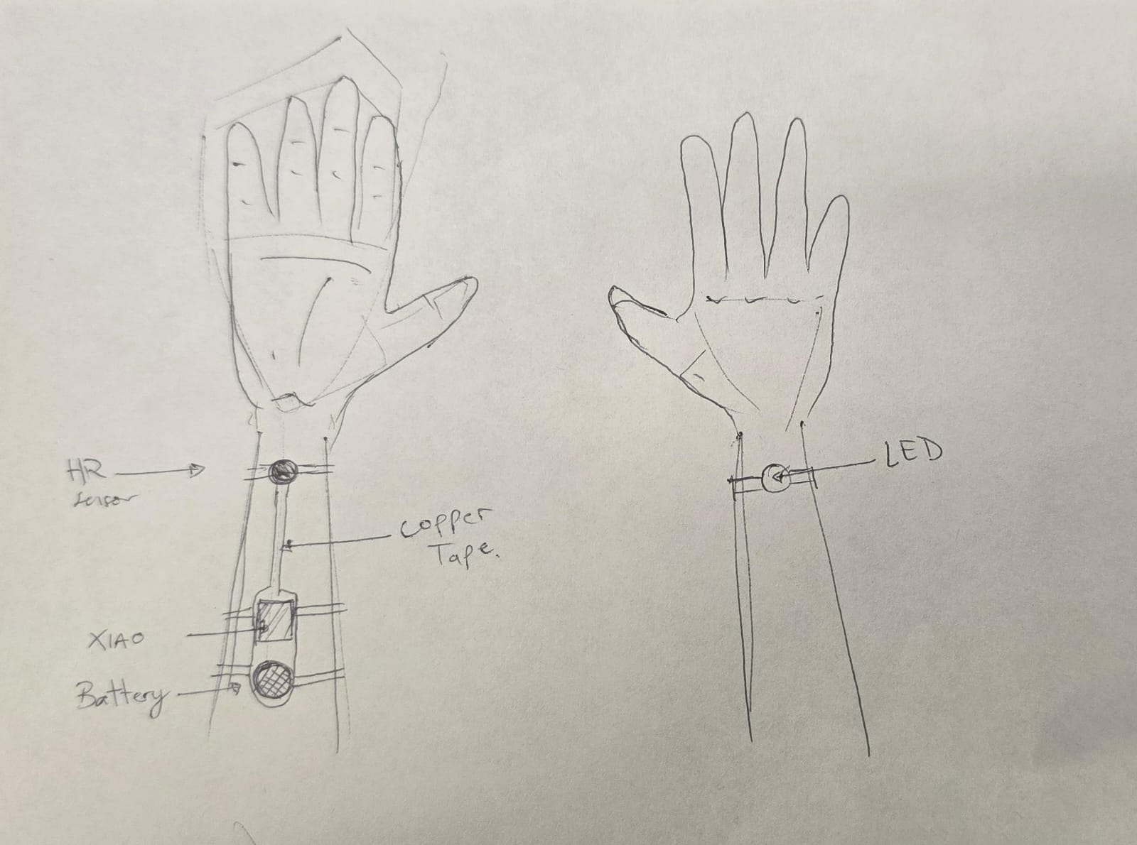
Then, the appropiate circuit schematic for connections goes as it follows:
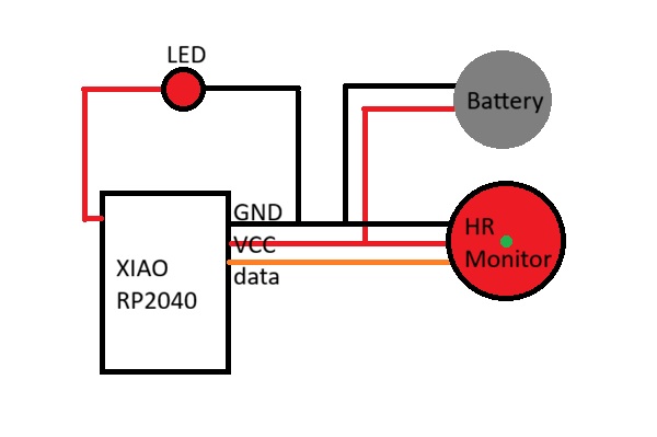
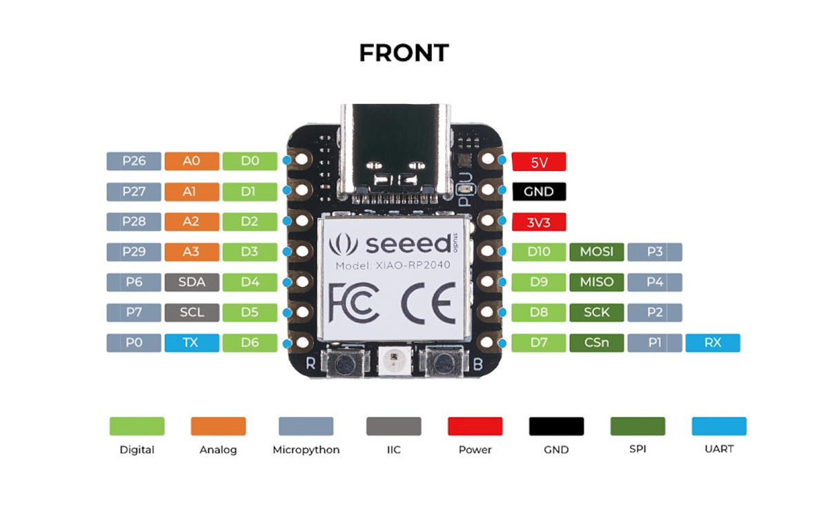
The data is transfered through the D10 Pin from the heart rate sensor, then processed and a signal is sent to the LED for blinking at the same pace through the D0 Pin, In theory.
With the help of the previous assignment:E-textiles I was able to evolve the wearable for this assignment, making it smaller, "embedded" on the skin and more aesthetically pleasing. The first prototype of the code looks like this:
const int pulsePin = 10;
const int led = 0;


int threshold = 550;

bool beatDetected = false;
unsigned long lastBeatTime = 0;
int BPM = 0;

bool toggleLED = false;

// -------- FUNCION DE LATIDO --------
void heartbeatFade(int ledPin) {

  // Primer golpe (fuerte)
  for (int i = 0; i < 255; i += 5) {
    analogWrite(ledPin, i);
    delay(2);
  }

  for (int i = 255; i > 120; i -= 5) {
    analogWrite(ledPin, i);
    delay(2);
  }

  // Segundo golpe (más suave)
  for (int i = 120; i < 200; i += 5) {
    analogWrite(ledPin, i);
    delay(2);
  }


  for (int i = 200; i >= 0; i -= 3) {
    analogWrite(ledPin, i);
    delay(3);
  }

  analogWrite(ledPin, 0);
}

void setup() {
  Serial.begin(115200);

  pinMode(led1, OUTPUT);
  pinMode(led2, OUTPUT);
}

void loop() {
  int signal = analogRead(pulsePin);


  Serial.println(signal);
This code was based on the previous one, for the E-textiles assignment. Connecting everything where it belongs over the protoboard, the result was the next:
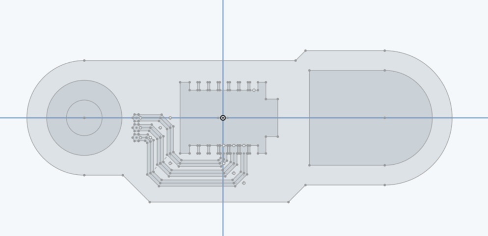
The next part is to design the propper circuitry for fabrication, so I used the online software OnShape where I started drawing the reference parts for the final product: The XIAO RP2040 footprint and pins dimensions and allocations, the battery and HR sensor, then a few lines that would be the circuit paths.
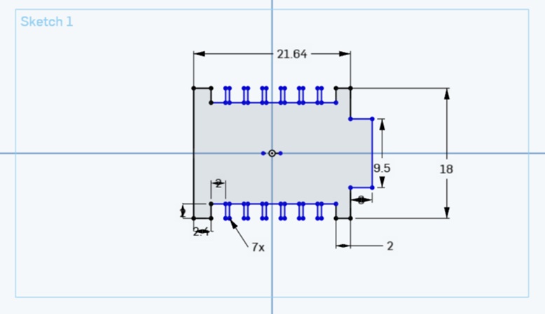
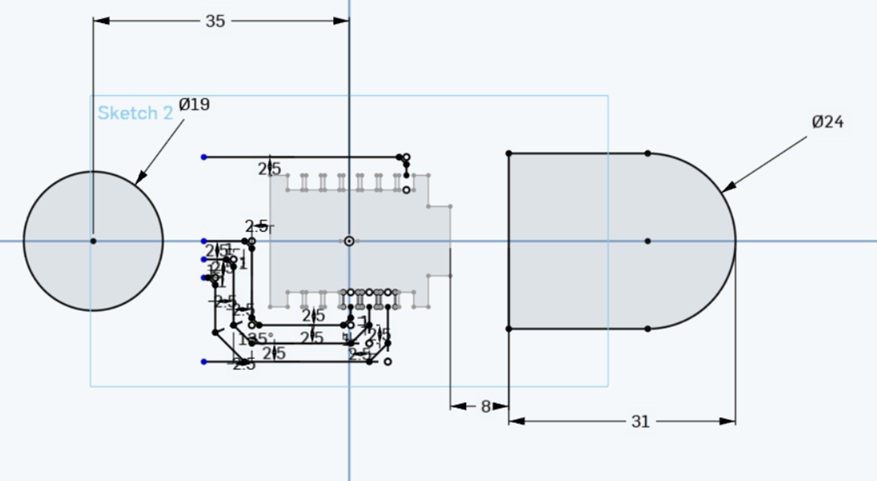
Afterwards, using the Variable table on the OnShape menu, it was possible to parametrize the thickness of the paths in case it was necessary to reduce or grow them, and with the offset tool we had our final paths for every component.
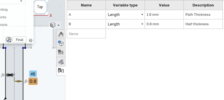
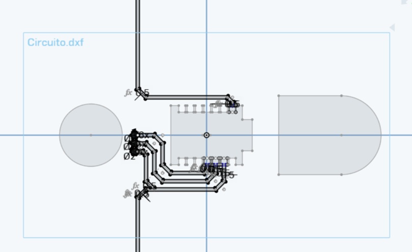
The next step is to draw the contour of the piece, that will be stuck to the skin, and where the circuit will be soldered. Using offsets and lines at a distance from the circuit paths, the outside was done. All that was left was to export both the paths and the vinyl part, by using the right-click over the sketch, and exporting to .dxf
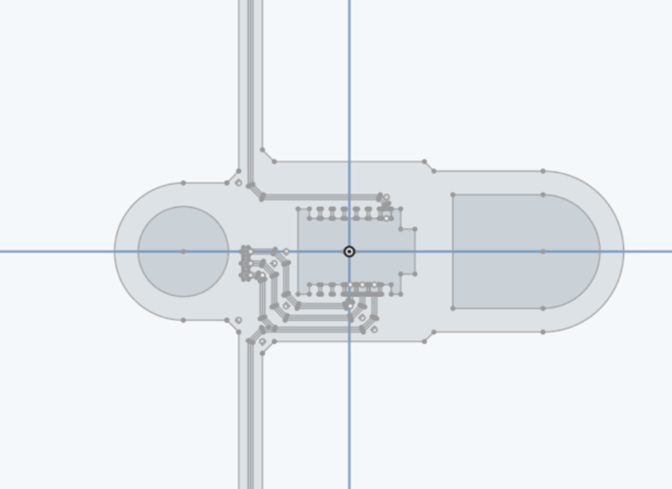
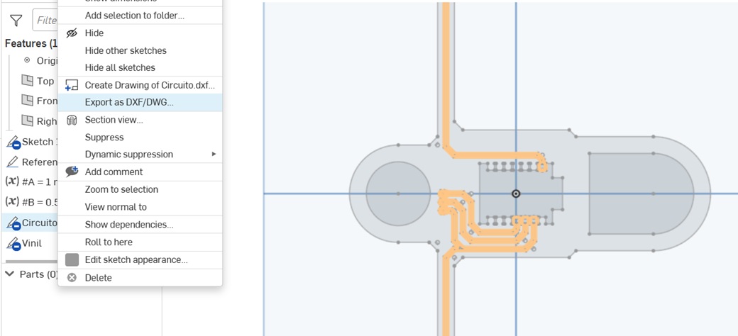
In theory it was very easy to just cut the circuit from Copper tape, and the vinyl base with the Silhouette Portrait 3, a compact and easy to use vinyl cutter. But it failed too many times because the adherence to the mat was not great, the force was either too much or too little, The tape stuck to itself and was imposible to unstick, or while peeling the exterior of the paths, everything just broke.
- Bad news: it took me around 9 misshaps to understand what was going on over the course of 4 hours.
- Good news: I could finally understand what i was doing wrong and was able to correct it, and fabricate a new batch in just 5 minutes.
The first workflow worked like this, and if anything failed, the process would start again:
- The file was sent to the machine to cut the copper tape
- If it didn't fail, it was time to peel the extra bits
- If that didn't fail, now it was the time to cut the vinyl over which the circuit will be stuck
- Vinyl cutting rarely fails, but if that didn't fail, now we had to paste the delicate circuit over the vinyl
- Afterwards it was time to solder the components, and if it didn't fail, I guess voilá (¿?)
- Of course i didn't got that far, so it was time to rethink the process.
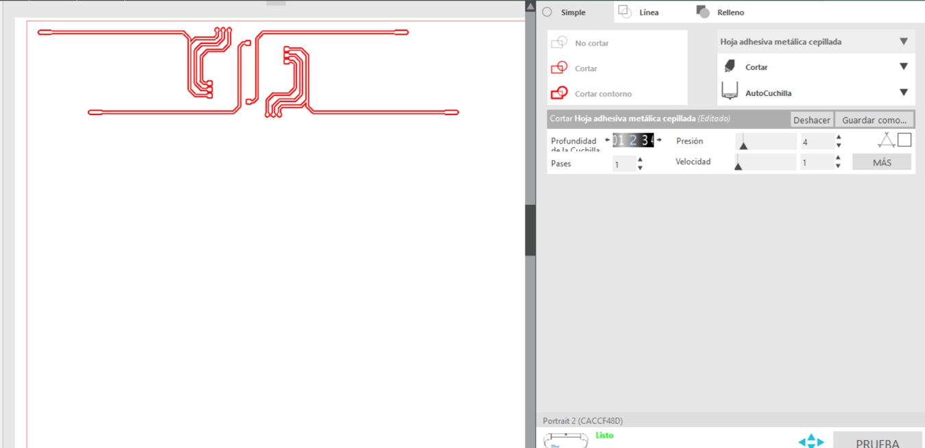
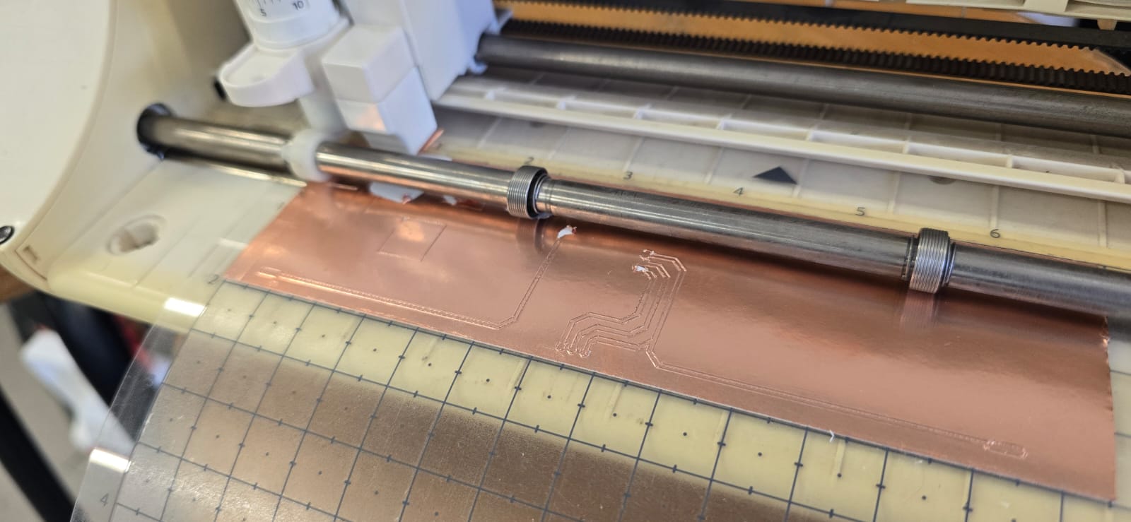
The best approach was the following:
- Instead of cutting each part separately, both were cut on the same file, at different times.
- First we imported both parts on the Silhouette studio software, and configured the outside part only
- The outside part is cut on black vinyl, then the copper tape is added where needed
- The circuit is then cut at very low speed, pressure and depth, so it only gets scored
- Then another pass is done with both vectors, at medium depth, but still low speed and pressure
- Afterwards the peeling process, while tedious, was easy enough that non of the paths got broken
- Finally a test went right! (Or did it?)
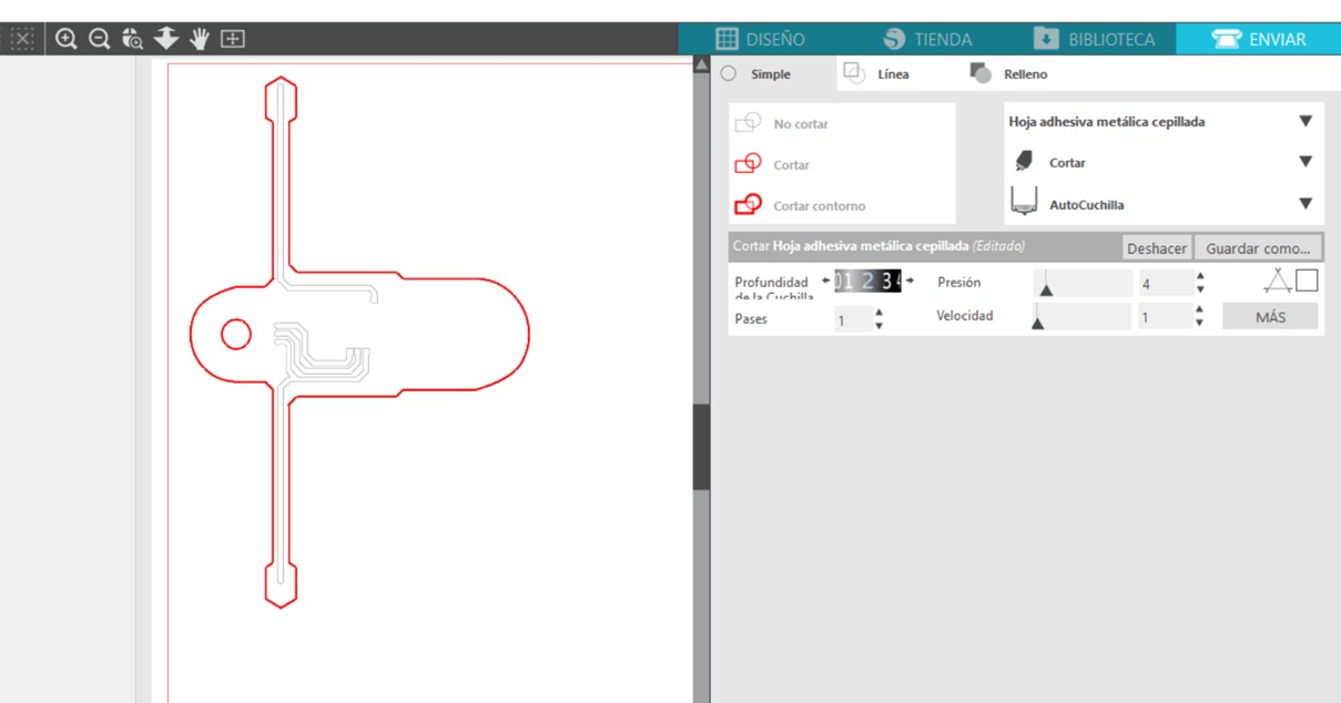
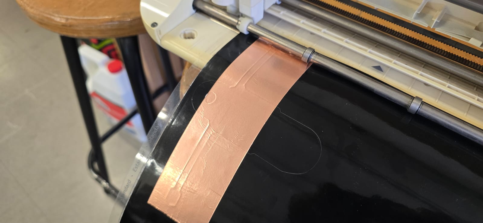
Then we just had to solder the components and we are done! (or are we?) The part that held the LED was designed as a bracelet around the wrist, but the movements i did to both solder and unstick from the mat were too rough, so the pieces got broken and unsoldered. It was time to go back to the drawing board.
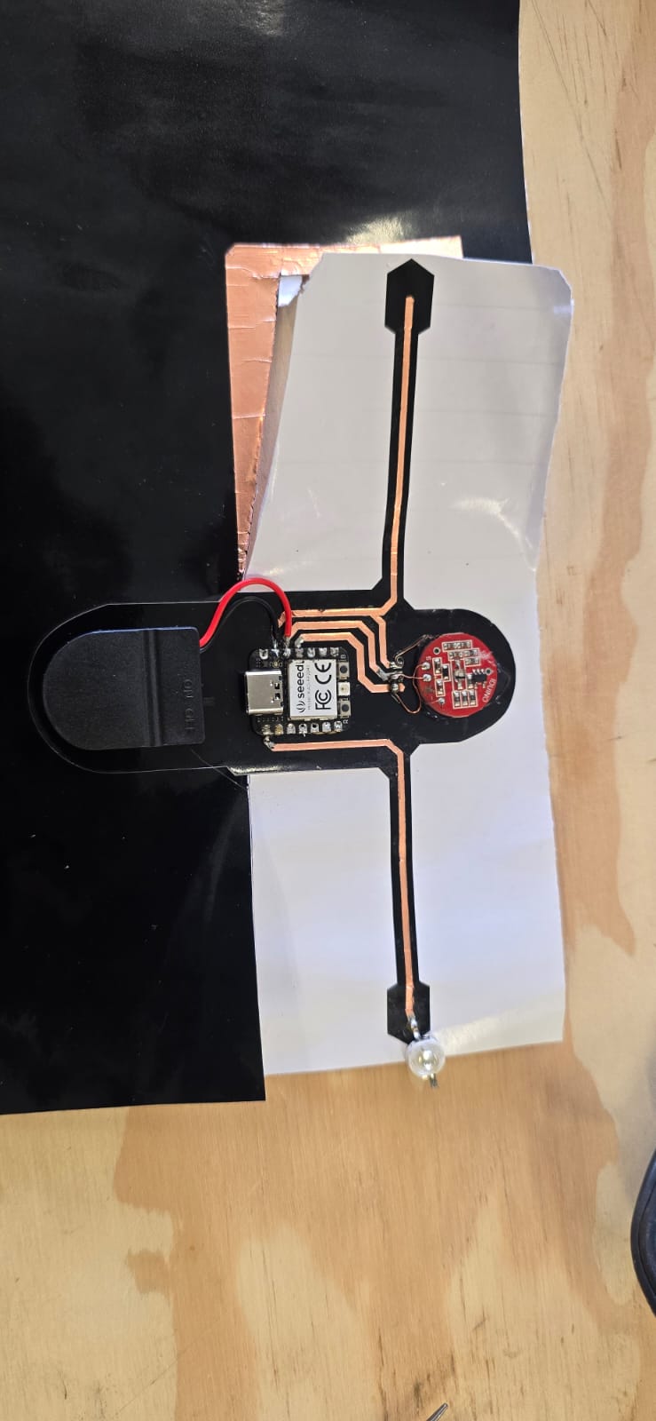
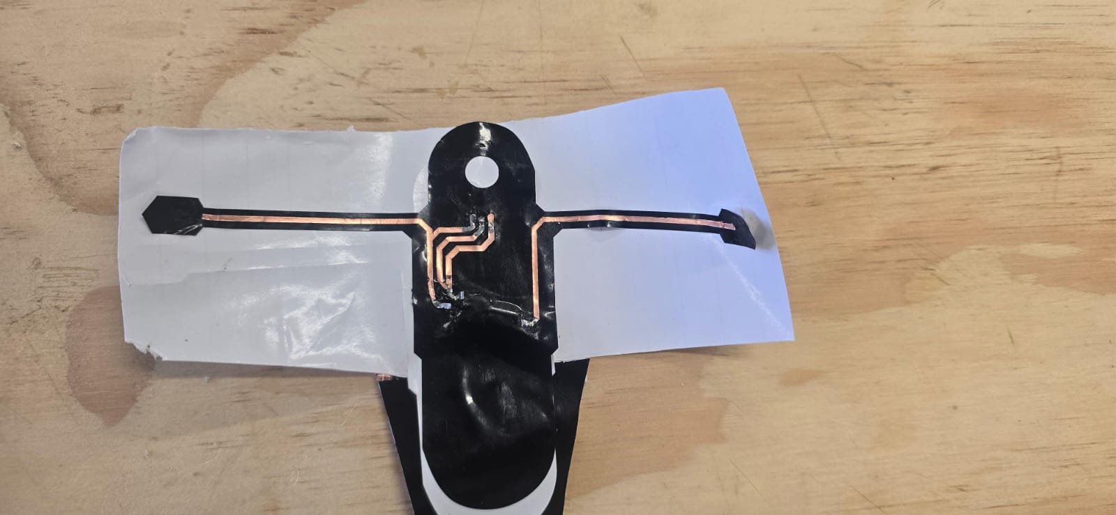
I figured that we could use the already-available neopixel on the Xiao RP2040 (3) for showing the heart rate in a beautiful way, so the external LED was removed from the circuit (on the 3rd iteration), so the code had to change a little bit, instead of using the LED pin (I think it was the D0), we use the NEOPIXEL library for controling both brightness and colour.
const int pulsePin = D10;
const int ledPin   = D0;

int signal = 0;


int threshold = 600;

bool beatDetected = false;

unsigned long lastBeat = 0;
const int debounce = 300;

void setup() {

  pinMode(ledPin, OUTPUT);

  Serial.begin(115200);

  analogReadResolution(12);    // 0 - 4095

}

void loop() {

  signal = analogRead(pulsePin);

  // Mostrar señal
  Serial.println(signal);

  // Detectar pico
  if(signal > threshold && !beatDetected &&
     millis() - lastBeat > debounce)
  {
      beatDetected = true;
      lastBeat = millis();

      heartbeatLED();
  }

  if(signal < threshold - 30)
  {
      beatDetected = false;
  }

  delay(5);

}

void heartbeatLED()
{

    // Fade In
    for(int i=0;i<255;i+=5)
    {
        analogWrite(ledPin,i);
        delay(4);
    }

    // Fade Out
    for(int i=255;i>0;i-=5)
    {
        analogWrite(ledPin,i);
        delay(6);
    }

    analogWrite(ledPin,0);

}
The circuit had to be redesigned, and the outside vinyl figure was also corrected to embrace these changes. There was a hole added for the Heart rate monitor LED. And both vectors, following the same process for exporting, were cut with the vinyl cutter.
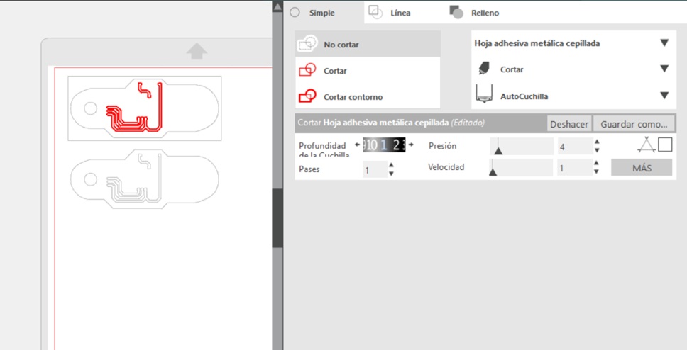
The process for cutting was the same as explained above, first the vinyl was cut, then the copper tape was placed, scored, and both vectors completely cut afterwards, and the components soldered with precaution so the vinyl didn't melt.
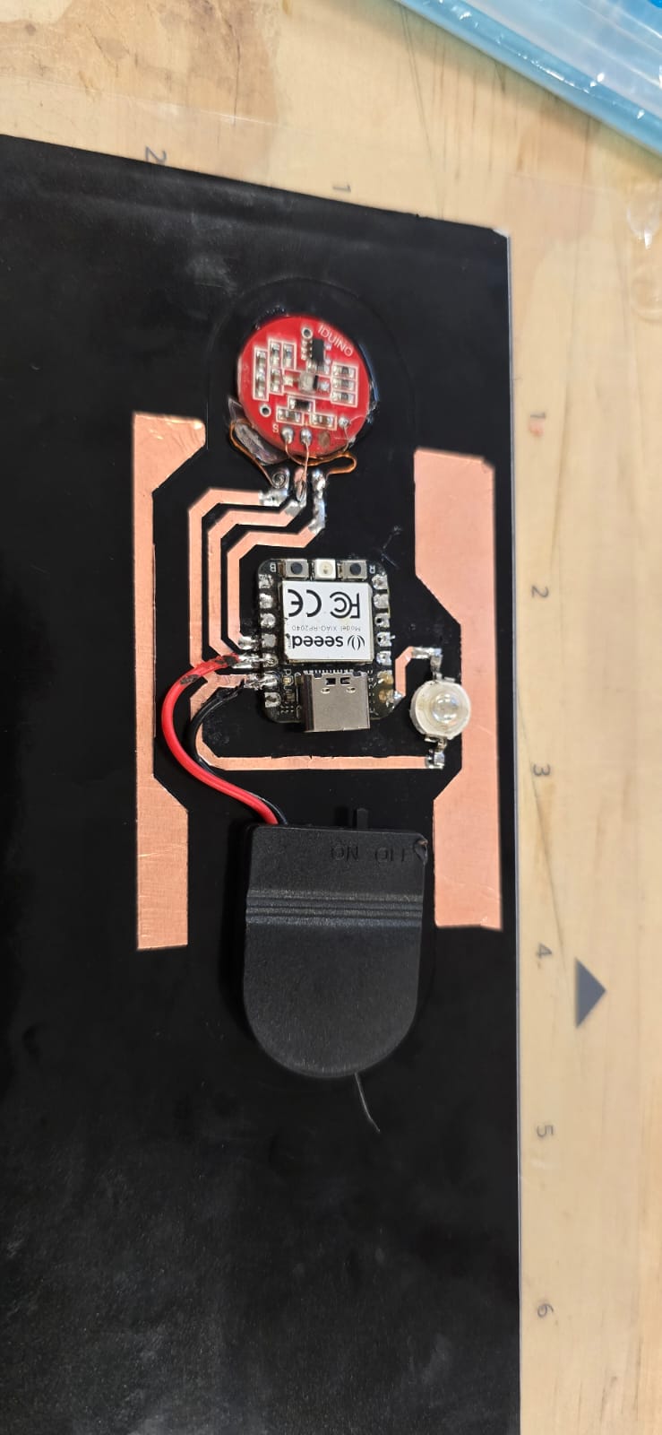
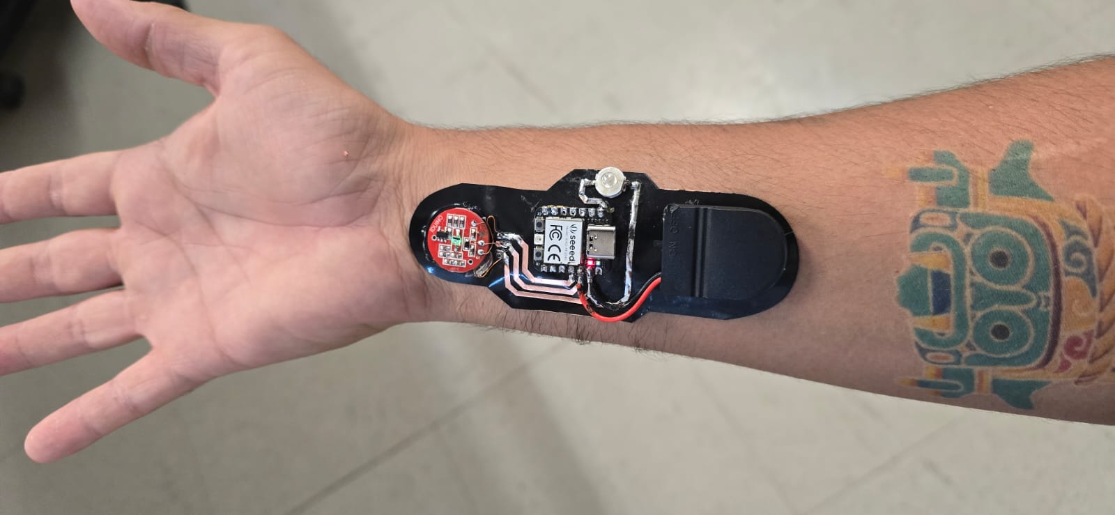
And the final E-tattoo looks like this: