11. Open Source Hardware - From Fibers to Fabric
Research & Ideation
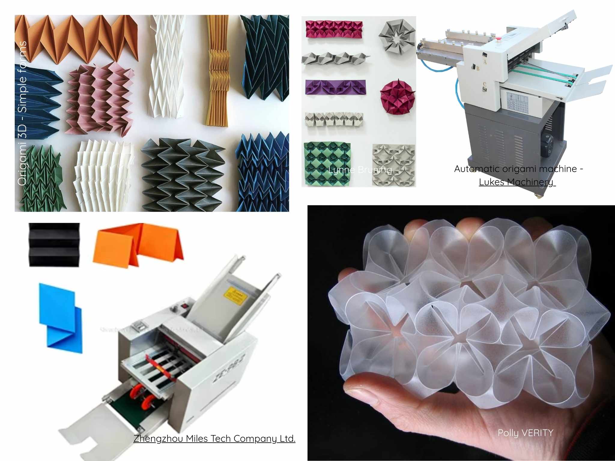
For this week's assignment, all the people at the lab worked together to build a machine for a specific task. We all gave different ideas, for example a wall painting/drawing machine, an origami scoring machine, an extrusion deposition machine, etc. and voted to get the final machine, which is a Origami scoring machine.
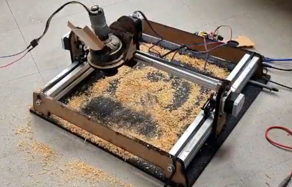
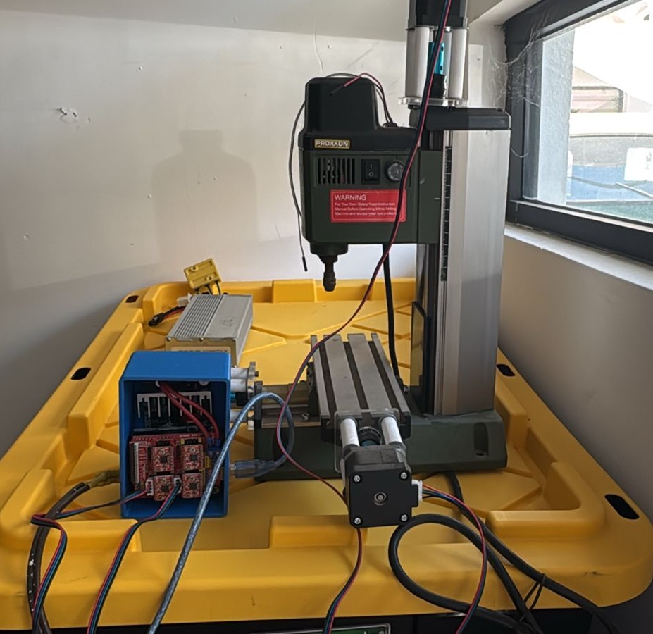
This was the 3rd time I worked on a CNC machine with my colleagues, so we didn't really start with nothing. The first time I experimented with this concept was during my FabAcademy where, as a team created a powder deposition machine, to recreate the traditional powder carpets done in several places in México. The second approach I had with custom made CNC machines is a small minimill I modded to work automatically through CNC. I designed and printed most of the parts for this machine to work, and got a few off-the-shelf to complement the correct functioning of the machine.
We used the principle for CNC (Computer Numeric Control) and tried (so many times) until we got it right. Let's start with the beginning.
What is CNC?
As we have been using them, all the digital fabrication machines work with this principle, which gives the machine commands on where to move, what to do while moving, and even at which speed it should be moving, with a file called Gcode. This gcode is a text file, most of the times, with hundreds of thousands of lines where it tells the machine what to do on each one. For example 3D printers move on the X, Y and Z axis and deposition material; Laser cutters move to different points and activate/deactivate the laser beam, CNC Routers move the spindle while cutting, etc.
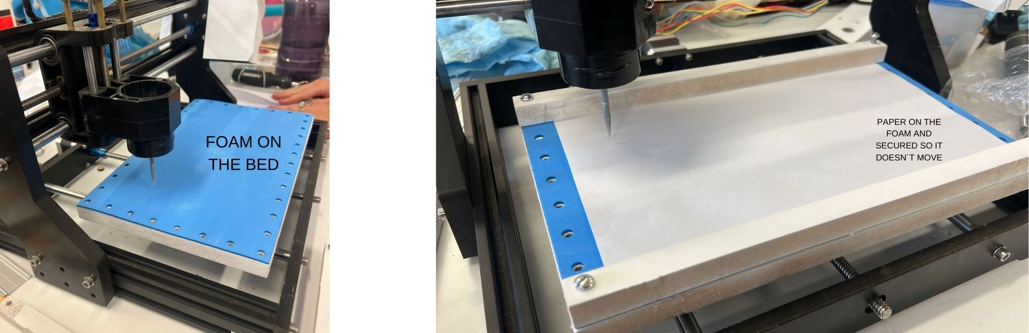
So now this machine that we are building, should score the surface of the paper, gently so it doesn´t break. The paper should be over a soft bed which allows the scoring to be deep enough, but also fixes it, so it doesn't move either.
We took some inspiration from the internet and the amazing website How to build your own CNC machine.
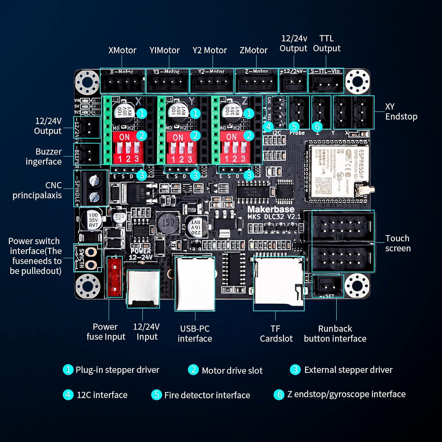
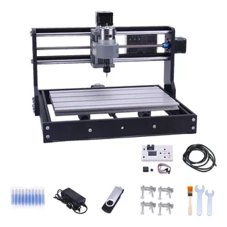
For this machine we worked with an already existing CNC controller called Makerbase, and based our design on a generic CNC Minimill for cutting PCB and carving small sculptures.
The Gcode
It was a bit difficult to wrap my head around how was de gcode going to be generated for our machine, and I thought about different alternatives:
- Create a custom 3D printer in Ultimaker Cura, and it was important that it could do a little hop on the z-axis everytime. The problem is that Cura is expecting a 3D model, or an image and not some vectors.
- Treat the gcode as a laser gcode but instead of activating/deactivating the laser, moving the pen up and down accordingly, but that was also very hard to do as it was necessary to modify the export code and syntax.
- Use the InkScape extensions for vinyl cutting and treating our machine as a vinyl cutter, as it works similarly to the origami machine.
- Treat the machine as a drawing machine, but instead of a pen, we use the pointy tool for denting the surface of the paper.
- Treat the machine as a CNC Router without a spindle and hope for the best.
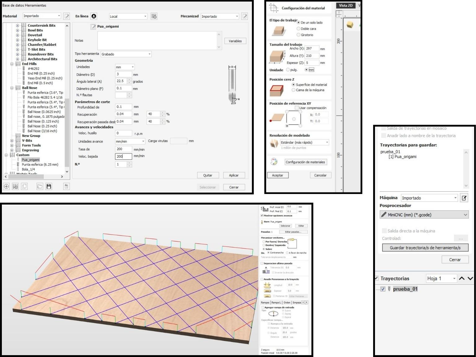
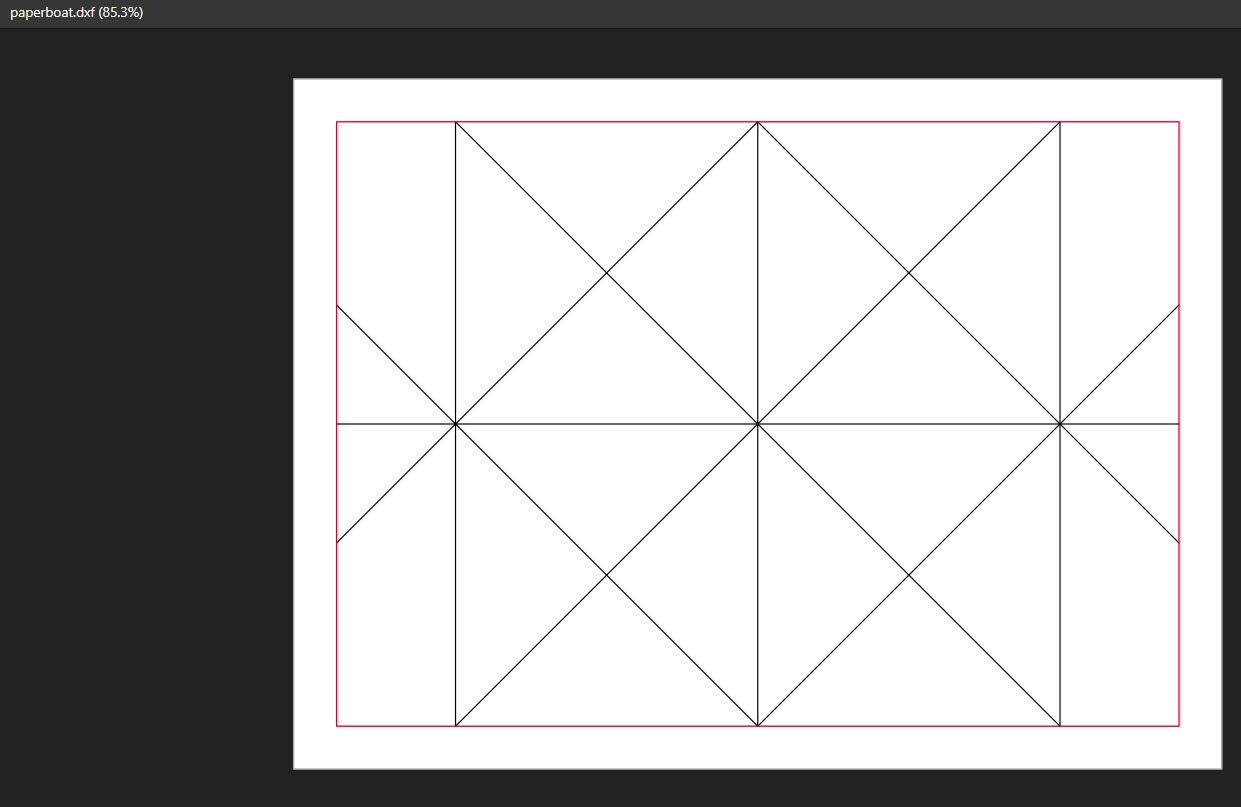
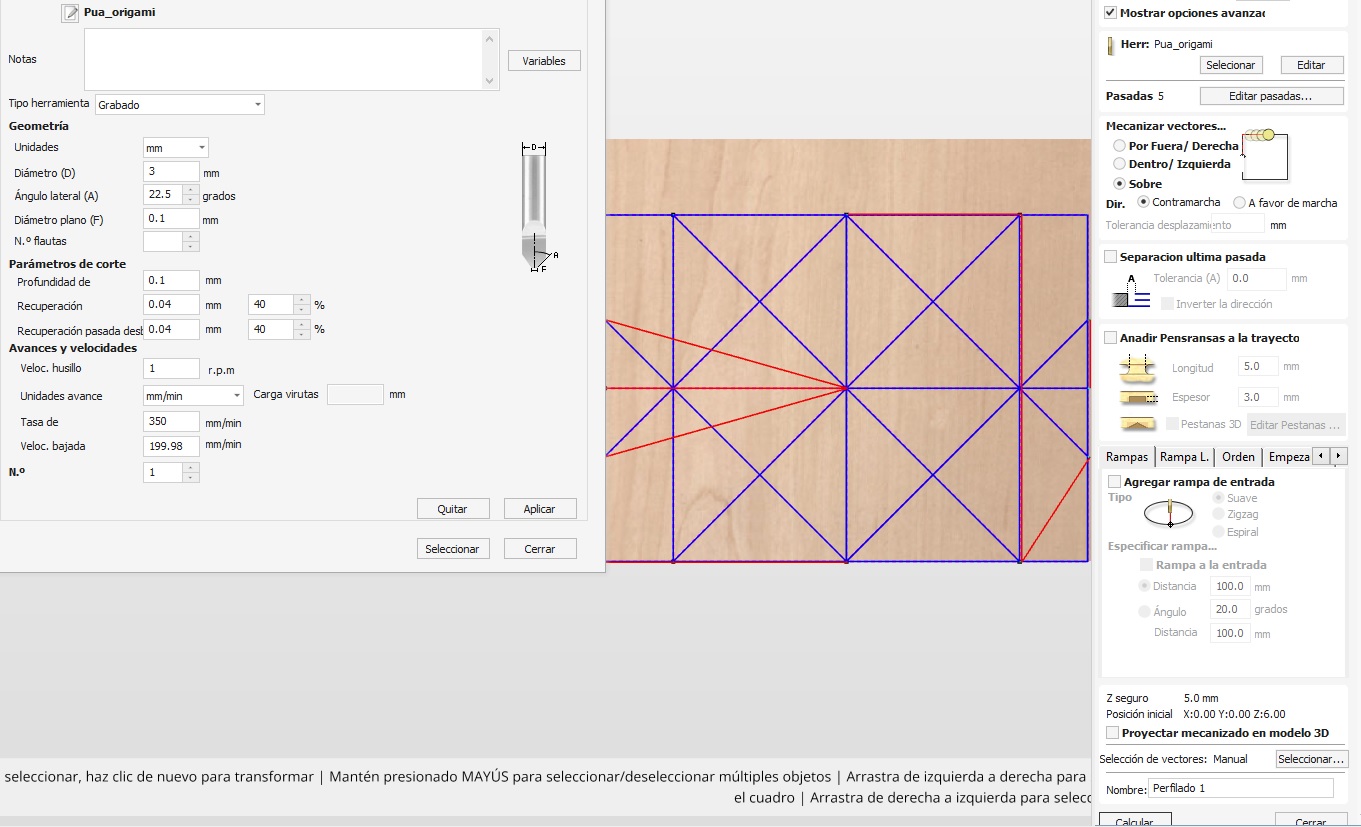
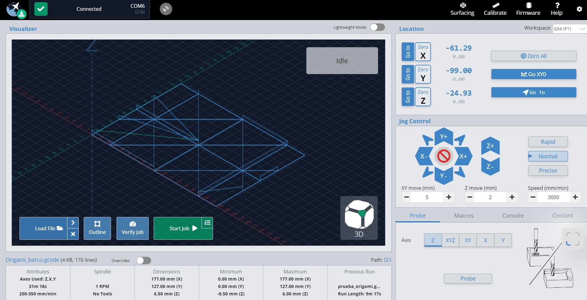
After thinking about the solutions, pros and cons of each one, and doing some research online, the best option is the CNC router imposter, as the Vectric Vcarve software is optimized for this kind of paths and operations. The design was drawn in Inkscape as a vector and exported in .dxf format. Then uploaded to Vcarve for the proper configuration. A new tool was created for this operation, which needs 0 rpm and a slow feed rate, little depth per pass, etc. The final gcode was exported and tested on the open-source software Gsender, which can control the machine. The first step with the Gsender is to zero every axis with the Zero X, Zero Y and Zero Z buttons, while having moved the tool to the lower-left corner of the area. I ran some tests high enough, so the tool doesn’t touch the base, and voilá! It worked.
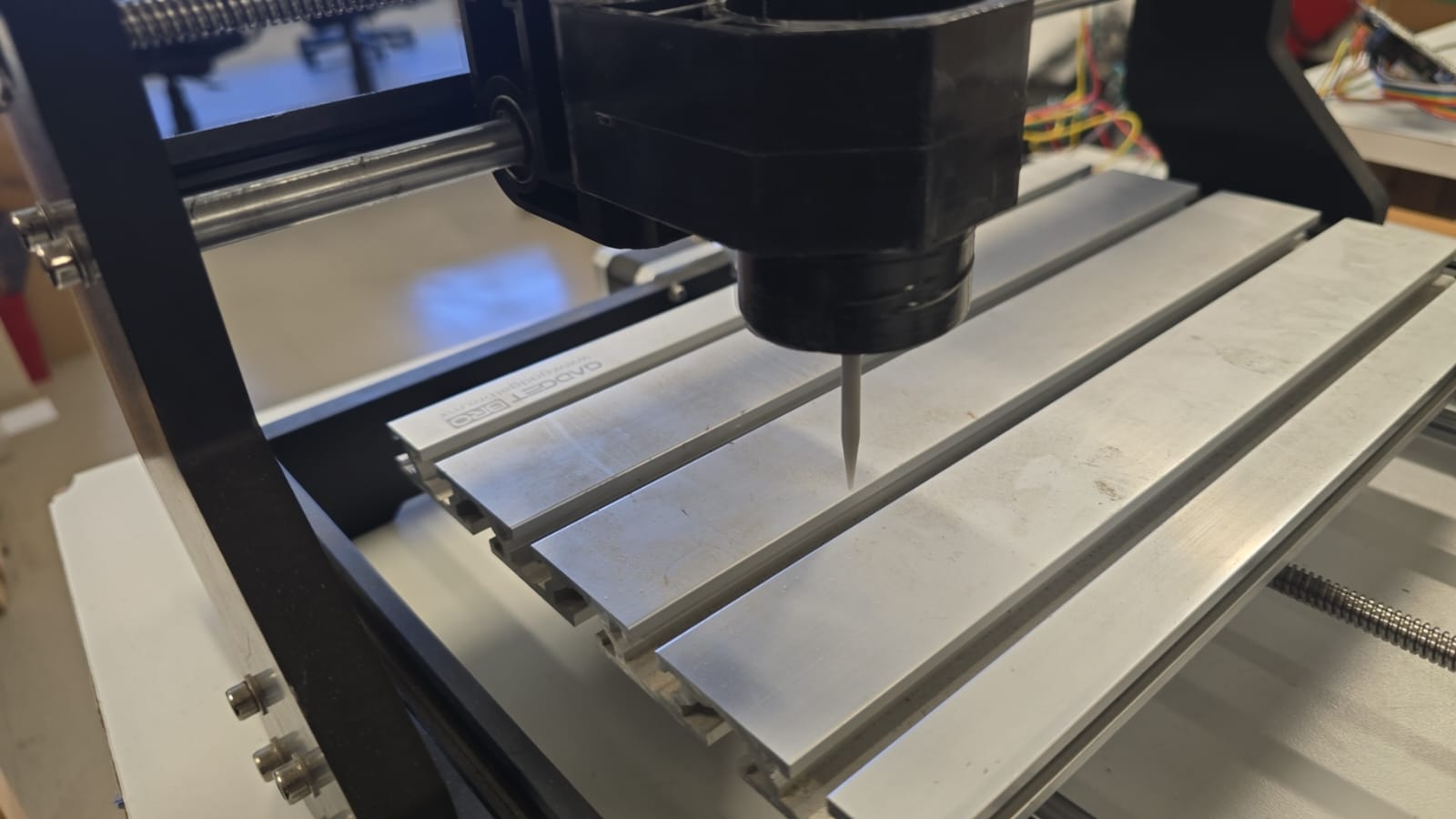
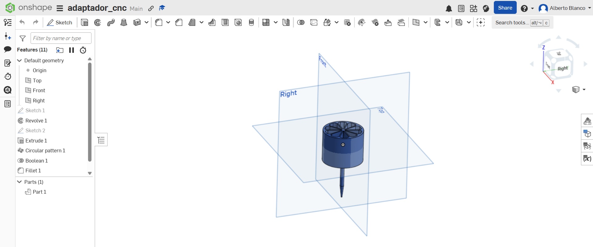
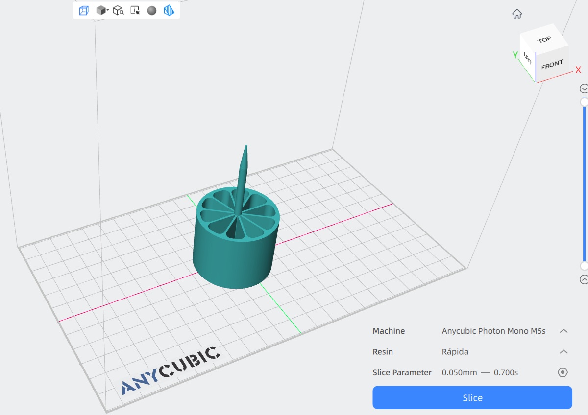
Also the adapter tool for scoring was designed with Onshape and printed in resin for resistance. It was designed to fit in the hole for the spindle, so we needed the least modifications on the machine. The shaft/spike done very long on purpose to be as high and low as possible without interfering with the movement of the machine, while mantaining contact with the paper.
The resin that was used is the Anycubic high speed resin 2.0 which, according to the online documentation, should work with the following parameters: * Layer height: .1mm * Normal exposition time: 2.8s * Light-off time: .5s * Base layers: 5 * Base exposition time: 25s * Printing temperature: 20°-50°C
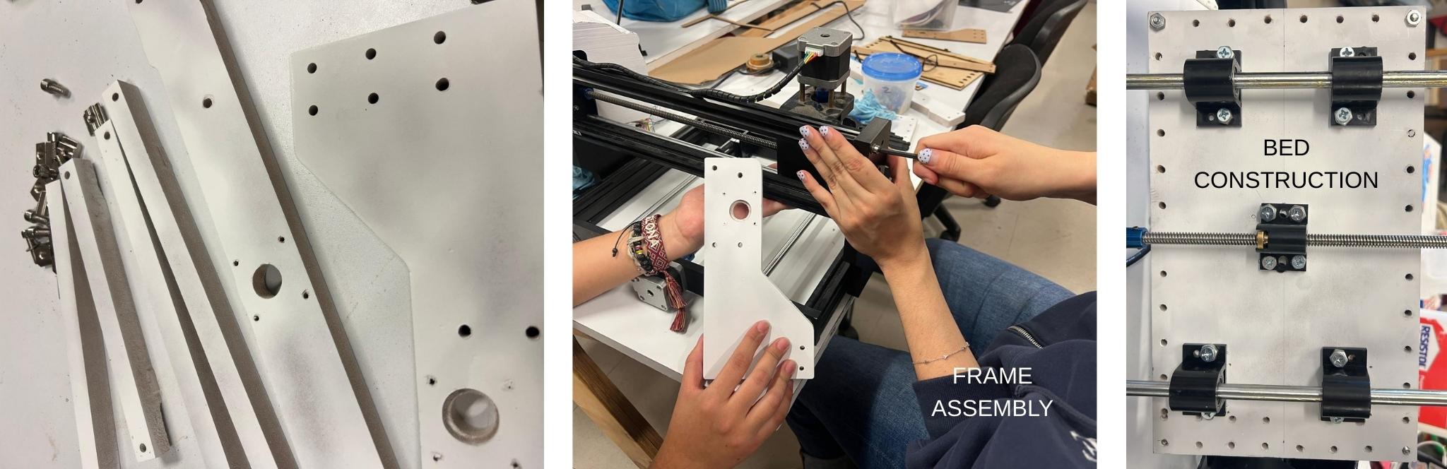
The machine
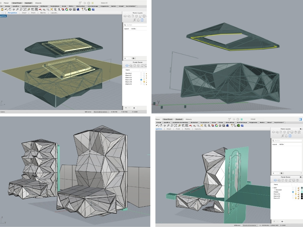
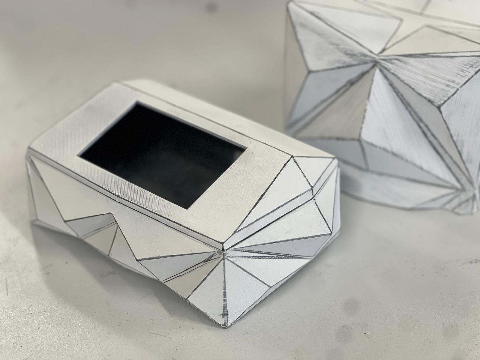
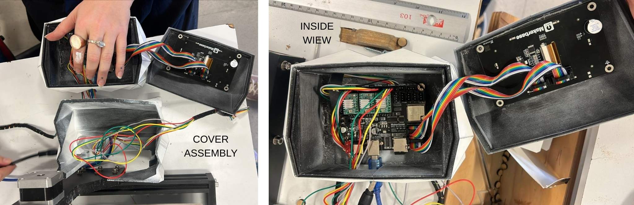
We modified the original machine for our purpose, and even redesigned and built a case. The software, machines and parts that were used for the fabrication of this machine are the following:
Software
| Software | Use | Step |
|---|---|---|
| ChatGPT | Concept development, ideation for machine design & cover | Research & Ideation |
| Studio Tripo 3D | 3D modeling & form exploration | Design Development |
| Rhino 3D | 2D/3D modeling of machine parts, bed, frame & design elements | Design Development |
| OnShape | 3D modeling of machine parts | Design Development |
| VCarve (Vectric) | CAM software for toolpath creation & CNC preparation | Toolpath Generation |
| Ultimaker Cura | Testing alternative CNC workflows & G-code logic | Workflow Exploration |
| Universal Gcode Sender | Sending, controlling & testing G-code on the CNC machine | Machine control & testing |
| Gsender | Sending, controlling & testing G-code on the CNC machine | Machine Control & Testing |
| Photoshop | Image editing & documentation visuals | Documentation |
Machines/Hardware
| Machine/Hardware | Use | Step |
|---|---|---|
| ASIA Robotica CNC Router | Reference CNC system & fabrication benchmark | Research & Learning |
| Laser Cutter | Cutting initial bed & frame prototypes | Prototyping |
| Resin 3D Printer | Fabrication of the punch / marking tool | Tool Fabrication |
| 3D Printer | Fabrication of the cover | Machine Cover |
| Hand Tools (clamps, saws, etc.) | Assembly, adjustments & finishing | Assembly & Finishing |
Parts
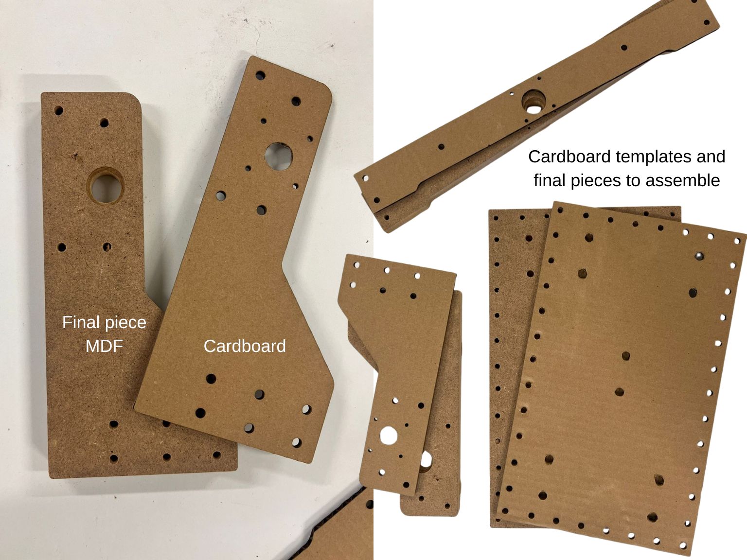
| Material | Use | Step | Cost| |------|------|------| | MDF / Plywood | Bed, frame & structural parts of the machine | Bed / Frame Construction | $7.50 (USD) | | Foam Board / Foam Sheets | Soft support layer to allow clean scoring without tearing | Bed Assembly | $2 (USD) | | Resin (3D printing) | Fabrication of the punch / marking tool | Tool Fabrication | $13.50 (USD) / kg | | PLA Filament | 3D-printed machine parts, cover & prototypes | Prototyping | $15 (USD) / kg | | Screws & Bolts | Mechanical assembly of machine components | | $10 (USD) | | Wood Glue | Joining MDF / plywood layers | Assembly | $10 (USD) / kg | | Paint (white) | Surface finishing of the machine cover | Cover Finishing | $14.50 (USD) | | Sandpaper | Surface smoothing & finishing | Finishing | $0.50 (USD) | | Electrical Wires & Connectors | Power & signal connections | Electronics Assembly | $5 (USD) | | Paper (various types) | Material for origami fold testing & scoring | Testing & Evaluation | $5.50 (USD) / kg | | Makerbase controller | Motor control and gcode execution | Control | $20 (USD) |
Restults

I recommend checking my teamate's websites for this machine:
Challenges/Failures
This machine was particularly problematic because the paper we were trying to score is quite fragile, so the force, speed and depth we worked with had to be carefully calibrated. For the great majority of tests, these were the most common problems: * The tip ripped through the paper. * The tip bent too much. * The tip scored too hard on the foam. * The depth of each pass was not enough to score the paper. * The speed in which the tip moved on the Z axis was too high and punctured through the paper. * The speed for the x and y axii was too high so the paper moved even though it was fixed to the base. * The scale of the vectors was off so the machine moved outside of its limits and made terrible noises, and decalibrated the coordinates.
How to fix all this issues?
The first part was properly calibrating the motors so, when we send te gcode for moving 1mm, all of the axii move precisely 1mm. This is done on the software Universal Gcode Sender and on the Machine menu, Firmware Settings option, there is a list of each parameter to be modified directly on the card's firmware. The ones we are looking for are (x, step/mm), (y, step/mm) and (z, step/mm) this value is modified until 1mm movements are accurate and repeatable. These parameters depend on each controller and motor model, so it is better to test, there is no universal number.
After we have precise movements on each axis, through manual movements on the interface, we could test different depths and speeds so the paper is properly scored and not ripped. These parameters work as following: * Passes: 3 * Final depth: .6mm * Depth of each pass: .2mm * X,Y feed rate: up to 250mm/min * Z plunge rate: up to 100mm/min
How does it work?
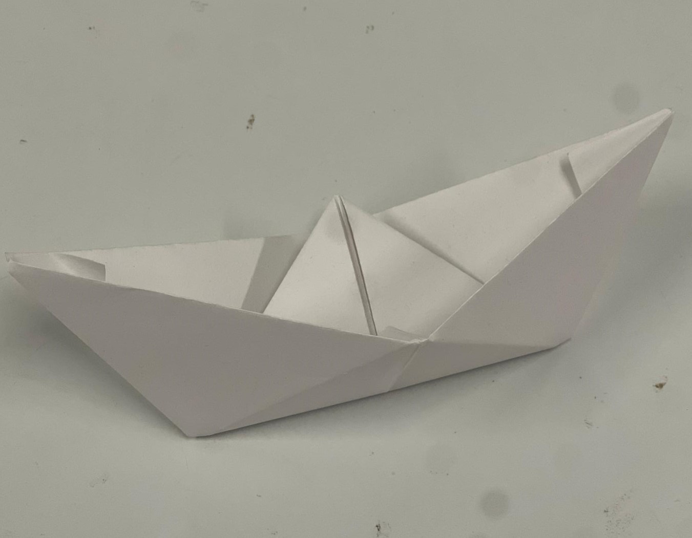
How can we get a working vector for an origami model? What we did first was fold the paper as we already knew how to create a little boat, then very carefully we unfolded it, and from those lines we traced the vector drawing that will be reproduced by the machine. Further development will make this process more intuitive, even automate it with software like Slicer for Fusion 360 or Pepakura designer. Another recommendation for this process was Origami simulator.
The process was done through Vcarve, using the custom tool we prepared, and sent as .gcode I ran it from the Gsender app, after configuring X, Y and Z axii. There will be 5 passes so the paper is perfectly scored and easy to fold afterwards.
Limitations
This machine has several limitations, as it follows: * The maximum speed of each axis is limited so the material doesn't break. * The area is limited by the movement of the motors (26cm x 14cm). * The best tests were done with cheap copy paper (around 70–80 gsm), so thicker papers are still problematic. * The process for designing the vectors is not optimized, so we are still experimenting with different software.