5. E-textiles
I. Intro
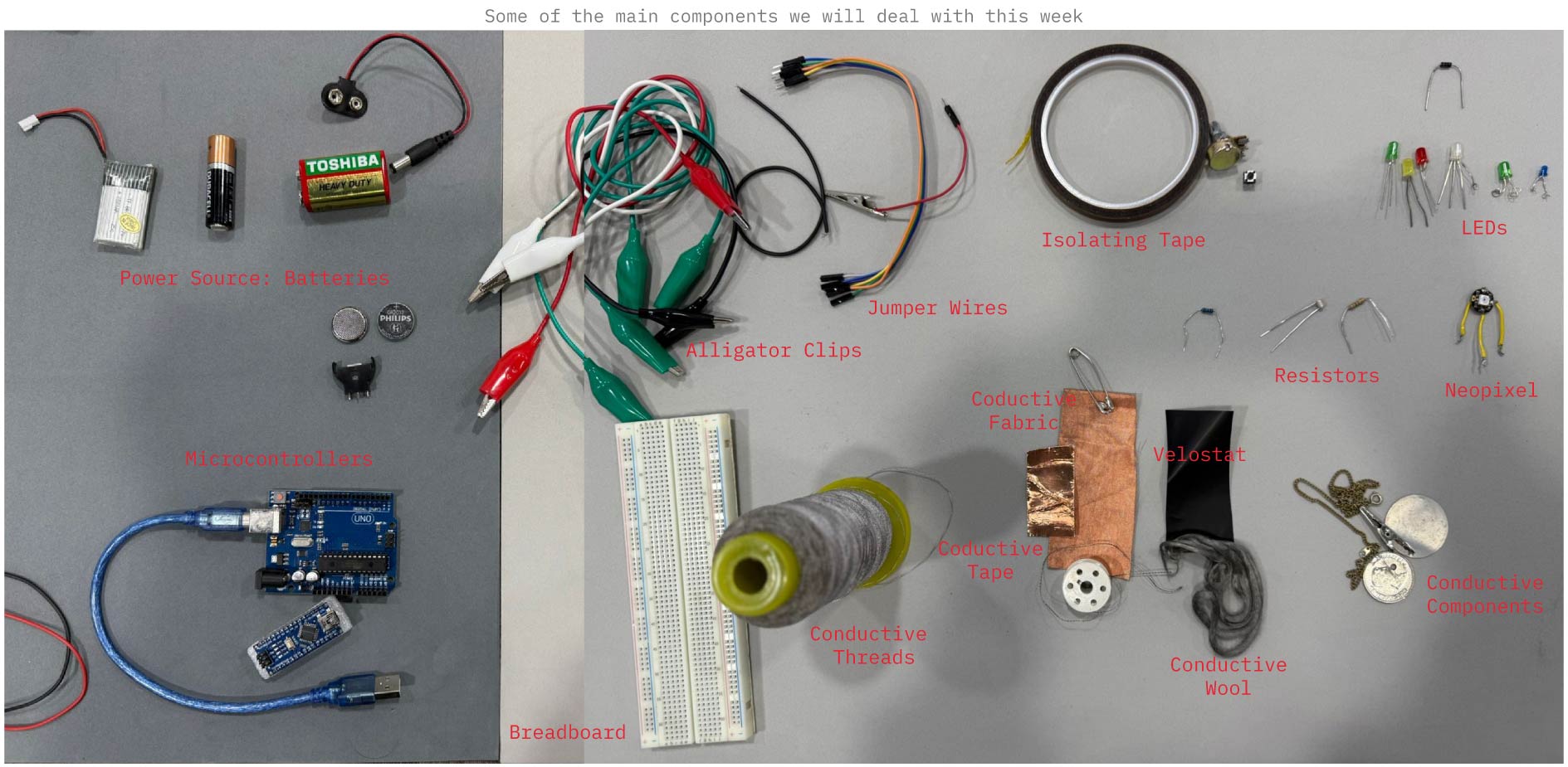
E-textiles are soft fabrics that integrate electronic components, either woven directly or indirectly into the fabric structure, allowing the textile to sense, transmit, or respond to different stimuli while serving a specific function. These components include sensors, lights, batteries, conductive threads, and microcontrollers, all of which will be introduced to throughout this week.
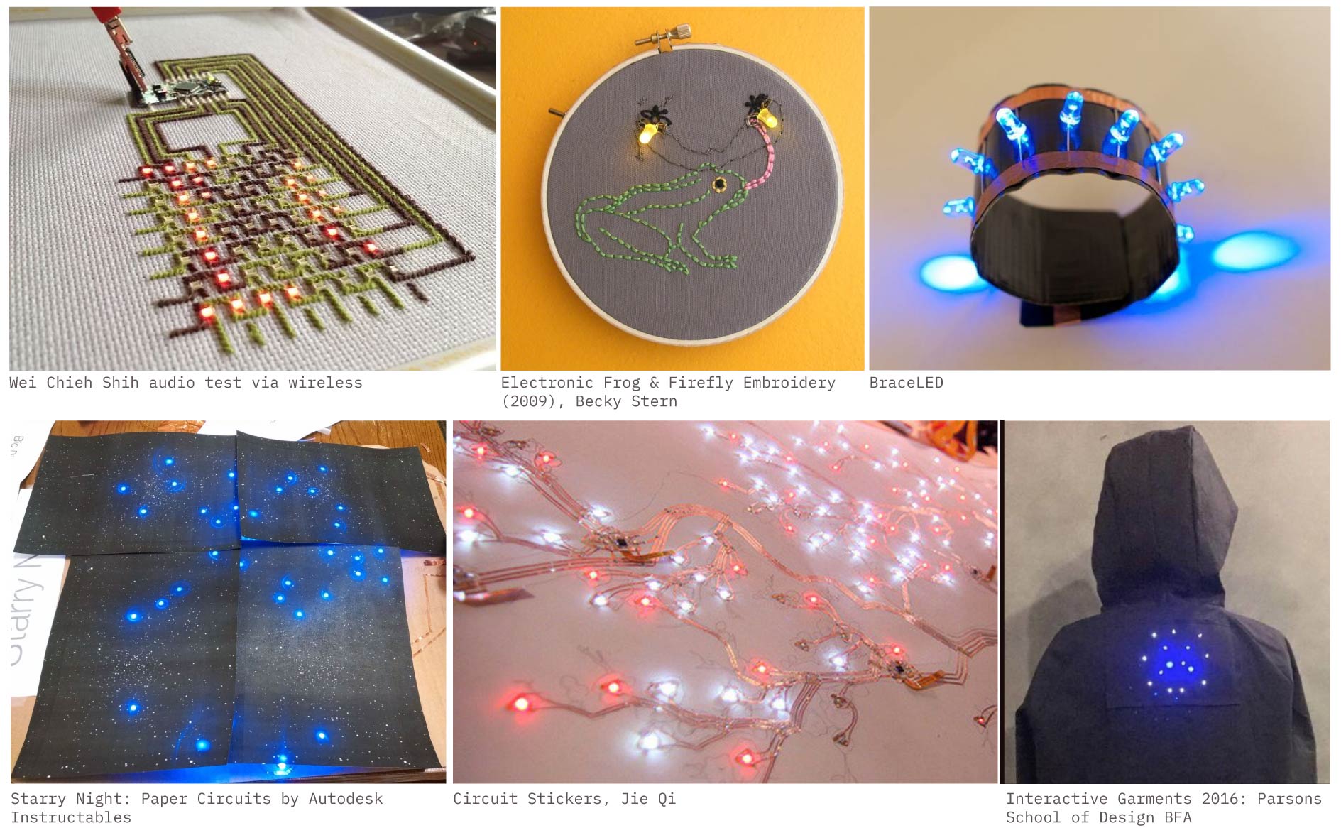
II. Inspiration and References
III. Introduction to Electronics
Let’s rewind to high school, the last time I dealt with anything related to electricity, and break things down starting from the basics.
A. Circuits
Building E-textiles in the simplest sense, means creating a circuit on the surface of a fabric to give it a specific interaction, function, or aesthetic. That’s why understanding what a circuit is, the types of circuits, and the key components that make up a circuit is essential for this week, and for many of the upcoming weeks as well.
A circuit is a path that electrical energy flows through, and this flow is called current. Every circuit has a power source with a certain voltage, and different components or boards need different voltages to work safely. So, what is voltage? Voltage is the difference in potential electrical energy measured between 2 points in a circuit. Lastly there is a third factor, the Resistance which determines how much electricity (current) flows through a circuit (measured in ohm's).
Ohm's Law states that the current flowing through a circuit is directly related to the voltage applied and inversely related to the resistance. In simple terms: higher voltage means more current, and higher resistance means less current.
It can be written as: V = I × R
V = Voltage
I = Current
R = Resistance
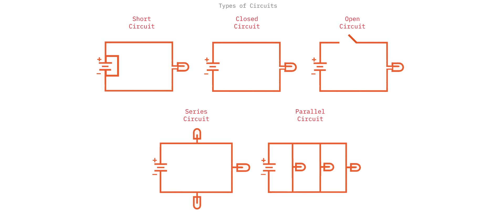
Types of Circuits
Series Circuit:
Components are connected one after another in a single path. The same current flows through all components. If one component fails, the entire circuit stops working.
Parallel Circuit:
Components are connected in multiple branches. Each component has its own path to the power source. If one component fails, the others keep working.
Open Circuit:
circuit where the path is broken, so no current flows. Like a switch in the OFF position.
Closed Circuit:
A complete path that allows current to flow. Switch in the ON position.
Short Circuit:
An unintended low-resistance path forms, causing too much current to flow. Dangerous can cause overheating or damage.
Main Components of a Circuit
Power Source:
Provides the electrical energy.
Examples: Battery, USB power, power supply.
Conductive Path:
The material that carries the electric current.
Examples: Wires, copper traces, conductive thread, conductive tape.
Load (Output):
Anything that uses the electrical energy to do work.
Examples: LEDs, motors, speakers, sensors, microcontrollers.
Switch:
Controls the flow of electricity by opening or closing the circuit.
Examples: Button, toggle switch, pressure switch, fabric snap switch.
Resistor:
Limits the amount of current to protect components.
Example: LED always needs a resistor in basic circuits.
Microcontroller (optional but common):
A small programmable “brain” that controls how components behave.
Examples: Arduino UNO, Seeed XIAO.
Remember!
If the path is closed, electricity flows, the components work. If the path is open (disconnected anywhere), no electricity flows. The current moves from (+) power to (-) ground.
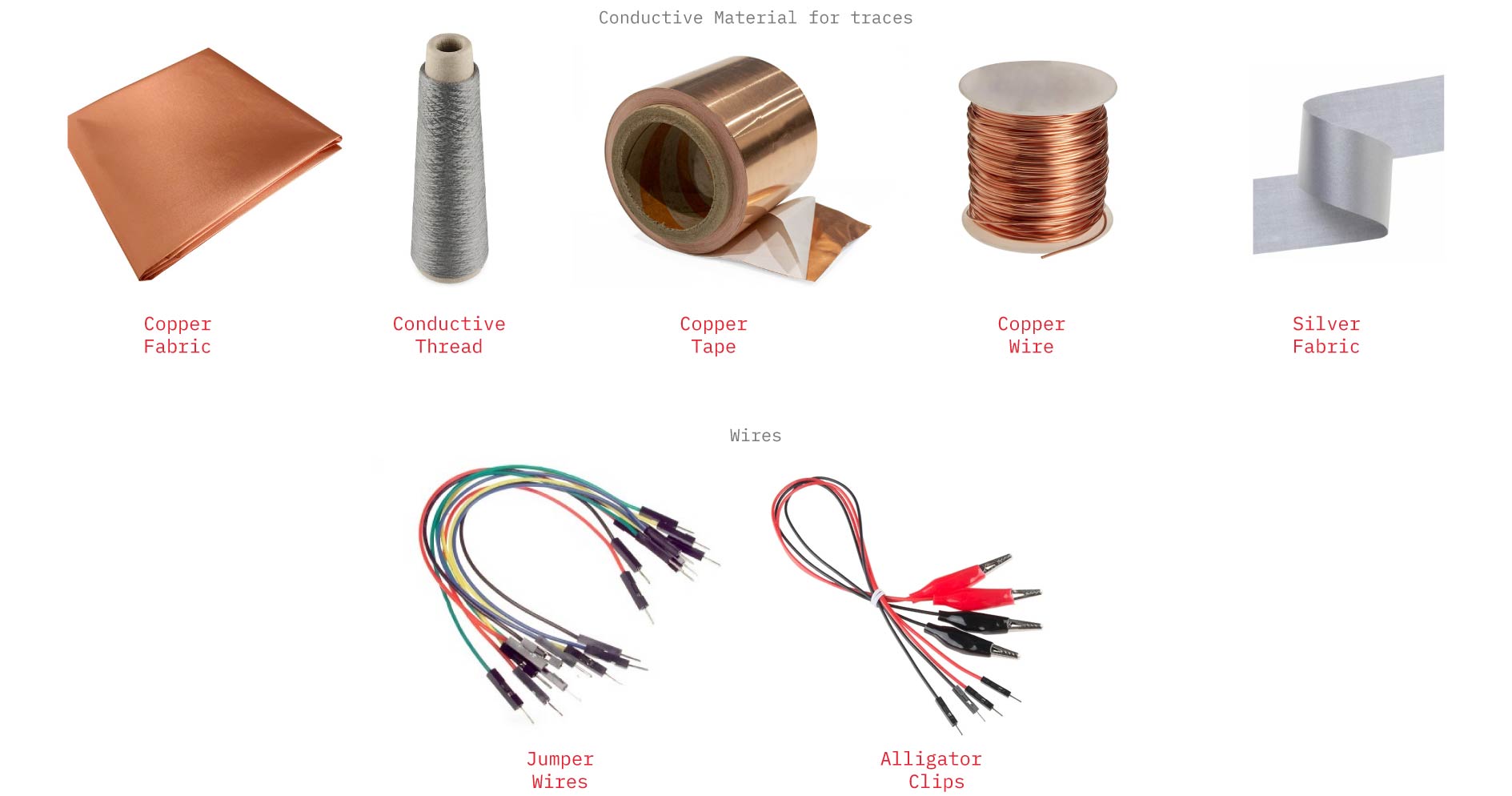
B. Traces
Traces are the conductive paths in a circuit that allow electric current to move between components. They can be made using wires, jumper wires, alligator clips, conductive thread, or even stitched conductive fabric.
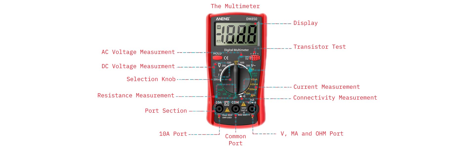
C. The Multimeter
While building the circuit, we should constantly check that all the components are perfectly connected, and here comes the Multimeter, a handheld tool used to measure electrical values in a circuit, such as voltage, current, and resistance. It helps you check whether a circuit is working properly and diagnose issues or incorrect connections.
D. Outputs
Outputs are the parts of a circuit that produce an action, signal, or effect based on the electrical energy they receive.
They respond to the input or the code by: lighting up, making sound, moving, showing data, activating something.

LEDs (Light-Emitting Diodes) are electronic components that emit light when an electric current passes through them.
About LEDs
They use very little energy.
They come in different colors and sizes.
They must be connected in the correct direction (LED has a positive leg (anode) and negative leg (cathode)).
They usually need a resistor so they don’t burn out.
Common Examples of Outputs
LEDs and Neopixels → light output
Servo motors → movement output
DC motors → rotation output
Buzzers / speakers → sound output
Displays (OLED, LCD) → visual output
Heating elements → heat output
E. Microcontrollers
A Microcontroller is a tiny computer on a single chip that can read inputs, run code, and control outputs in a circuit.
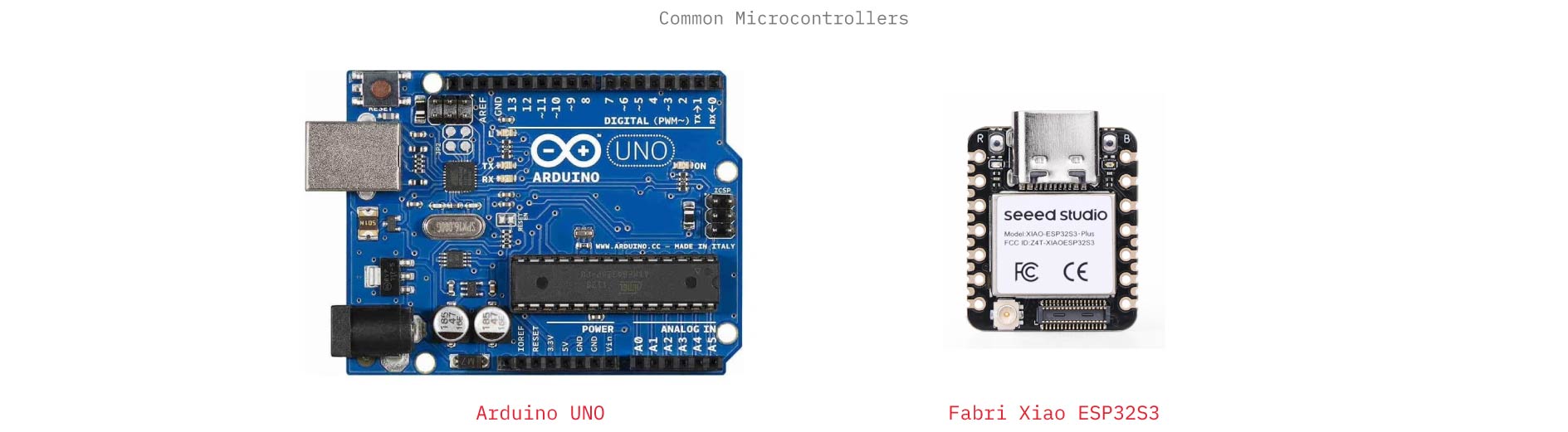 Common examples:
Arduino Uno is a small programmable electronic board based on a microcontroller that lets you connect sensors and outputs to build interactive projects.
Arduino Uno Includes
ATmega328P microcontroller
Power from USB or battery
14 digital I/O pins
6 analog input pins
Built-in reset button
Voltage regulator
Seeed Studio XIAO Seeed Studio XIAO is a series of tiny microcontroller development boards made by Seeed Studio. They include a powerful processor, memory, USB connection, and input/output pins on a board roughly the size of a coin, making them ideal for wearables, compact prototypes, and e-textile projects.
Setting up a Microcntroller on Arduino IDE
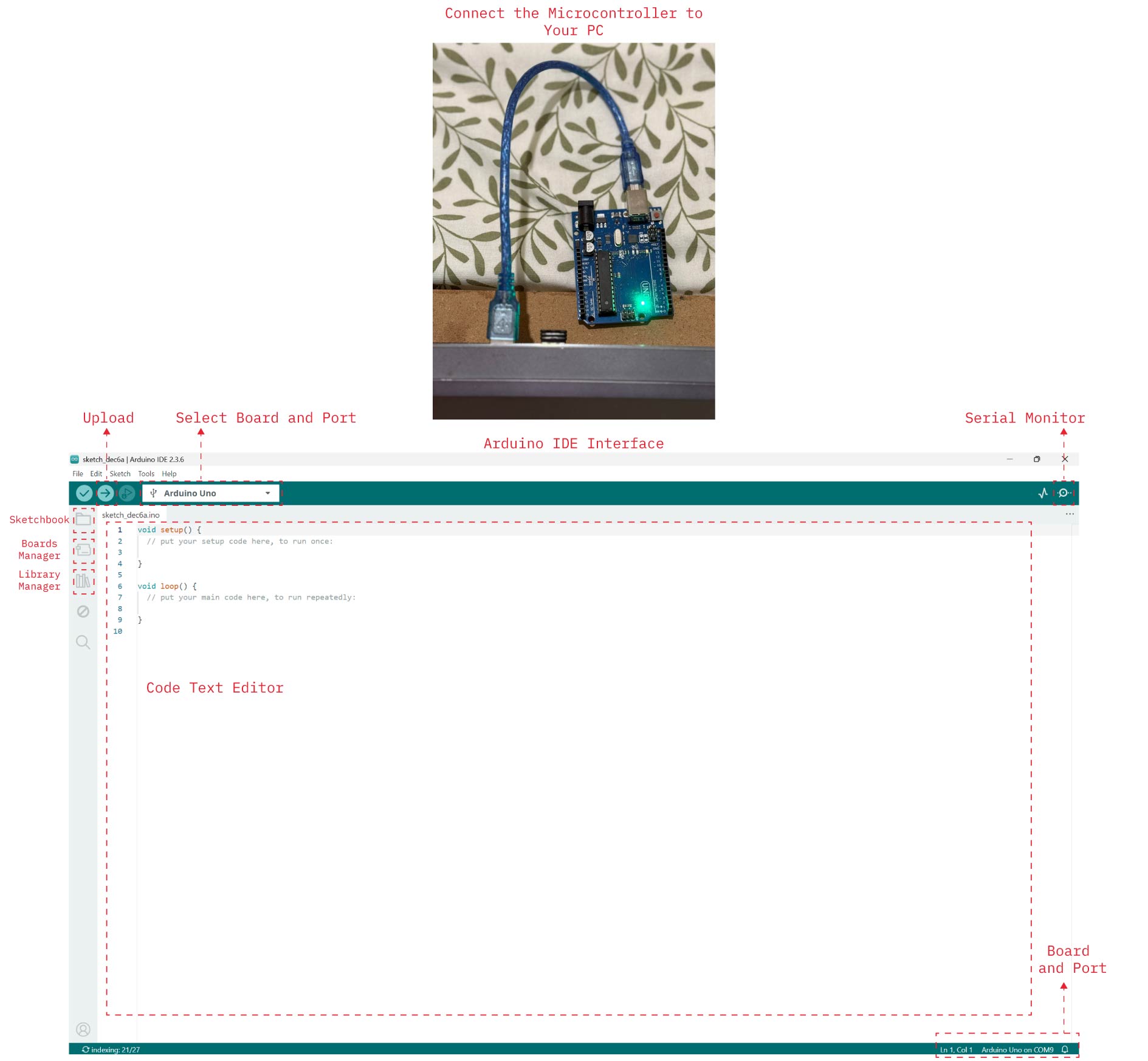
Steps of Setting Microcontroller on PC
-
Install the Arduino IDE: Go to the Arduino website, download the Arduino IDE for your operating system, install it normally.
-
Connect the Microcontroller to Your PC, use the correct USB cable, the power LED on the board should turn on.
-
Install Drivers (If Needed), Arduino Uno usually installs automatically, for Seeed Studio ESP32S3 follow the installation instructions in my documentation of Wearables Week.
-
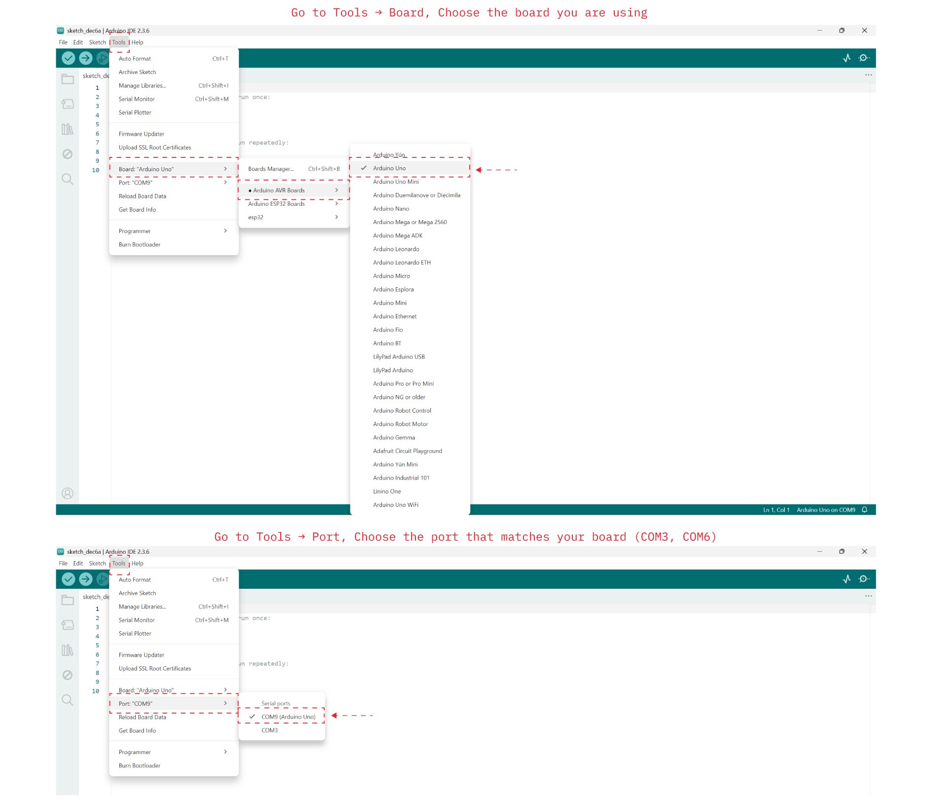
Open Arduino IDE, Go to Tools → Board, Choose the board you are using.
-
Select the Port, Go to Tools → Port, Choose the port that matches your board (COM3, COM6), If no port shows either try another USB cable or another port and if it still doesn't work reinstall drivers.
-
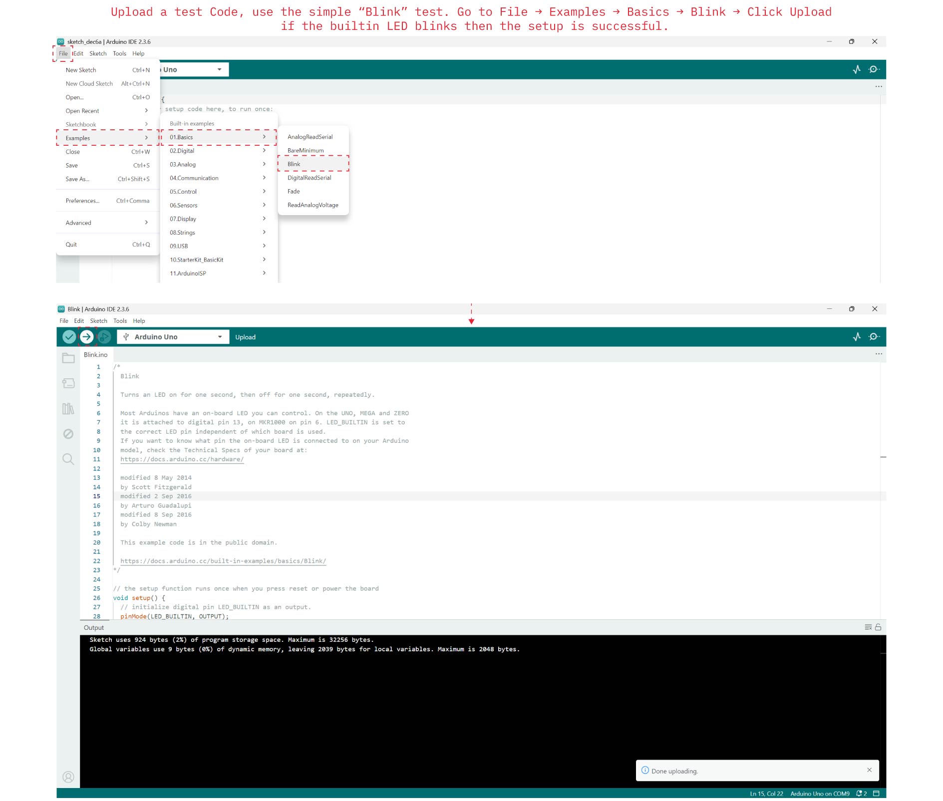
Upload a test Code, use the simple “Blink” test. Go to File → Examples → Basics → Blink → Click Upload (right arrow icon), if the builtin LED blinks then the setup is successful.
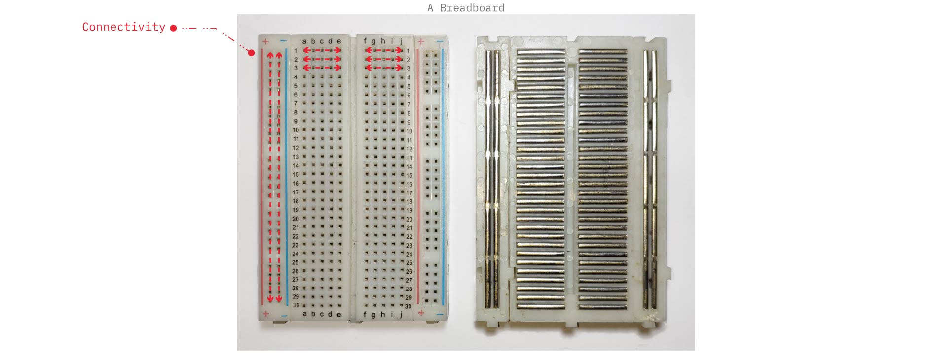
F. Breadboards
A breadboard is a reusable prototyping board that allows electronic components to be connected and tested without soldering. It uses internal metal strips to temporarily connect components
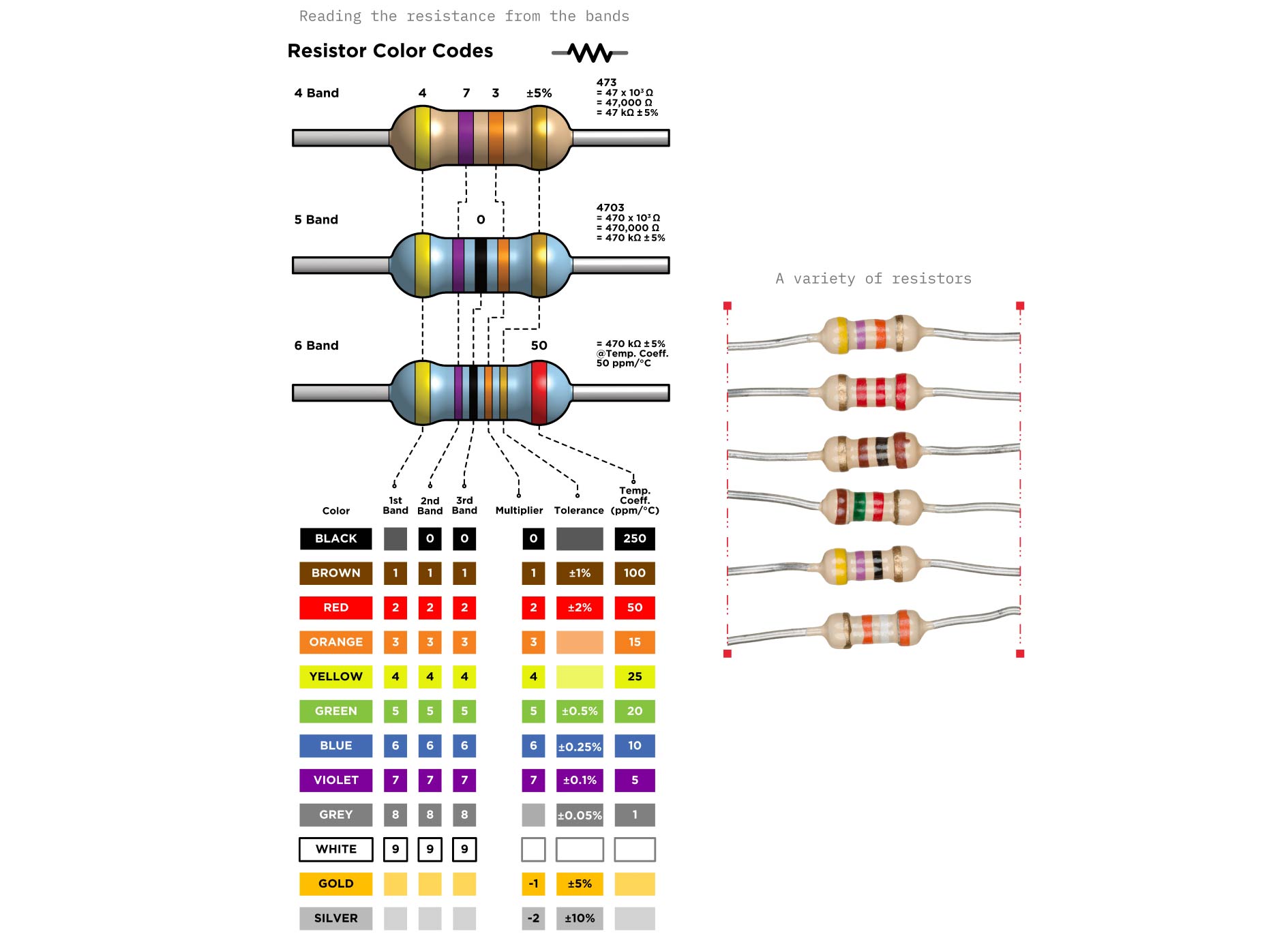
G. Resistors
A resistor is an electronic component that limits the flow of electric current in a circuit. It is used to protect components, control voltage and current levels, and ensure a circuit operates safely. Resistors have no polarity.
IV. Building the First Circuits
Now comes the moment where theory turns into a little bit of magic.
1. Simple Circuit: Blink Blue LED
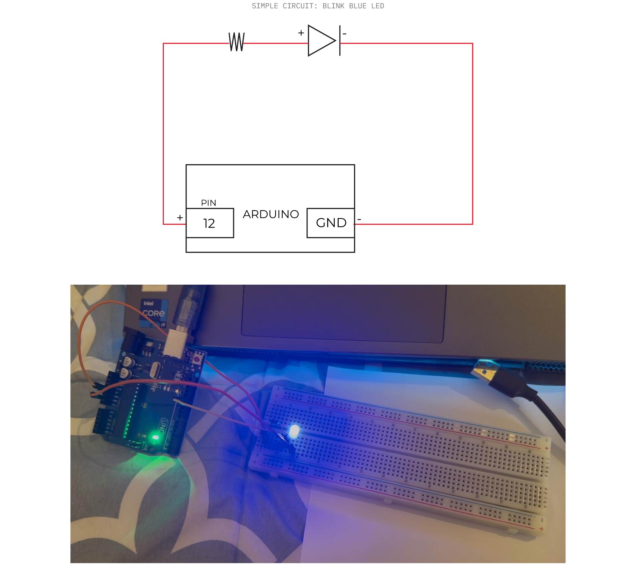
Arduino Code
void setup() {
  // initialize digital pin LED_BUILTIN as an output.
  pinMode(12, OUTPUT);
}

// the loop function runs over and over again forever
void loop() {
  digitalWrite(12, HIGH);  // turn the LED on (HIGH is the voltage level)
  delay(200);                      // wait for a second
  digitalWrite(12, LOW);   // turn the LED off by making the voltage LOW
  delay(200);                      // wait for a second
}
Result
2. Simple Circuit: Blink 2 Leds in Parallel Connection
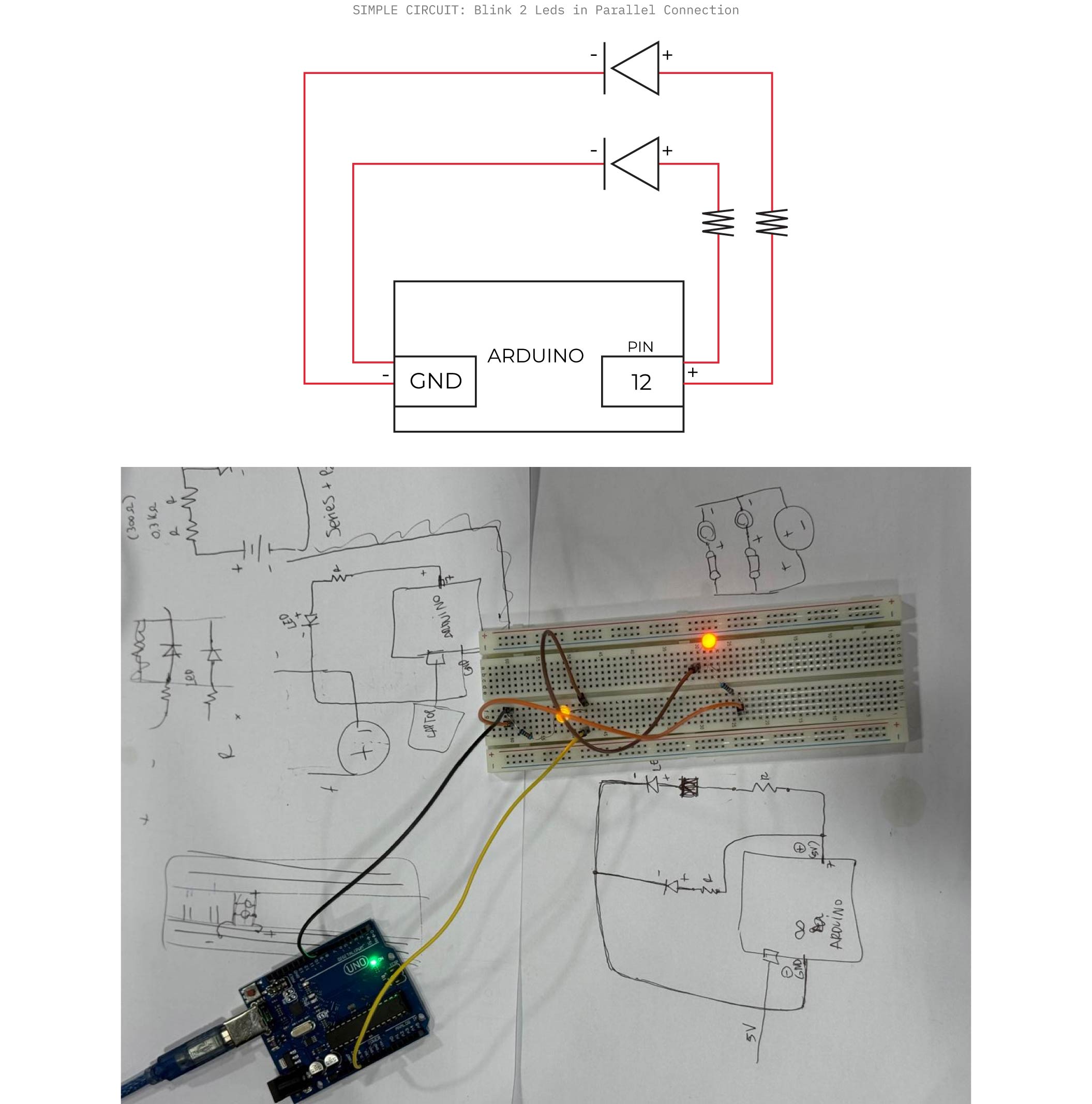
Arduino Code
void setup() {
  // initialize digital pin LED_BUILTIN as an output.
  pinMode(12, OUTPUT);
}

// the loop function runs over and over again forever
void loop() {
  digitalWrite(12, HIGH);  // turn the LED on (HIGH is the voltage level)
  delay(200);                      // wait for a second
  digitalWrite(12, LOW);   // turn the LED off by making the voltage LOW
  delay(200);                      // wait for a second
}
Result
V. Input Components: Digital vs. Analog Switches
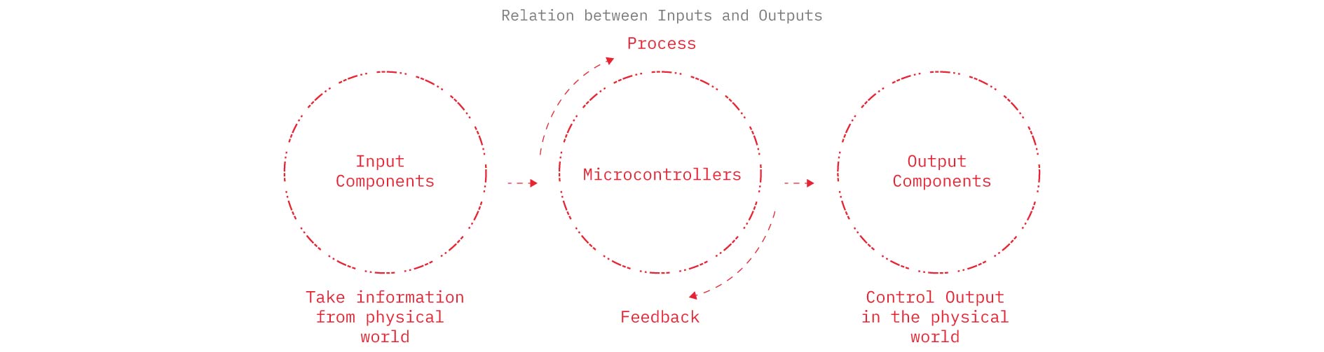
Input components are parts of a circuit that detect or measure something from the environment and send that information to the microcontroller.
1. Digital Switch
A digital switch is a component that changes the circuit between two states ON or OFF and sends a simple binary signal (HIGH or LOW) to the microcontroller, common example: Push Button.
About Digital switch
- Only two possible outputs:
ON / OFF
HIGH / LOW
1 / 0
-
Arduino reads it with digitalRead()
-
Connects to digital pins
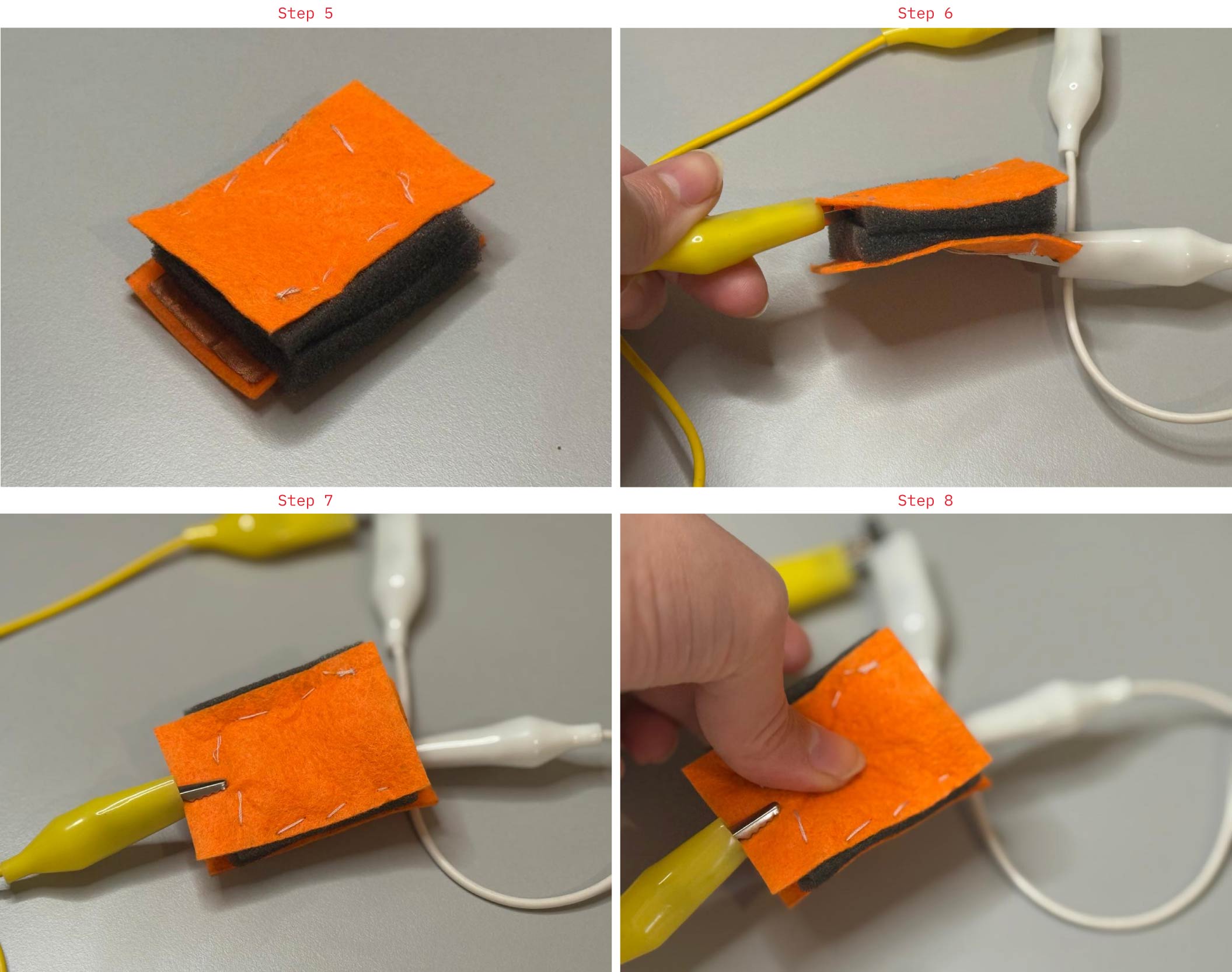
Building Digital Switch Workflow
Step by Step
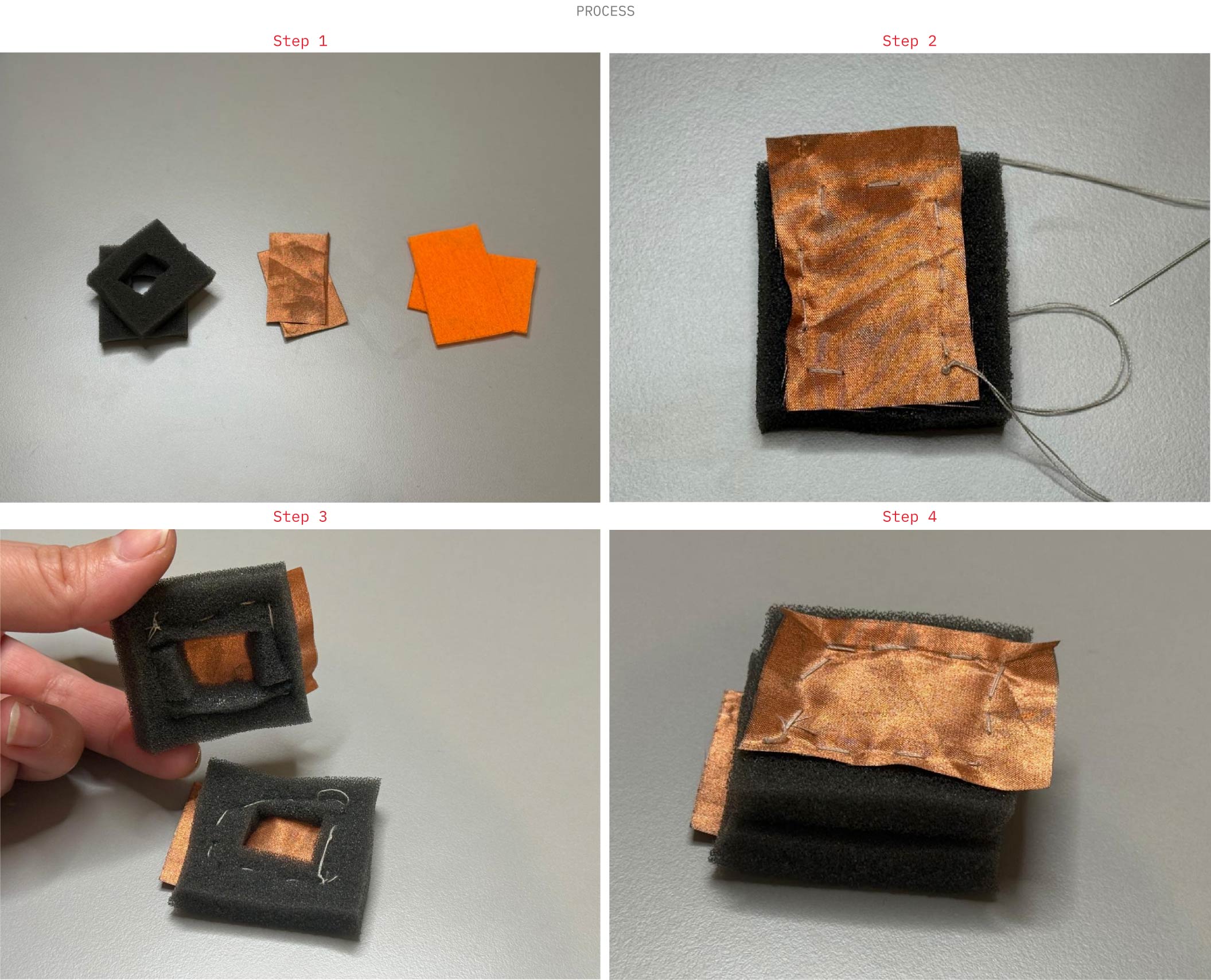
1- Prepare the materials

Cut: Two conductive fabric pieces (copper fabric), Two foam spacers (with a square hole in the center), Two outer fabric layers (felt or textile)

2- Create the bottom layer: Place one conductive fabric piece on top of a felt base layer. Stitch or fix it in place, leaving a small extension for electrical connection.

3- Add the spacer layer: Position the foam spacer with the cut-out opening on top of the conductive layer. This gap prevents contact when no (pressure) is applied.

4- Prepare the top conductive layer: Attach the second conductive fabric piece onto another textile layer (top layer).Ensure it aligns with the opening in the foam spacer.

5- Assemble the sandwich structure:

Stack the layers in this order:

Bottom textile + conductive fabric

Foam spacer

Top conductive fabric + textile

6- Secure the layers: Stitch around the edges to hold everything together, keeping the center area flexible.

7- Attach connections: Connect wires (or crocodile clips) to the exposed conductive fabric tabs on both layers.

8- Test the sensor

Without pressure → layers are separated → OFF (LOW / 0)

With pressure → conductive layers touch → ON (HIGH / 1)
Connect the digital switch to the circuit:
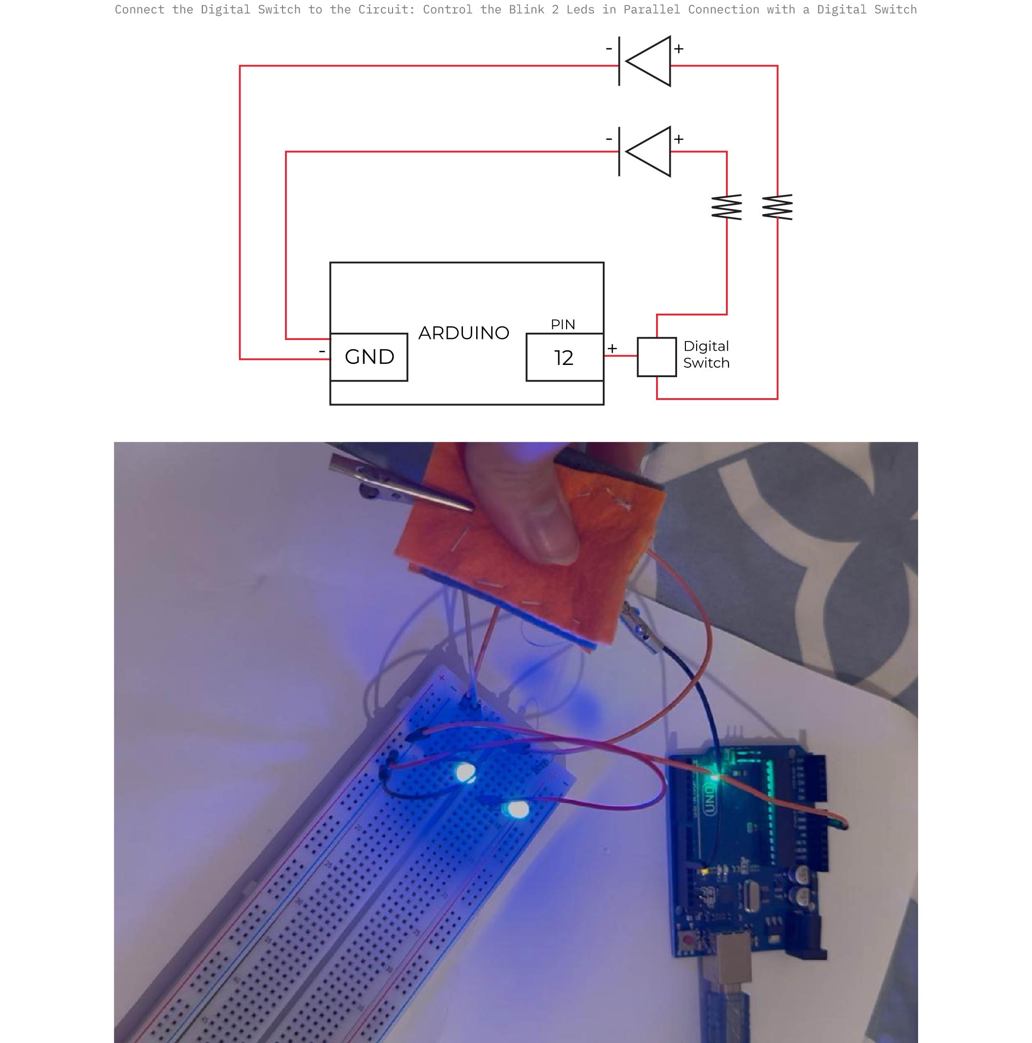
The Arduino code is the same as the one used in the other 2 examples for the blink.
Result
2. Analog Switch (Sensor)
An analog sensor is a component that measures a changing physical condition (like light, pressure, bend, or temperature) and outputs a continuous electrical signal that the microcontroller can read as a range of values. It tells the board how much not just yes/no.
About Analog Sensor
- Continuous range of values (not just two states):

LOW → HIGH (variable signal)

0 → 1023 (on Arduino)

- Arduino reads it with analogRead()

- Provides varying voltage depending on input (e.g. light, temperature, pressure)

- Connects to analog pins (A0, A1, A2, …)
Building Analog Pressure Sensor Workflow
Step by Step
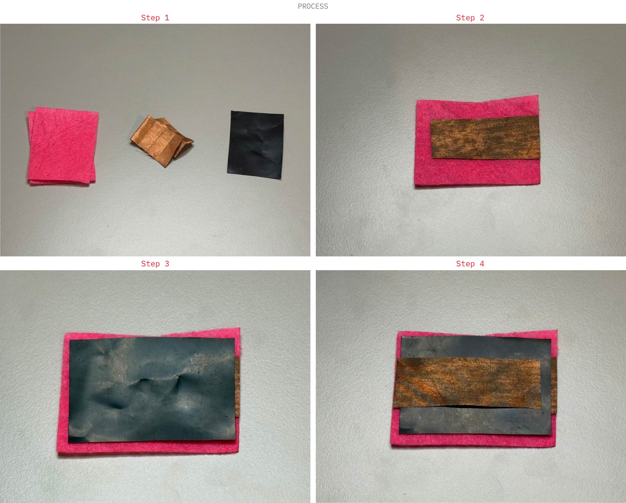
1- Prepare the materials
Cut: Two outer fabric layers (felt), Two pieces of conductive fabric (copper), One piece of Velostat
2- Create the bottom layer: Place the conductive fabric strip onto one felt piece (this acts as the first electrode). Leave a small tab exposed for connection.
3- Add the resistive layer: Place the resistive material (Velostat) on top of the conductive layer. This layer changes resistance when pressure is applied.
4- Add the top electrode: Place the second conductive fabric piece on top of the resistive layer, aligned with the bottom electrode (without directly touching each other).
5- Close the structure: Cover with the second felt layer to create a soft sandwich structure.
6- Secure the layers: Stitch around the edges to hold all layers together while keeping the center flexible.
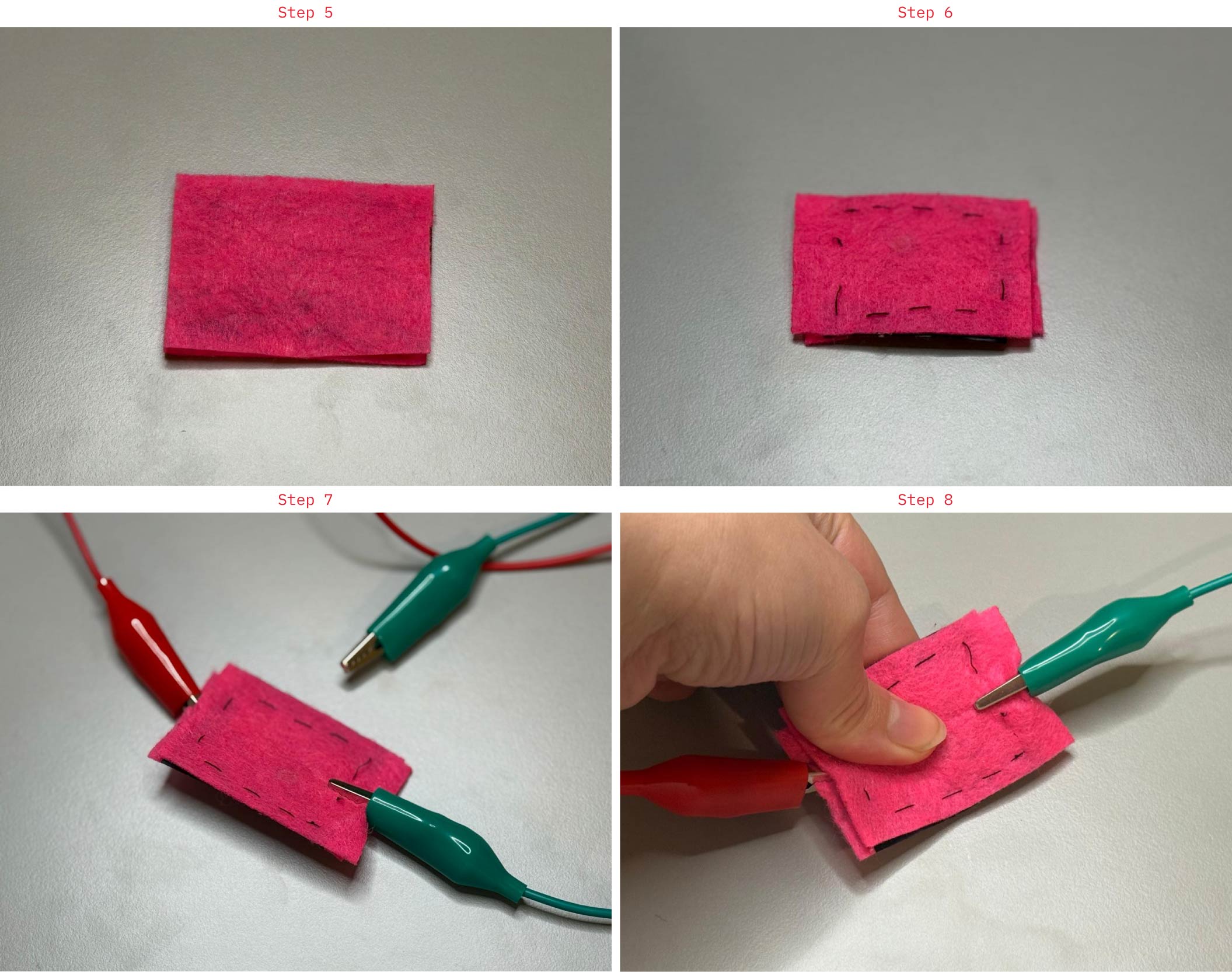
7- Attach connections:
Connect wires (crocodile clips) to: Bottom conductive layer and Top conductive layer.
8- Test the sensor:
No pressure → high resistance → low signal
With pressure → resistance decreases → higher signal
Arduino Code
int sensorValue;

void setup() {
  pinMode(9, OUTPUT);
  Serial.begin(9600);
}

void loop() {
  sensorValue = analogRead(A0);
  Serial.println(sensorValue);

  if (sensorValue > 500) {  // try 300–700
    digitalWrite(9, HIGH);
  } else {
    digitalWrite(9, LOW);
  }

  delay(50);
}
Result
V. Assignment Workflow
A. Ideation
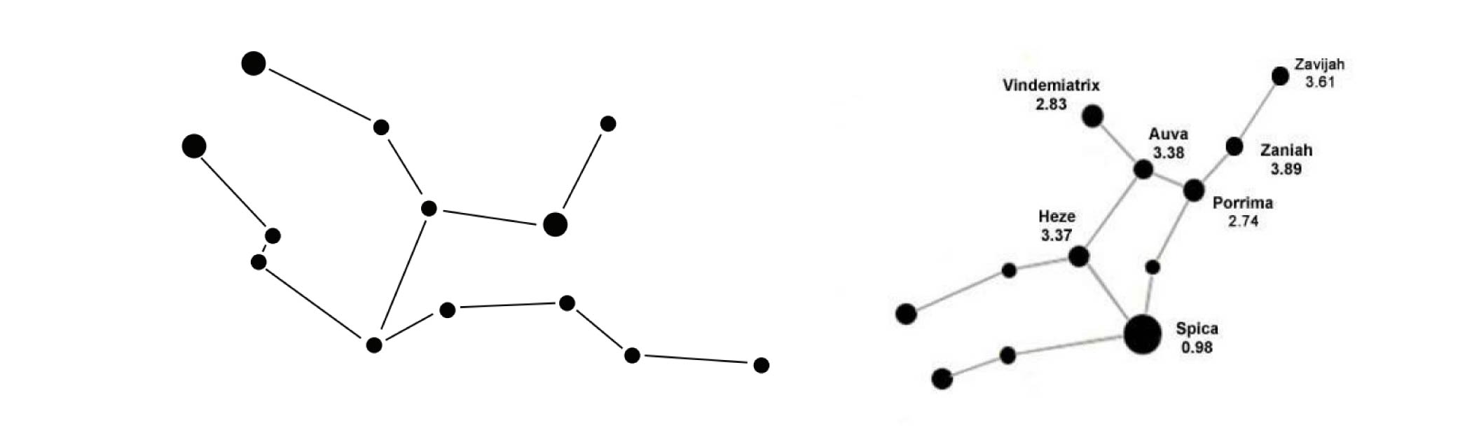
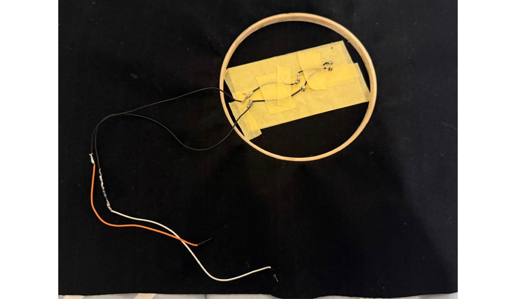
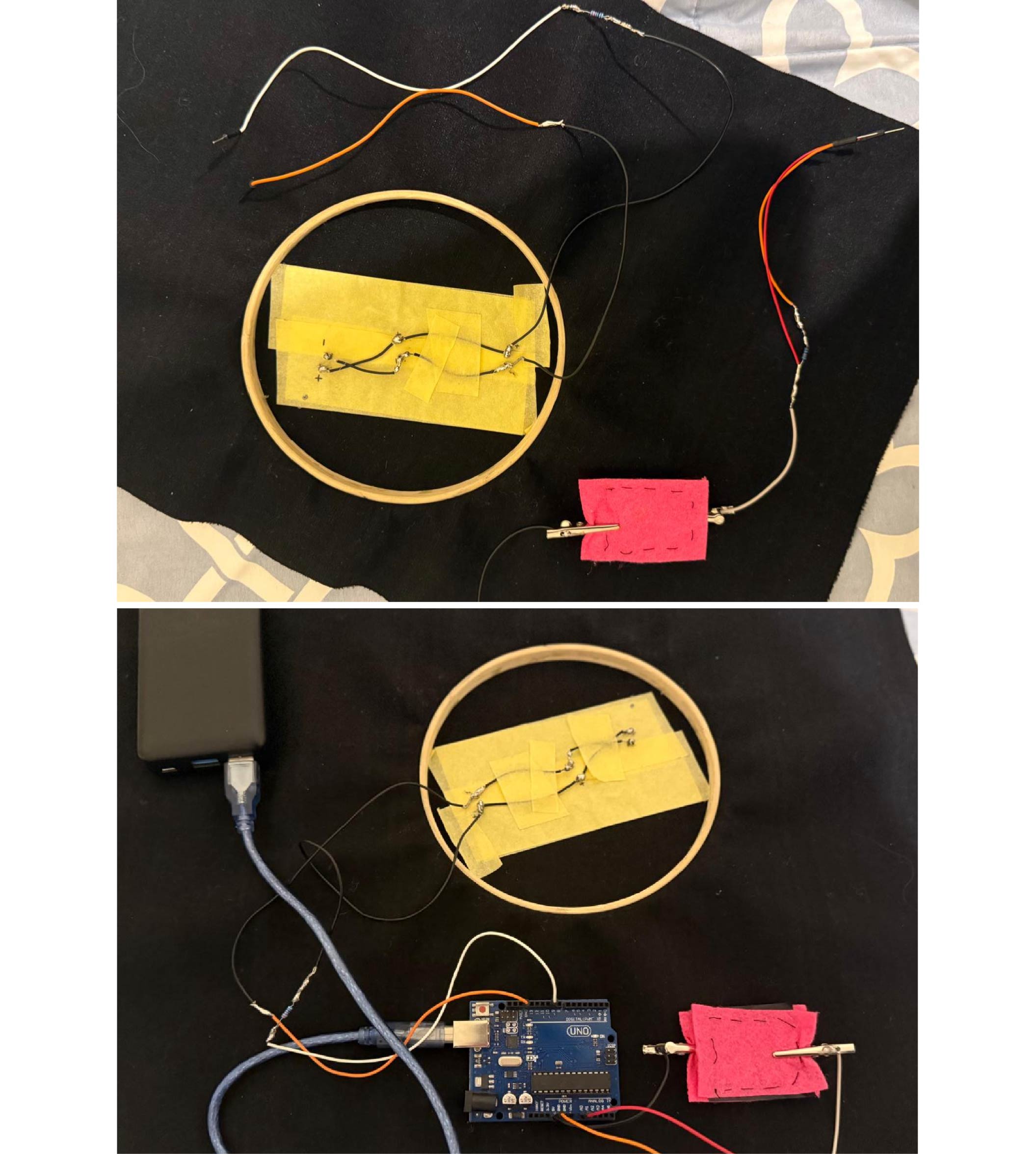
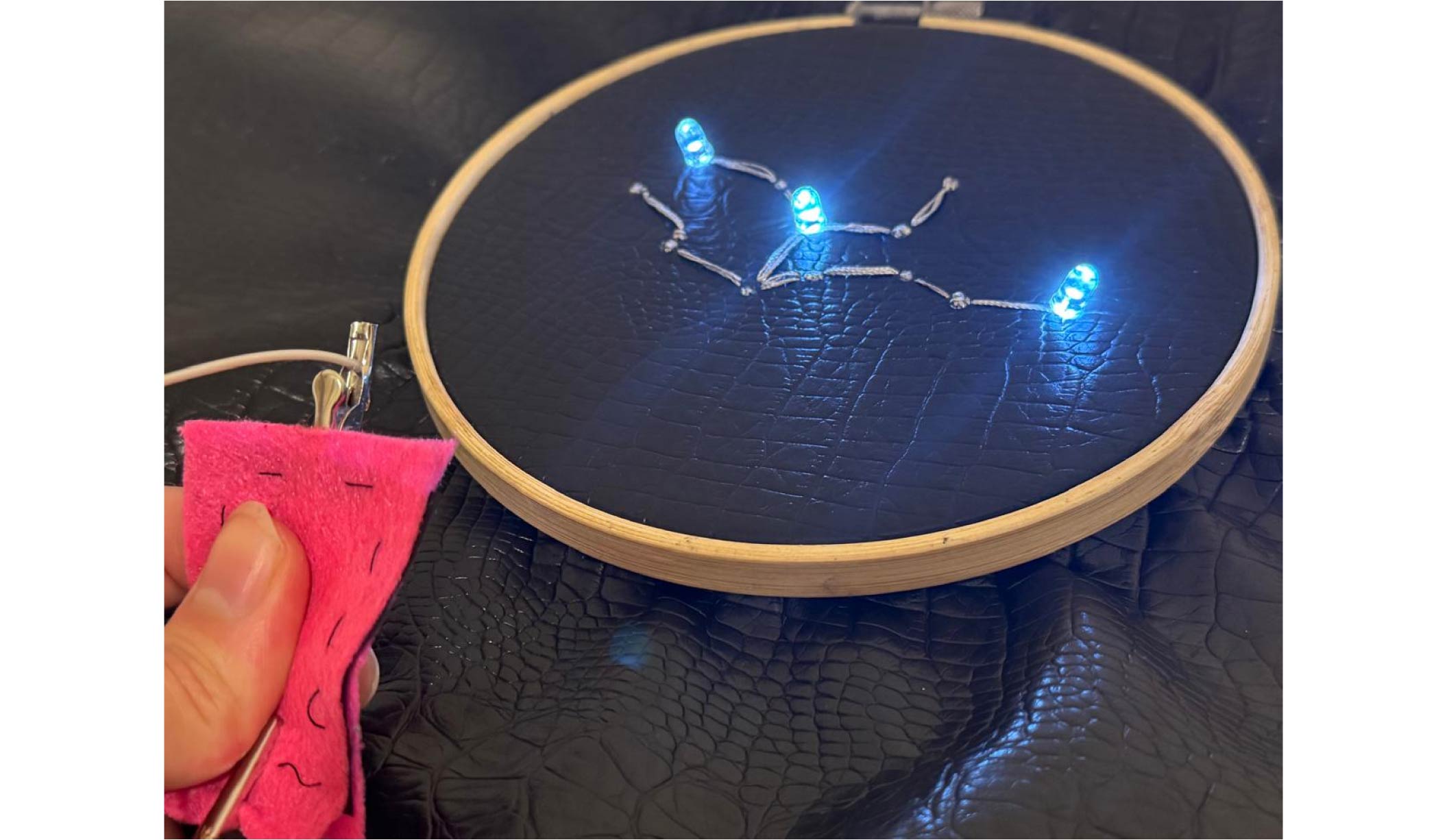
For this assignment, I set out to create something that felt like magic, drawing inspiration from the sky and stars, and my husband’s love for astronomy. I chose the Virgo constellation —his sign— and brought it to life by illuminating its points with LEDs, exploring both analog and digital control.
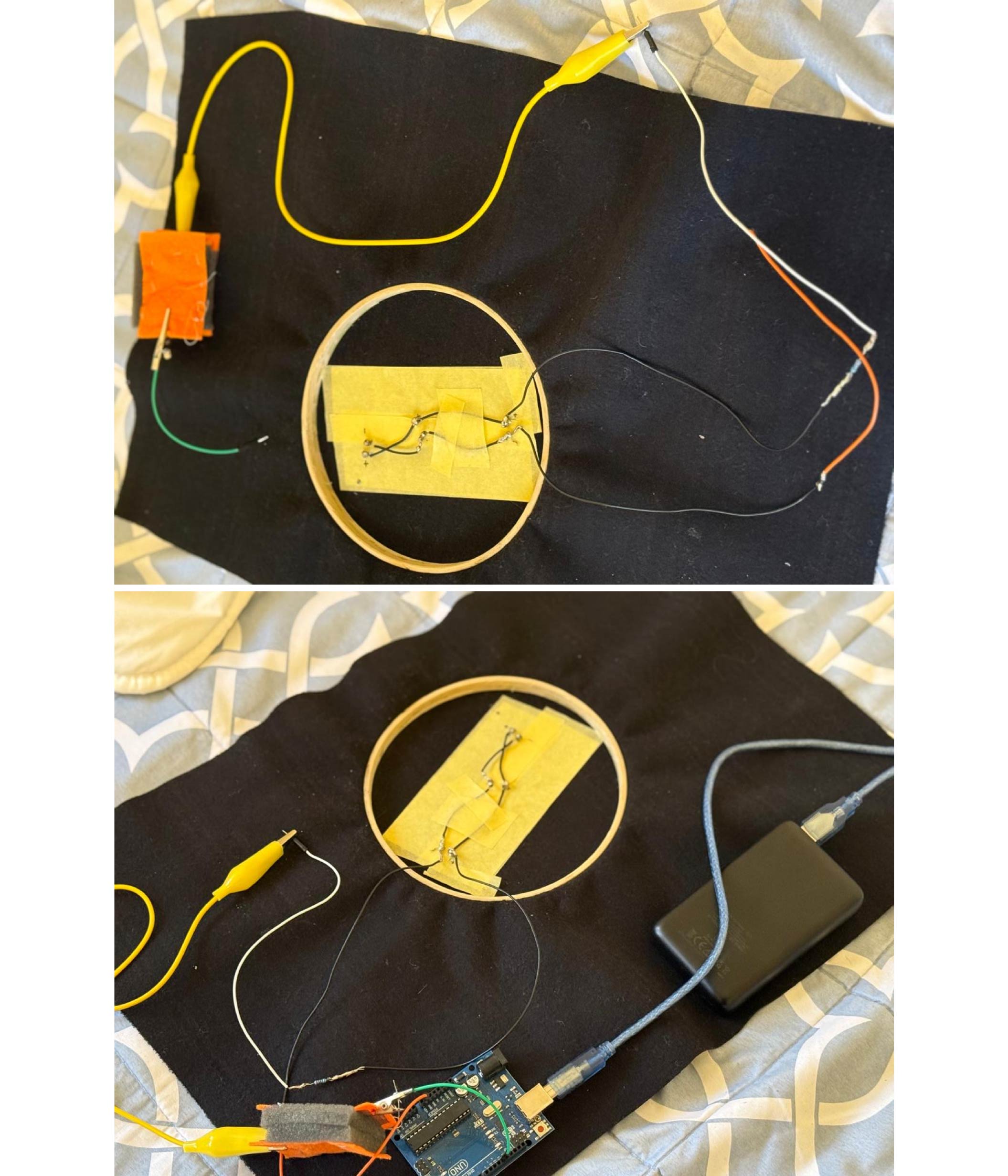
B. Process
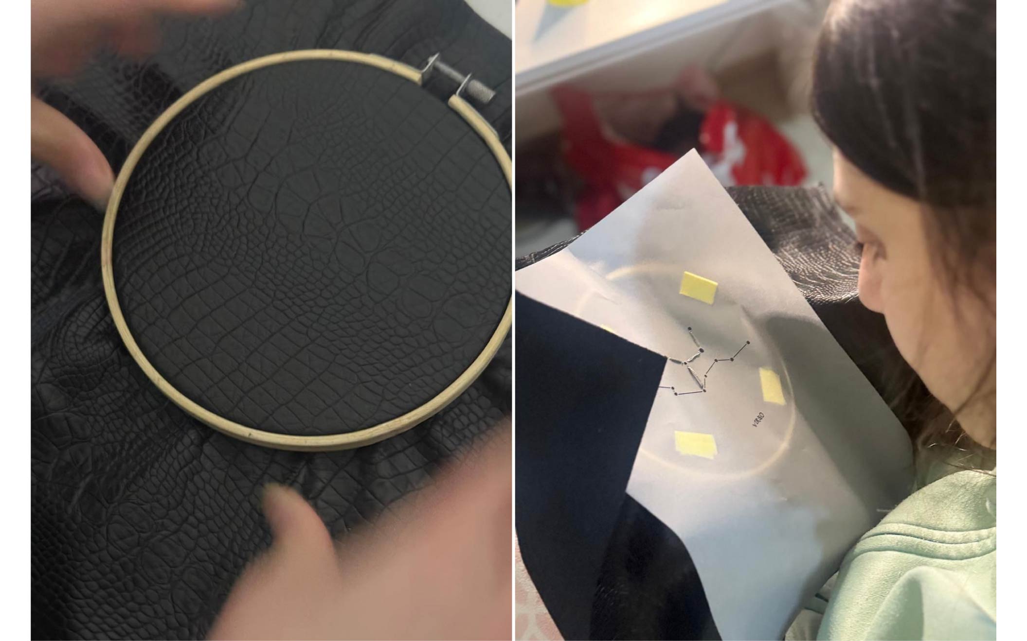
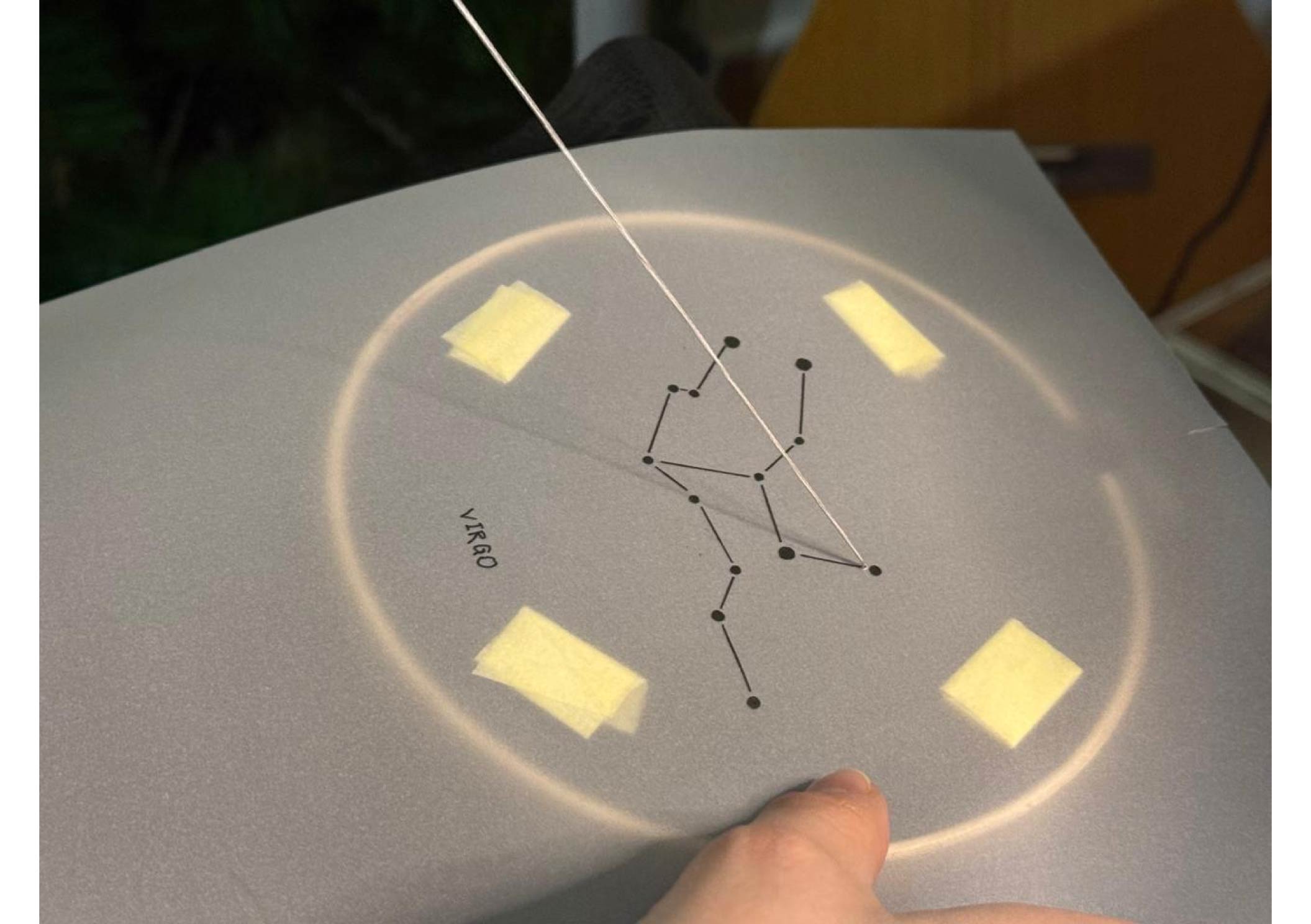
Step 1: Stitching the Constellation.
Step 2: Test leds position.
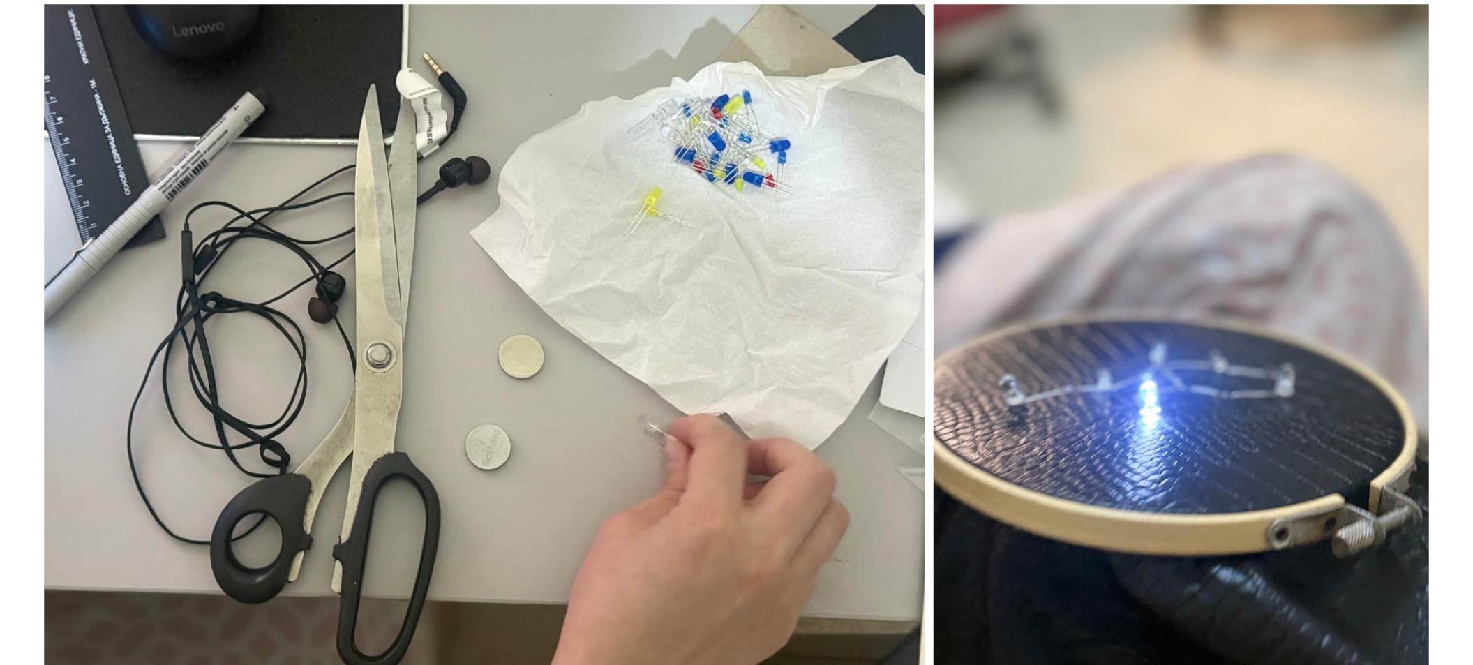
Step 3: Position the LEDs to be connected in a parallel configuration.
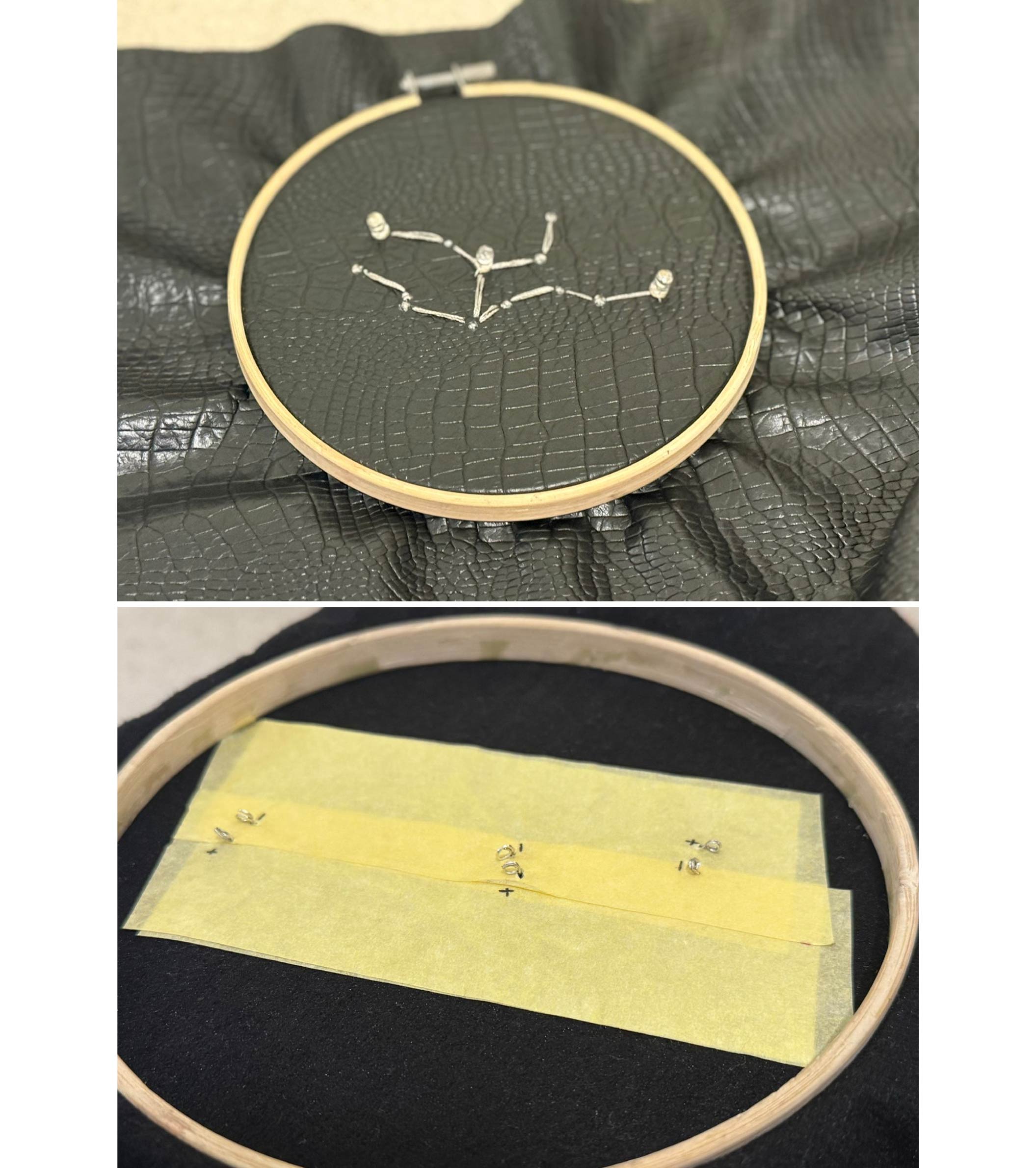
Step 4: Build traces between the all anodes, and then between all cathodes of the 3 leds and solder where needed (as the circuit below).
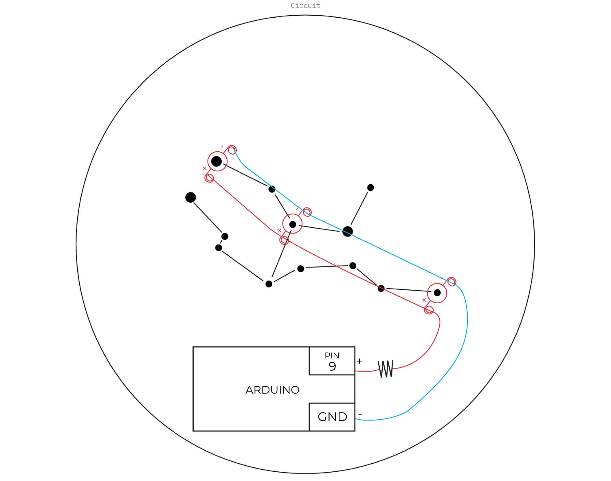
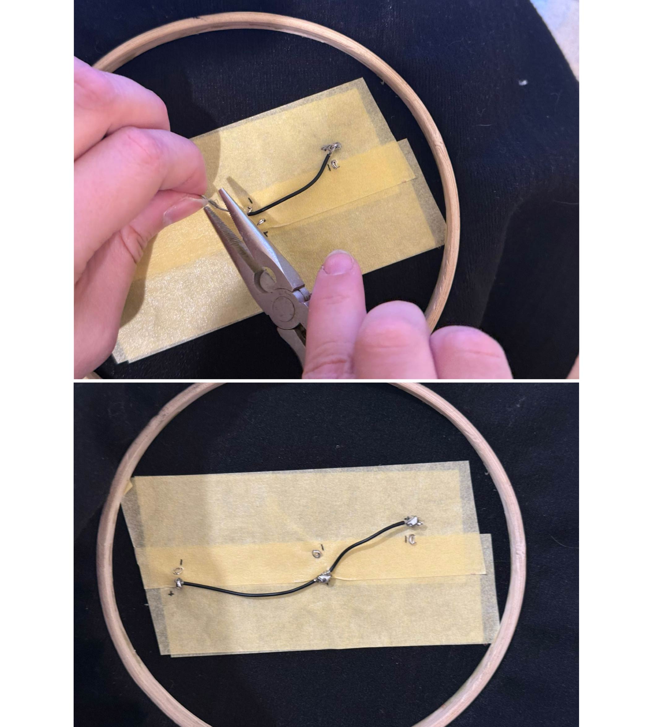
Step 5: Continue traces and connect the anode to a 220 ohm resistor.
C. Control with Digital Switch
Connect the circuit as follows:
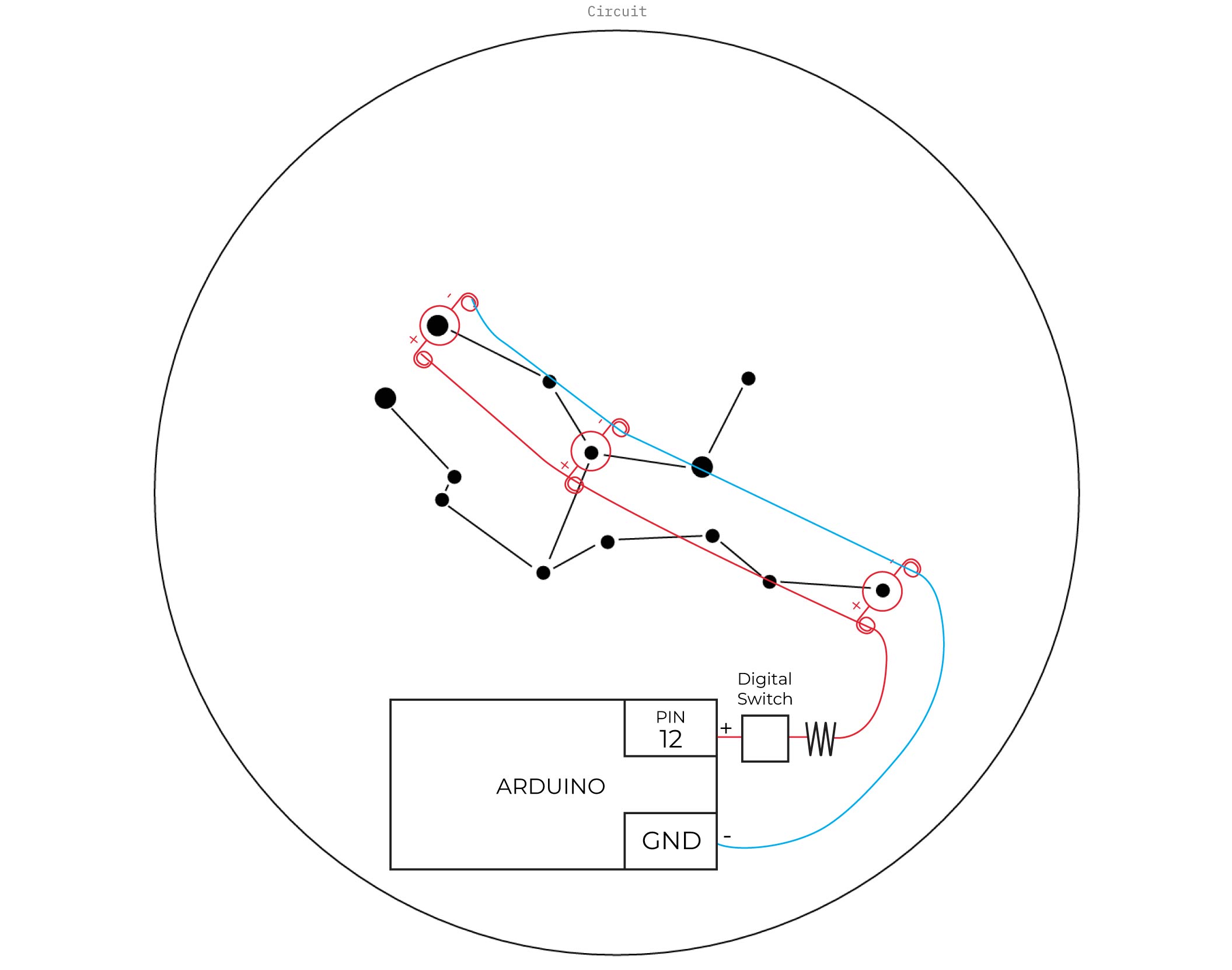
Arduino Code
void setup() {
  // initialize digital pin LED_BUILTIN as an output.
  pinMode(12, OUTPUT);
}

// the loop function runs over and over again forever
void loop() {
  digitalWrite(12, HIGH);  // turn the LED on (HIGH is the voltage level)
  delay(200);                      // wait for a second
  digitalWrite(12, LOW);   // turn the LED off by making the voltage LOW
  delay(200);                      // wait for a second
}
Result
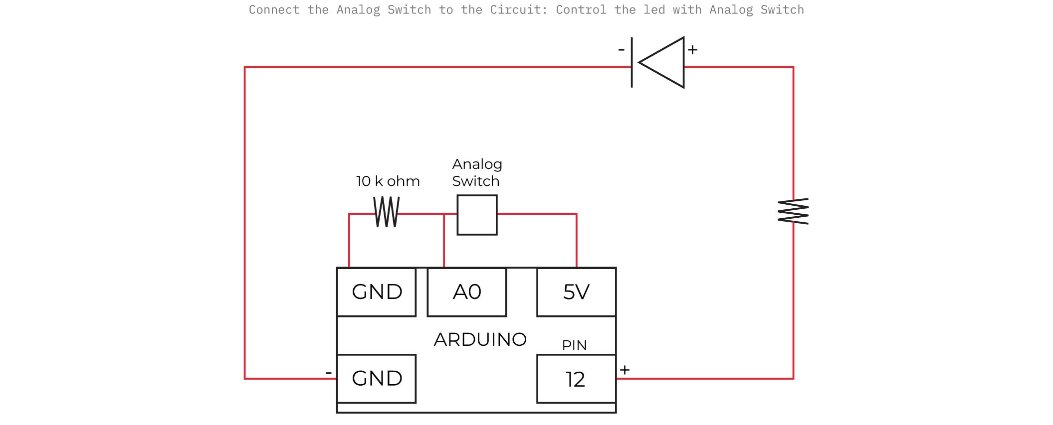
D. Control with Analog Switch
Connect the circuit as follows:
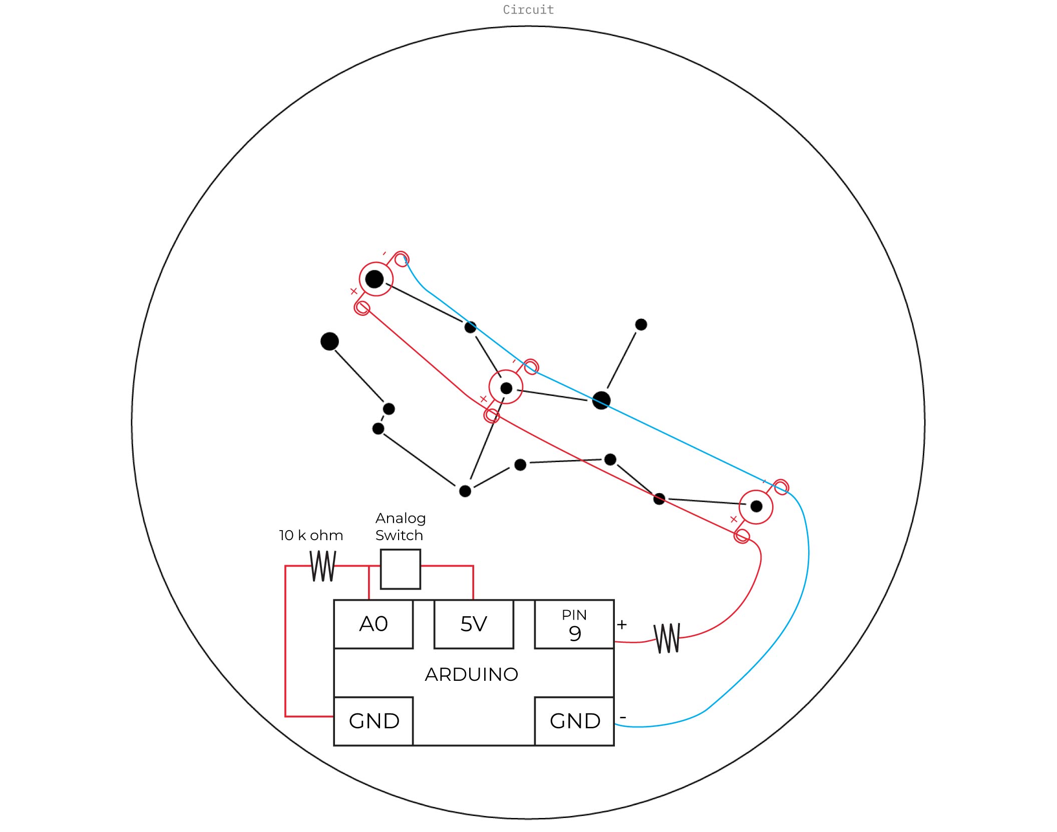
Arduino Code:
int sensorValue;

void setup() {
  pinMode(9, OUTPUT);
  Serial.begin(9600);
}

void loop() {
  sensorValue = analogRead(A0);
  Serial.println(sensorValue);

  if (sensorValue > 500) {  // try 300–700
    digitalWrite(9, HIGH);
  } else {
    digitalWrite(9, LOW);
  }

  delay(50);
}
Result
VI. Fabrication files
-
File: Virgo Constellation ↩