12. Skin Electronics
I. References & Inspiration
II. Intro
Catching the last breaths of this journey and officially closing the first chapter of Fabricademy with this week, where the skin itself becomes the input. So, what are skin electronics? They are soft, wearable circuits designed to adhere directly to the skin, enabling the body to be monitored or interacted with without rigidity or discomfort.
A. Introduction to some new sensors
- Film Pressure sensor is a Force Sensitive Resistors (FSR), it allows you to detect physical pressure, squeezing and weight.
 - Pulse Heart Rate Sensor is designed to accurately measure heart rate by detecting pulse wave signals from the skin. It operates between 3.3V and 5V, making it compatible with most Arduino and other development boards. The sensor consumes minimal power at just 4mA, and it features an analog output for straightforward signal processing.
Remember!
Most common analog sensors are variable resistors, such as potentiometers, light sensors, temperature sensors, and pressure sensors.
When we interact with a variable resistor (changing light levels, rotating a knob, applying pressure, etc.), its resistance value changes and creates an analog signal.
Testing the Pulse Heart Rate Sensor using 128x64 OLED 0.96 inch Display Module (4-pin) (White):
Remember!
Download the SSD1306 library
Code:
#include <Wire.h>
#include <Adafruit_GFX.h>
#include <Adafruit_SSD1306.h>
#define SCREEN_WIDTH 128 // OLED display width, in pixels
#define SCREEN_HEIGHT 32 // OLED display height, in pixels
#define OLED_RESET 4
Adafruit_SSD1306 display(SCREEN_WIDTH, SCREEN_HEIGHT, &Wire, OLED_RESET);

int x=0;
int lastx=0;
int lasty=0;
int LastTime=0;
int ThisTime;
bool BPMTiming=false;
bool BeatComplete=false;
int BPM=0;
#define UpperThreshold 560
#define LowerThreshold 530

void setup() {
  display.begin(SSD1306_SWITCHCAPVCC, 0x3C);
  display.clearDisplay();
  display.setTextSize(1);
}


void loop()
{
  if(x>127)
  {
    display.clearDisplay();
    x=0;
    lastx=x;
  }

  ThisTime=millis();
  int value=analogRead(0);
  display.setTextColor(WHITE);
  int y=60-(value/16);
  display.writeLine(lastx,lasty,x,y,WHITE);
  lasty=y;
  lastx=x;

  // calc bpm
  if(value>UpperThreshold)
  {
    if(BeatComplete)
    {
      BPM=ThisTime-LastTime;
      BPM=int(60/(float(BPM)/1000));
      BPMTiming=false;
      BeatComplete=false;
    }
    if(BPMTiming==false)
    {
      LastTime=millis();
      BPMTiming=true;
    }
  }
  if((value<LowerThreshold)&(BPMTiming))
    BeatComplete=true;

    // display bpm
  display.fillRect(0,0,128,8,BLACK);
  display.setCursor(0,0);
  display.print(BPM);
  display.print(" BPM");
  display.display();
  x++;
}
III. Class Experimentation
Building up some sensors with Emma!
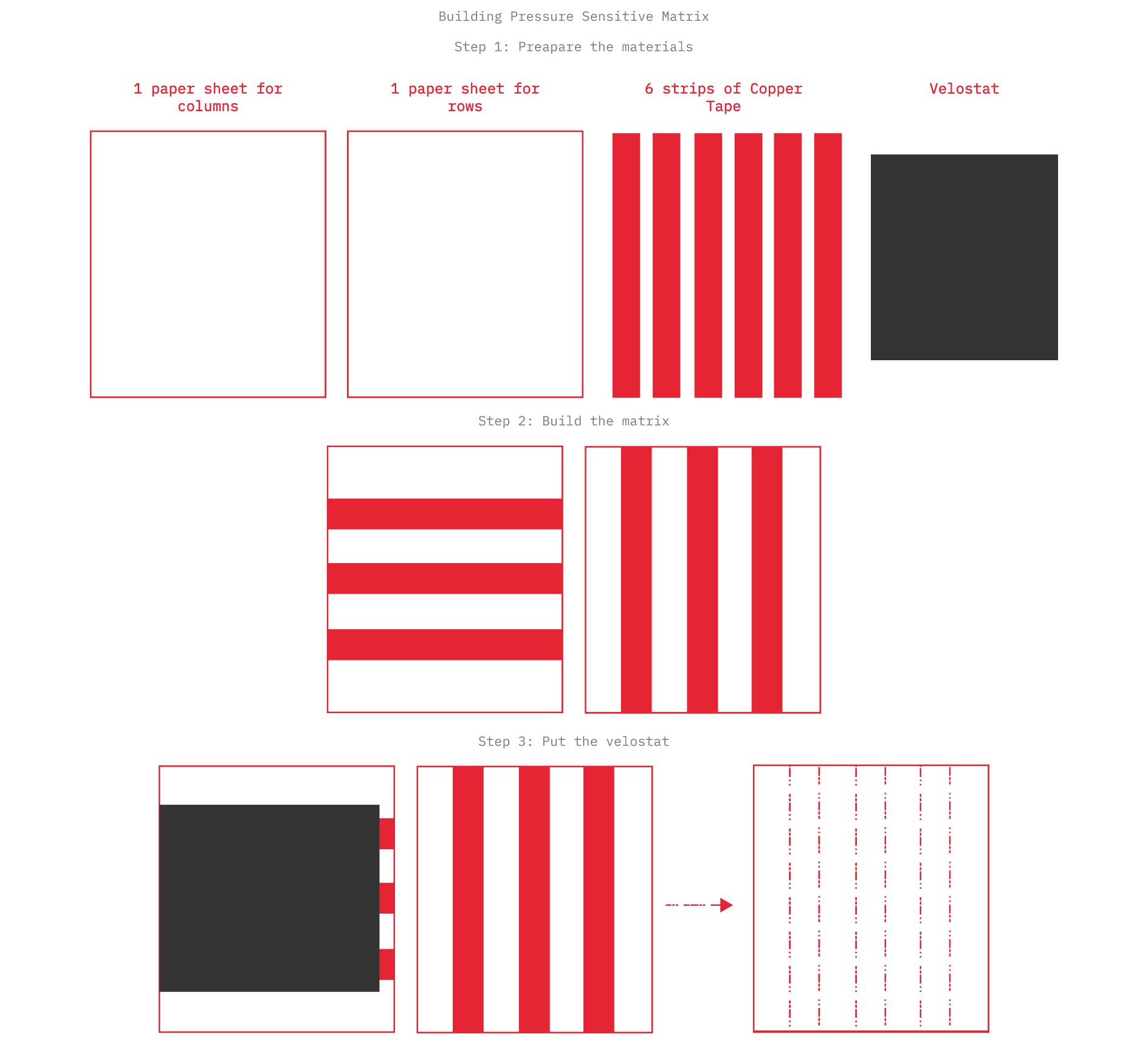
Pressure Sensor (Pressure Sensitive Matrix)
Initially we have to differ between two terms a Pressor Sensor which is a device that measures force applied on a surface. It tells you how much pressure, not necessarily where unless it is arranged in a matrix, and Sensitive Matrix (also called a sensing matrix or sensor array) which is a grid of multiple sensing points forming a pattern of many sensors arranged in rows and columns, giving you spatial information (where you touched + how much).
Notice!
-
A pressure-sensitive matrix is a matrix made from many tiny pressure sensors.
-
A pressure sensor by itself is just one point.
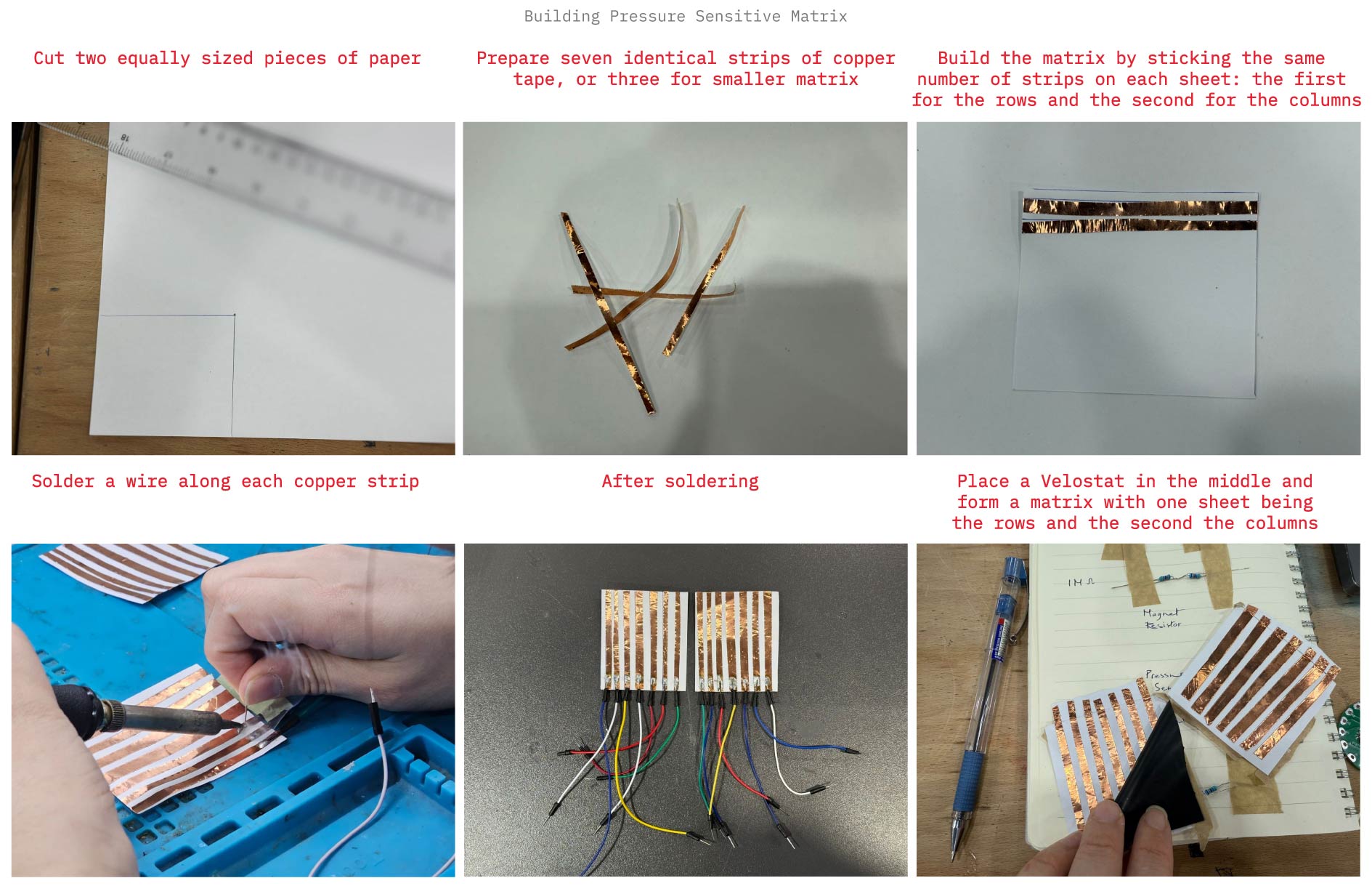
A. Building Process
Process
 Application
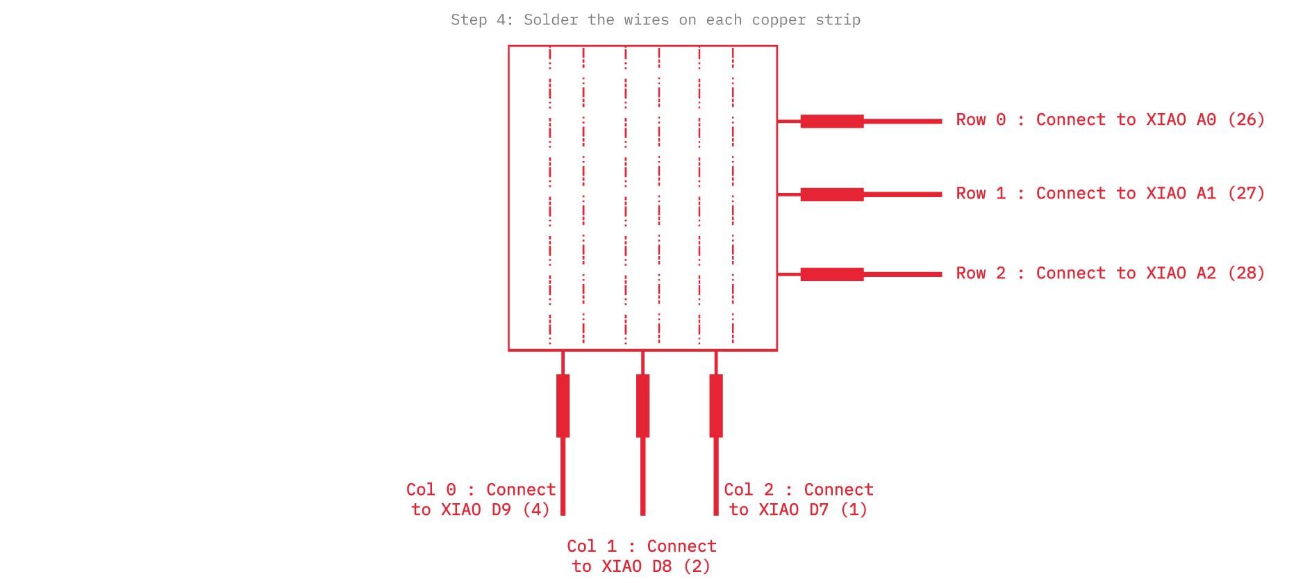
Note: During the application process, we mistakenly planned for 7 strips on each side instead of 3, however, we continued with 3 per side since the wiring had already been completed accordingly. (wiring 3 strips from each side)

B. Arduino IDE Code
int row0 = A0;  //first row pin
int row1 = A1;  //second row pin
int row2 = 2;  //third row pin

int col0 = D9;    //first column pin
int col1 = D8;    //second column pin
int col2 = D7;    //third column pin


int incomingValue0 = 0; //variable to save the sensor reading
int incomingValue1 = 0; //variable to save the sensor reading
int incomingValue2 = 0; //variable to save the sensor reading

int incomingValue3 = 0; //variable to save the sensor reading
int incomingValue4 = 0; //variable to save the sensor reading
int incomingValue5 = 0; //variable to save the sensor reading

int incomingValue6 = 0; //variable to save the sensor reading
int incomingValue7 = 0; //variable to save the sensor reading
int incomingValue8 = 0; //variable to save the sensor reading

void setup() {

  // set all rows to INPUT (high impedance):
    pinMode(row0, INPUT_PULLUP);
    pinMode(row1, INPUT_PULLUP);
    pinMode(row2, INPUT_PULLUP);

 //set the firt column as output
  pinMode(col0, OUTPUT);
  pinMode(col1, OUTPUT);
  pinMode(col2, OUTPUT);


  //open serial communication
  Serial.begin(9600);

}

void loop() {

  // FIRST BLOCK OF READINGS----------------------------
  //set the col0 to low (GND)
  digitalWrite(col0, LOW);
  digitalWrite(col1, HIGH);
  digitalWrite(col2, HIGH);

  //read the three rows pins
    incomingValue0 = analogRead(row0);
    incomingValue1 = analogRead(row1);
    incomingValue2 = analogRead(row2);
  // --------------------------------------------------

  //set the col1 to low (GND)
  digitalWrite(col0, HIGH);
  digitalWrite(col1, LOW);
  digitalWrite(col2, HIGH);

    incomingValue3 = analogRead(row0);
    incomingValue4 = analogRead(row1);
    incomingValue5 = analogRead(row2);

  //set the col2 to low (GND)
  digitalWrite(col0, HIGH);
  digitalWrite(col1, HIGH);
  digitalWrite(col2, LOW);

    incomingValue6 = analogRead(row0);
    incomingValue7 = analogRead(row1);
    incomingValue8 = analogRead(row2);

  // Print the incoming values of the grid:

    Serial.print(incomingValue0);
    Serial.print("\t");
    Serial.print(incomingValue1);
    Serial.print("\t");
    Serial.print(incomingValue2);
    Serial.print("\t");
    Serial.print(incomingValue3);
    Serial.print("\t");
    Serial.print(incomingValue4);
    Serial.print("\t");
    Serial.print(incomingValue5);
    Serial.print("\t");
    Serial.print(incomingValue6);
    Serial.print("\t");
    Serial.print(incomingValue7);
    Serial.print("\t");
    Serial.println(incomingValue8);

delay(100); //wait millisecond
}
Result:
C. Processing Code and Measures
/*
The sensors values are not calibrated.

*/

/*
Code based on Tom Igoe’s Serial Graphing Sketch
>> http://wiki.processing.org/w/Tom_Igoe_Interview
Reads X analog inputs and visualizes them by drawing a grid
using grayscale shading of each square to represent sensor value.
>> http://howtogetwhatyouwant.at/
*/

import processing.serial.*;

Serial myPort; // The serial port
int rows = 3;
int cols = 3;
int maxNumberOfSensors = rows*cols;
float[] sensorValue = new float[maxNumberOfSensors]; // global variable for storing mapped sensor values
float[] previousValue = new float[maxNumberOfSensors]; // array of previous values
int rectSizeX = 0;
int rectSizeY = 0;
int rectY;


void setup () {
  size(1000, 1000); // set up the window to whatever size you want
  rectSizeX = width/rows;
  rectSizeY = height/cols;


  println(Serial.list()); // List all the available serial ports
  String portName = Serial.list()[1]; // set the number of your serial port!
  myPort = new Serial(this, portName, 9600);
  myPort.clear();
  myPort.bufferUntil('\n'); // don’t generate a serialEvent() until you get a newline (\n) byte
  background(255); // set inital background
  smooth(); // turn on antialiasing
  rectMode(CORNER);
}

void draw () {
  for (int i = 0; i < maxNumberOfSensors; i++) {
    fill(sensorValue[i]);
    rect(rectSizeX * (i%rows), rectY, rectSizeX, rectSizeY); //top left
    if((i+1) % rows == 0) {
      rectY += rectSizeX;
    }
  }
  rectY=0;
}


void serialEvent (Serial myPort) {
  String inString = myPort.readStringUntil('\n'); // get the ASCII string
  if (inString != null) { // if it’s not empty
    inString = trim(inString); // trim off any whitespace
    int incomingValues[] = int(split(inString, "\t")); // convert to an array of ints

    if (incomingValues.length <= maxNumberOfSensors && incomingValues.length > 0) {
      for (int i = 0; i < incomingValues.length; i++) {
        // map the incoming values (0 to 1023) to an appropriate gray-scale range (0-255):
        sensorValue[i] = map(incomingValues[i], 000, 900, 0, 255); // stretch 5×5
        sensorValue[i] = constrain(incomingValues[i], 0, 255);
        //println(sensorValue[i]); // print value to see
        //println(incomingValues[i]);
      }
    }
  }
}
Result:
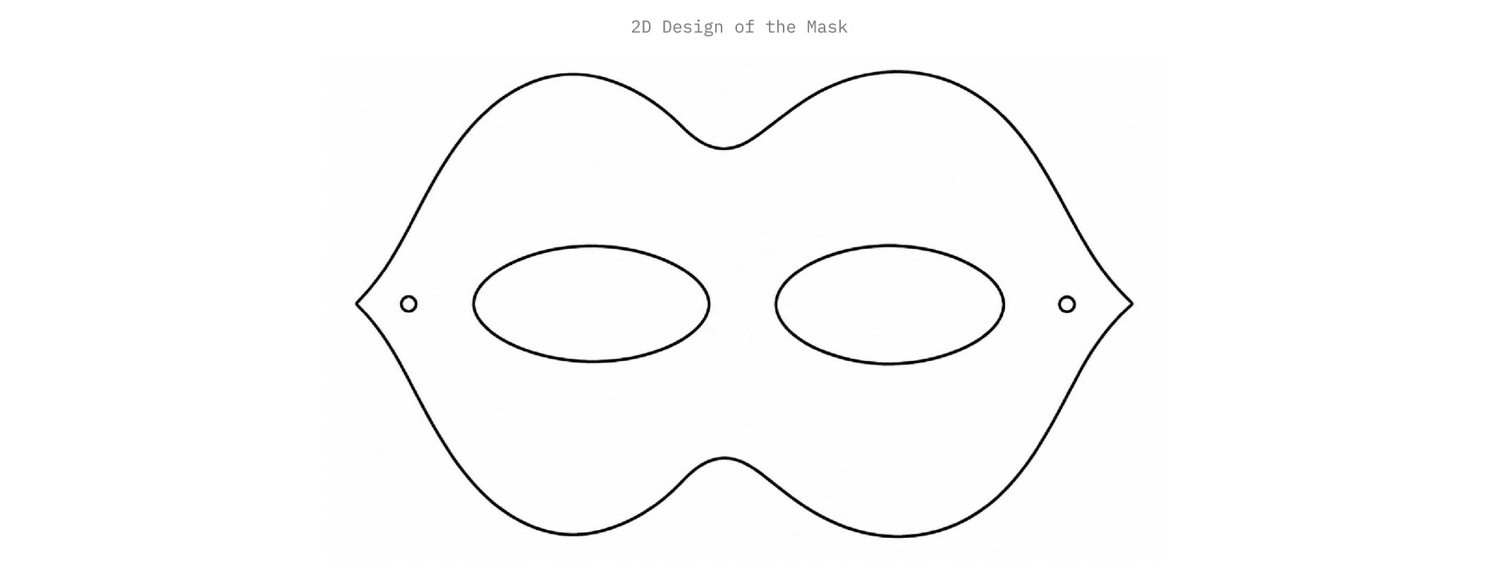
IV. Week Project (Coral Mask)
A. Ideation
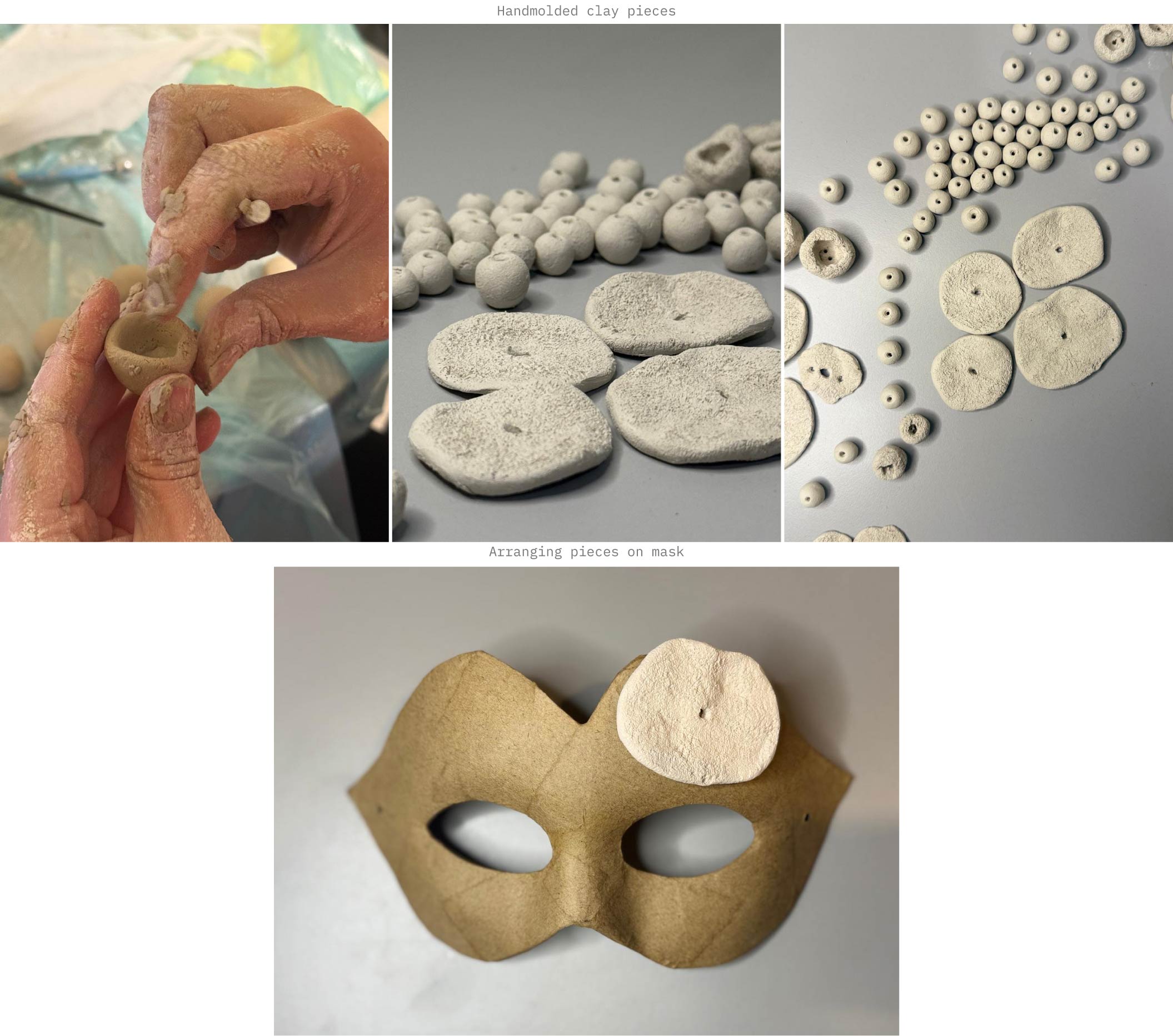
For this week’s assignment, I set out to design a mask using hand-molded clay modules inspired by coral surfaces. I was drawn to creating a mask due to my fascination with 15th-century Venetian Renaissance masquerade balls. My approach was to integrate white LEDs into selected areas of the mask and control them using a FSR42 film pressure sensor.

B. Process
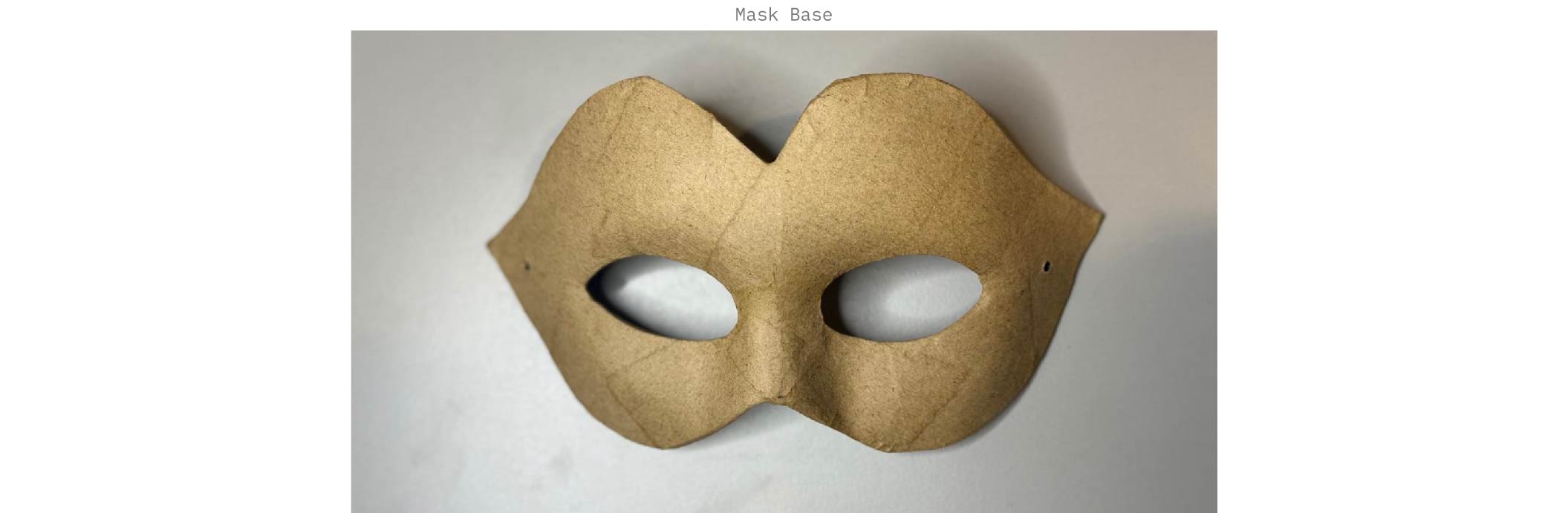
- Mask Base:
My initial intention was to design the mask base, cut it, and mold it onto a face scaffold. However, this step became unnecessary when I found a nearly identical base to my 2D design at a nearby craft store.
Refer to Clay Experimentation for more insight on hand molding the clay pieces.
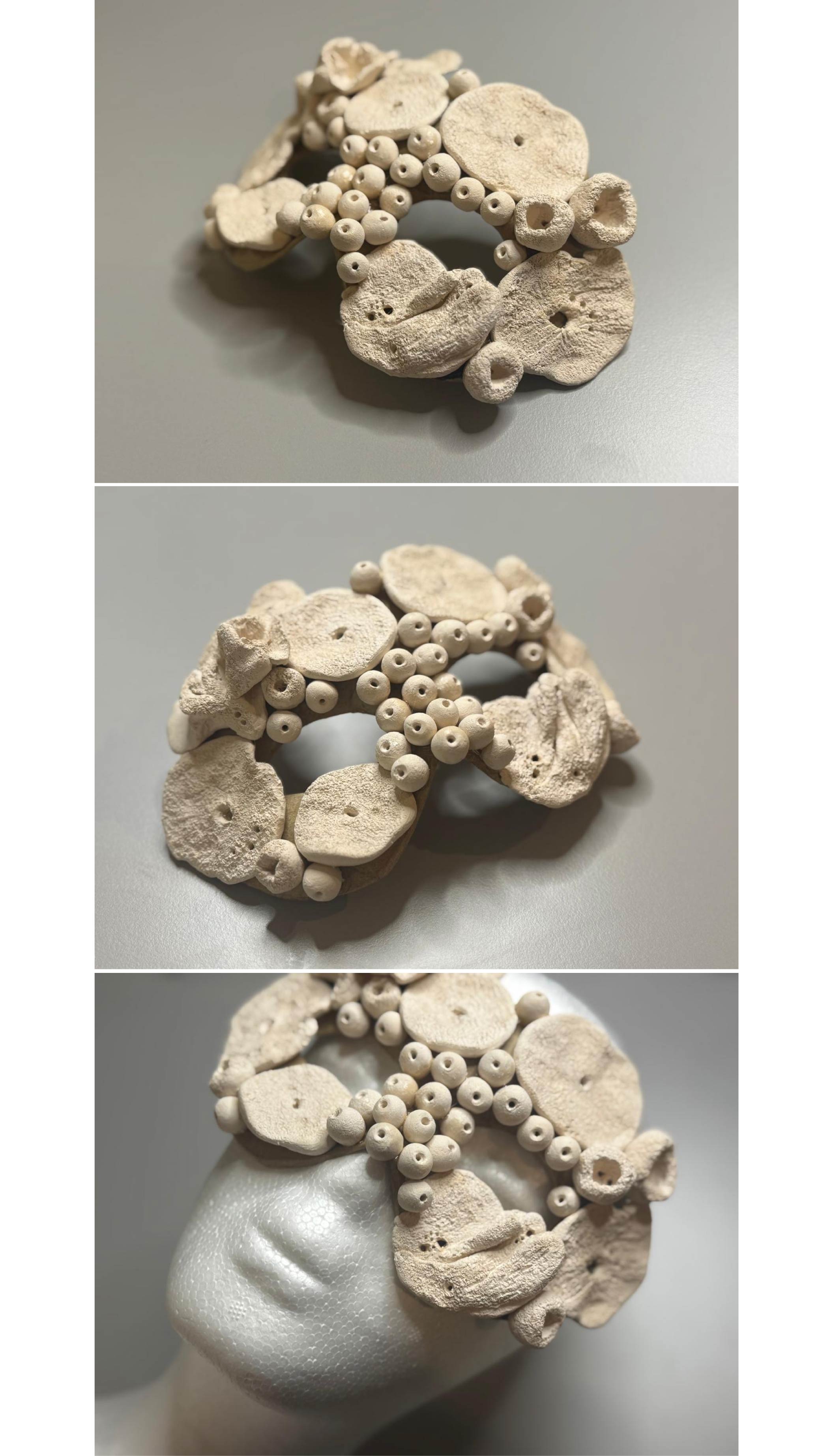
- Mask result prior to LED integration, exploring a surreal and edgy aesthetic:
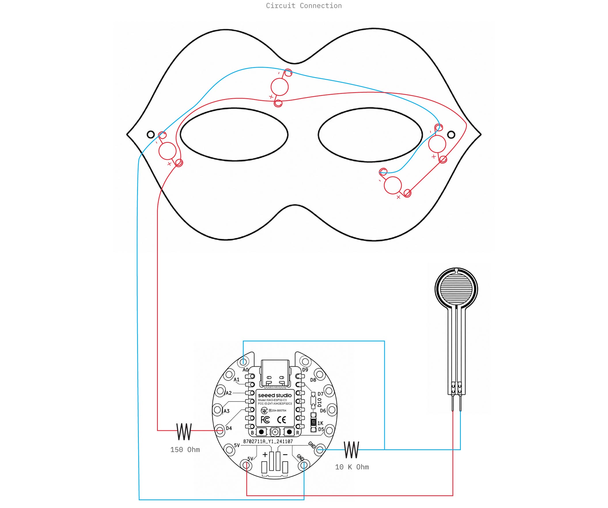
- Electronic assembly and connections:
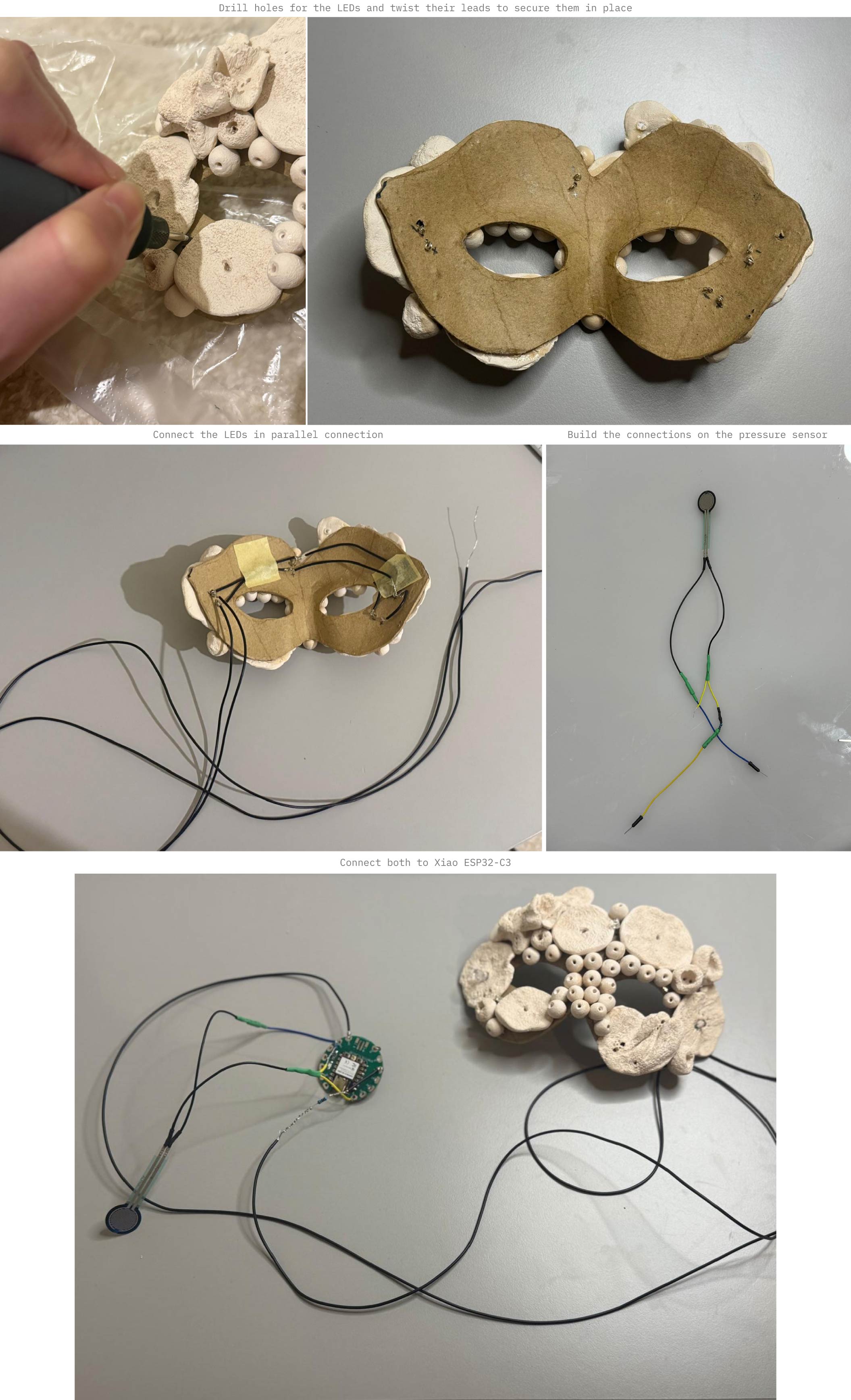
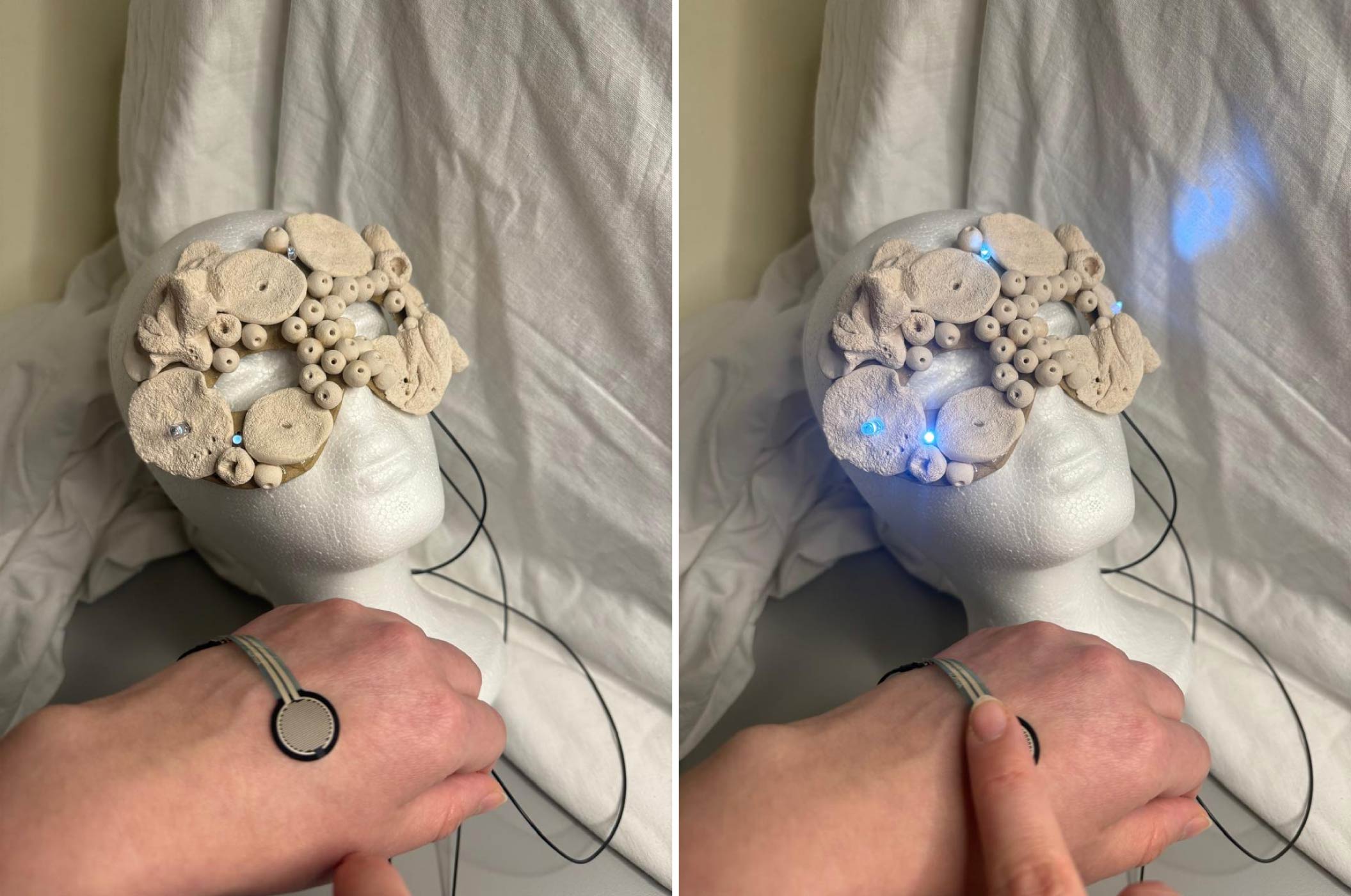
- Testing:
C. Code
#define FSR_PIN D0   // safer naming
#define LED_PIN D4   // use board pin name

void setup() {
  Serial.begin(115200);
}

void loop() {
  int fsrValue = analogRead(FSR_PIN);
  Serial.println(fsrValue);

  int brightness = map(fsrValue, 0, 4095, 0, 255);
  brightness = constrain(brightness, 0, 255);

  analogWrite(D4, brightness);

  delay(20);
}
D. Result
V Fabrication files
-
File: Coral Mask Base ↩