Computational Couture
Work for this Week
References, research & inspiration
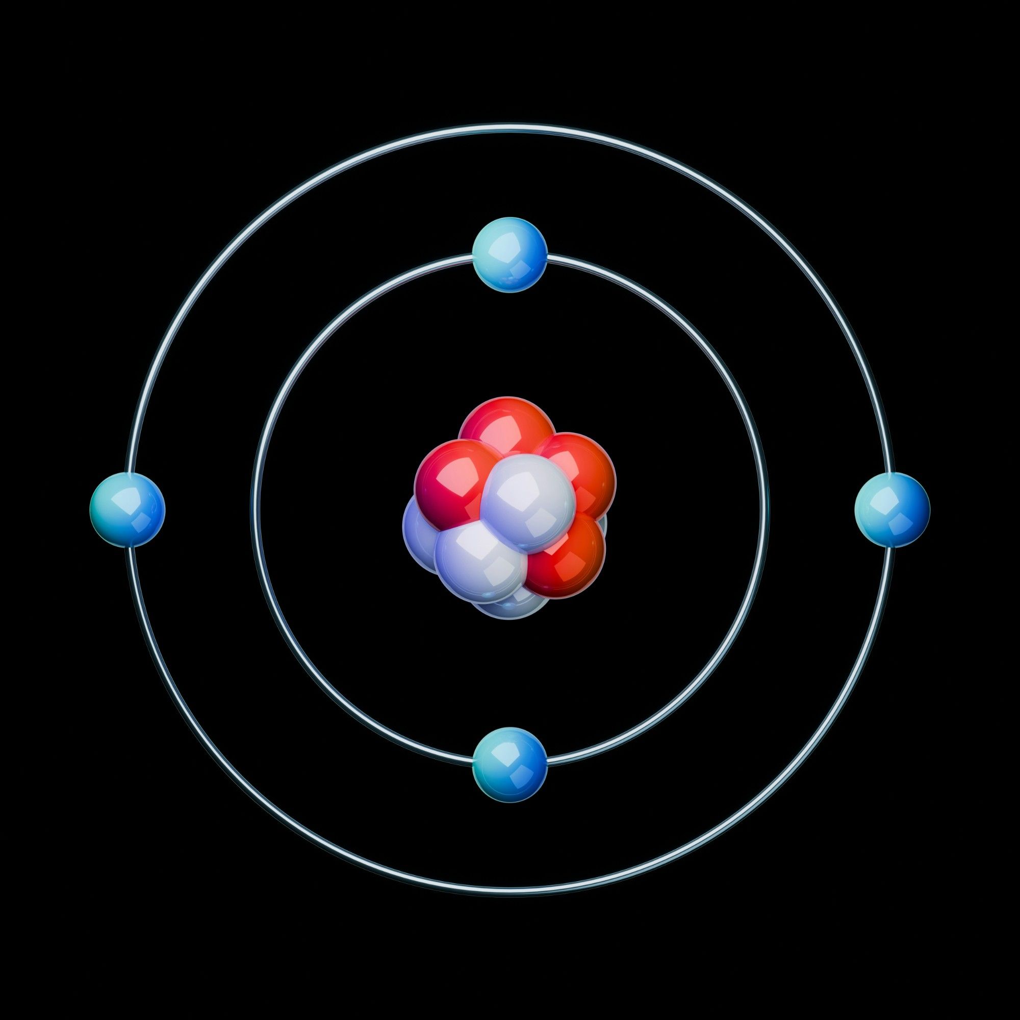
Rico’s recommendation to explore randomness made me interested in the word randomness itself. When I started thinking about it, I realised that randomness is something we see and experience every day, often without paying much attention to it. We see it in the patterns of leaves, the movement of clouds, the shapes of mountains, and even the way lines and shapes appear in abstract art. There is a certain beauty in randomness because not everything needs to be perfectly planned, symmetrical, or predictable to be beautiful. As a student, this word randomness came arross while studying chemistry and learning about the movement of electrons around an atom. I learned that the behaviour of electrons is probabilistic rather than perfectly predictable. Thinking about it now, randomness is not just a scientific concept; it is also part of the world around us.
This idea made me think about how I could connect randomness with this week’s assignment. Instead of focusing only on building a 3D model and printing it, I wanted to experiment with creating random patterns and exploring how they could be printed using a 3D printer.
step 1 Getting the 3D printer from the lab and setting up
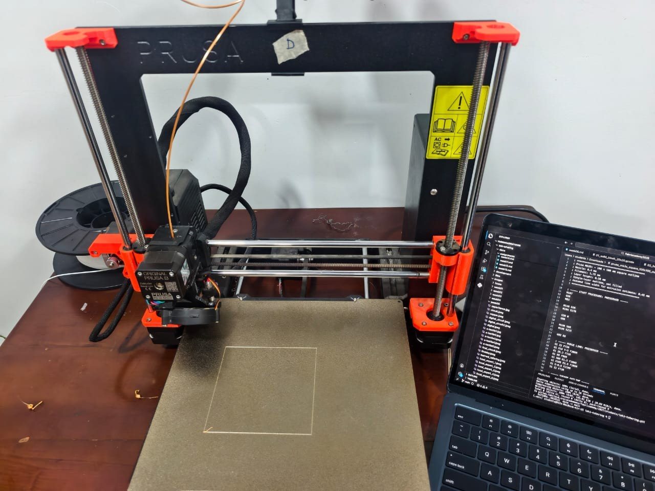
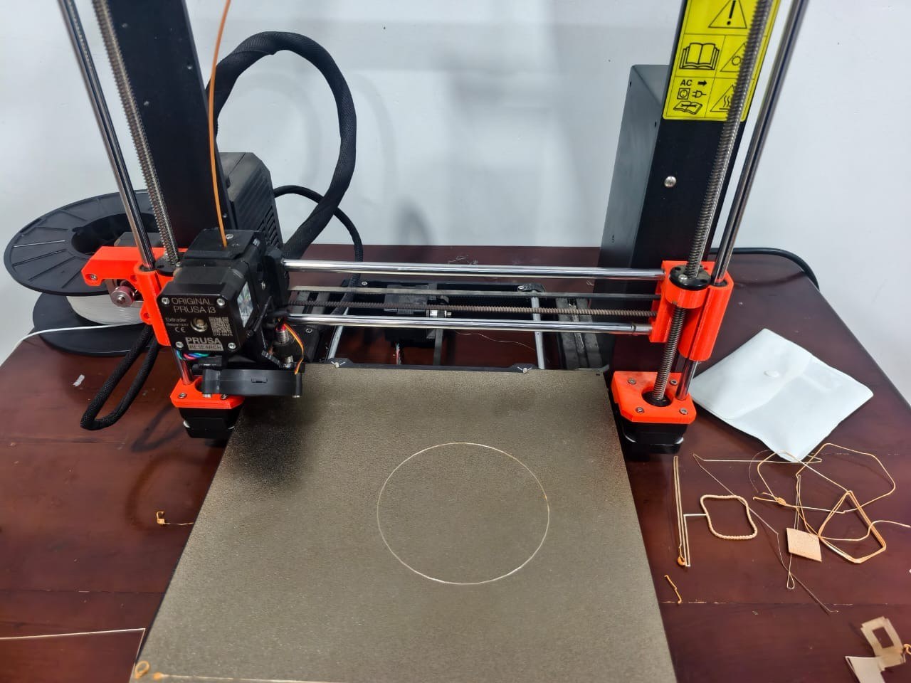
This week is mostly on working the 3d design and 3d printer. my first thought was how to get the 3d printer and get myself ready for the assigment. so i went to fab and ask the anith lab assistant for the lab with the printer. so i brought one 3d printer that is prusa 3d printer mk3s+. before going to any of the design. i try to setup the test wheather the printer is working fine or not. it is not my first experince with the printer. i got chance work wiht printer before. i really dont have to work hard on that luckily.
Step 2. Tyring not to use the slicer to custome generate gcode, instead trying to do deeper into commands. how gcode really works with printer.
After setting up the printer. most intereseting things and experiment the upon the suggestion of rico. to make custom g code, which is fun part of this week, espically making your own gcode without using the slicer, to go bit techbical deep with regarding the 3d printer. esapically the gcode. with my preiovus experince i onluy knew gcode is printer movment, but what i found all the start and end prodecure is commended instead the gcode like bed heat and nozzle heat and extrusion which make more surprise to me. Gocode is the geometric code, e it is lanagage where computaional machine understand like 3d printer and cnc undstand. we design any model in any3d software, we bring the stl(standard trigular lanaguege) and we use slicer liek pursa slicer to slice the model and convert into gcode to print. but this time, i tried to write small gocde to print small shape like squre. mainly to undstand the commands of the gcode like g0 etc. List importnat comamnds. what i found is thatm there is small difference between the cutom gcode you make and slicer. both has advantges and distanages on my thought, you have full control on the cutom gcode, but you also need to do more experiment, where is slicer is make work faster but it is also rigid, dont allowed to control the parts of printer espically if your printing the complex shape.
List of commands of gcode
Step 3. using the ptjs to generate randomness of pattern
Process and Workflow
Step 1: Getting the 3D Printer from the Lab and Setting It Up
This week was mainly focused on 3D design and 3D printing. My first thought was to get a 3D printer and prepare myself for the assignment. So, I went to the FabLab and asked Anith, the lab assistant, for help getting a printer. I brought a Prusa i3 MK3S+ back to my workspace.
Before starting any design work, I wanted to make sure that the printer was working properly. I set it up and tested the homing procedure to check whether everything was functioning as expected. Luckily, this was not my first experience with a 3D printer. I had worked with one before, so I did not have to struggle much with the initial setup. This allowed me to move on to the more interesting part of the assignment: understanding the printer and experimenting with my own G-code.

Step 2. Exploring Custom G-code Instead of Using a Slicer
After setting up the printer, I started exploring one of the most interesting parts of this week's assignment: generating my own custom G-code without relying on a slicer. This was also based on Rico's suggestion to go deeper into the technical side of 3D printing and understand how the printer actually works.
Before this experiment, I knew that G-code was responsible for controlling the movement of a 3D printer, but I had never really explored it in detail. What surprised me was that the entire printing procedure involves many different commands, not just instructions for moving the nozzle. Commands can also control things such as nozzle temperature, bed temperature, filament extrusion, fan speed, and other printer operations.
I began to understand that G-code is a language used to give instructions to machines such as 3D printers and CNC machines. Normally, we design a model using 3D modelling software, export it as an STL file (STL is commonly understood as Standard Tessellation Language), and import it into a slicer such as PrusaSlicer. The slicer divides the model into layers and generates the G-code needed to print it.
However, this time, I wanted to understand what happens behind that process. Instead of allowing the slicer to generate all the instructions, I started writing small pieces of G-code myself. I began with a simple square so that I could focus on understanding the commands rather than worrying about a complicated design.
Some of the important commands I explored were:
| G-code command | What I learned |
|---|---|
G0 |
Moves the printer without a printing extrusion move, typically used for positioning. |
G1 |
Controls linear movement and can include filament extrusion. |
G28 |
Homes the printer's axes. |
G90 |
Sets positioning to absolute coordinates. |
G91 |
Sets positioning to relative coordinates. |
M82 |
Sets the extruder to absolute extrusion mode. |
M83 |
Sets the extruder to relative extrusion mode. |
M104 |
Sets the nozzle temperature without waiting for it to reach the target. |
M109 |
Sets the nozzle temperature and waits for it to reach the target. |
M140 |
Sets the heated-bed temperature without waiting. |
M190 |
Sets the heated-bed temperature and waits for it to reach the target. |
M106 |
Controls the part-cooling fan. |
M107 |
Turns the part-cooling fan off. |
G92 |
Sets the current position of an axis or extruder to a specified value. |
As I experimented with these commands, I began to see the difference between writing custom G-code and using a slicer. In my experience, custom G-code gives me more direct control over the movements, extrusion, and printing sequence that I want to create. It is especially interesting when I want to experiment with unusual patterns or explore how the printer responds to specific instructions.
However, this freedom also comes with more responsibility. I need to calculate the coordinates, understand the extrusion values, and consider the temperatures, speeds, and layer heights myself. A small mistake in the code can affect the entire print.
On the other hand, a slicer makes the process much faster and easier because it automatically generates most of the instructions needed for a model. It is especially useful when printing complex objects. However, some of the low-level printing decisions are handled automatically, which means I have to explore the settings or generated G-code when I want to change specific details.
Through this experiment, I realised that neither approach is necessarily better in every situation. A slicer is practical for everyday printing, while custom G-code is valuable for learning, experimentation, and gaining more direct control over the machine.
I also realised that I need a stronger understanding of mathematics to generate more accurate and interesting patterns. Although I managed to print a simple shape, I could not explore as much as I wanted because of the time constraints. Still, this was one of my favourite parts of the week because it helped me understand what happens behind the scenes of 3D printing.
Step 3. Using p5.js to Generate Random Patterns
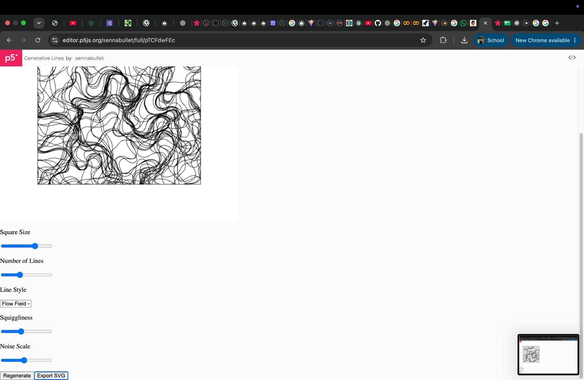
After experimenting with manually written G-code, I wanted to explore another way of creating patterns through programming. I decided to use p5js, a JavaScript library that allows me to create visual designs using javascript code.
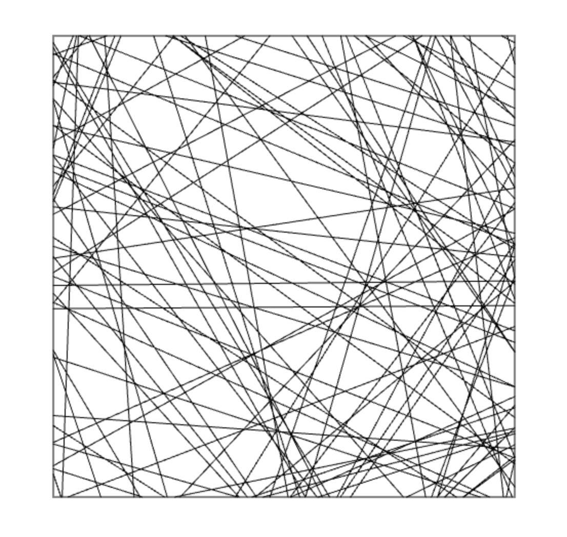
Instead of manually placing every element of a pattern, I experimented with random values to generate different arrangements. The interesting part was that I could define a set of rules and let the code produce variations. Even when I used the same basic idea, changing the parameters could result in a different pattern.
This made me think differently about the relationship between coding and design. Rather than drawing every detail myself, I could use mathematical rules and randomness to explore possibilities that I might not have thought of manually.
However, translating a digital pattern into a physical print came with its own challenges. During my first random-pattern printing experiment, I set the Z-height too low. As a result, the vertical dimension of the design was not what I intended. This taught me that I need to consider the physical dimensions and printing requirements when preparing a pattern for fabrication, rather than focusing only on how it looks on the screen.
I also realised that randomness alone is not enough to create a successful print. I still need to define suitable dimensions, movement paths, and layer heights so that the printer can follow the design properly.
Step4. Printing the Random Patterns
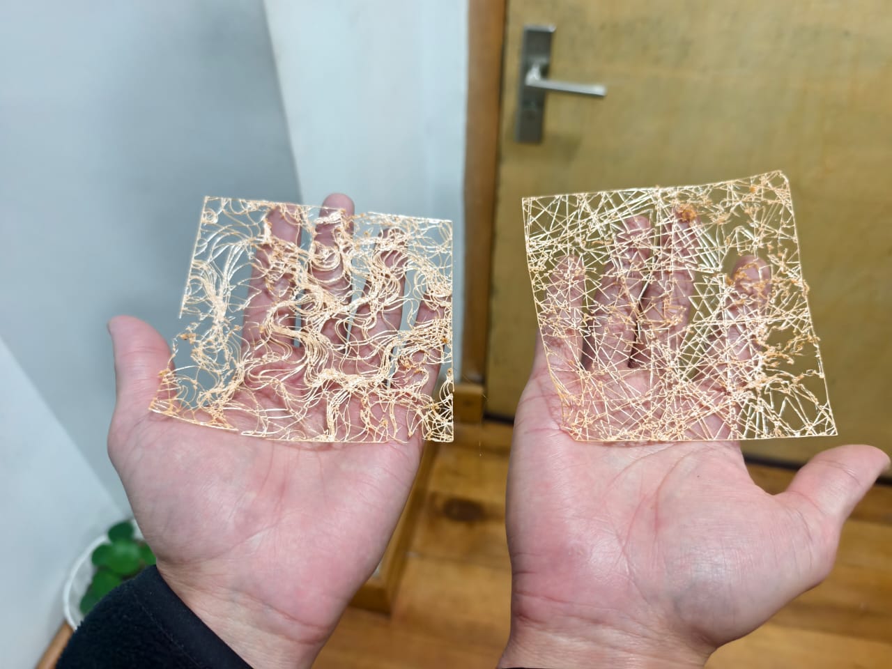
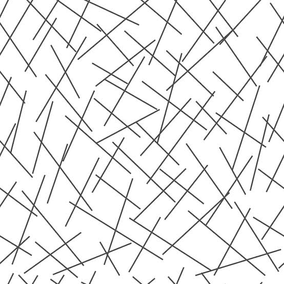
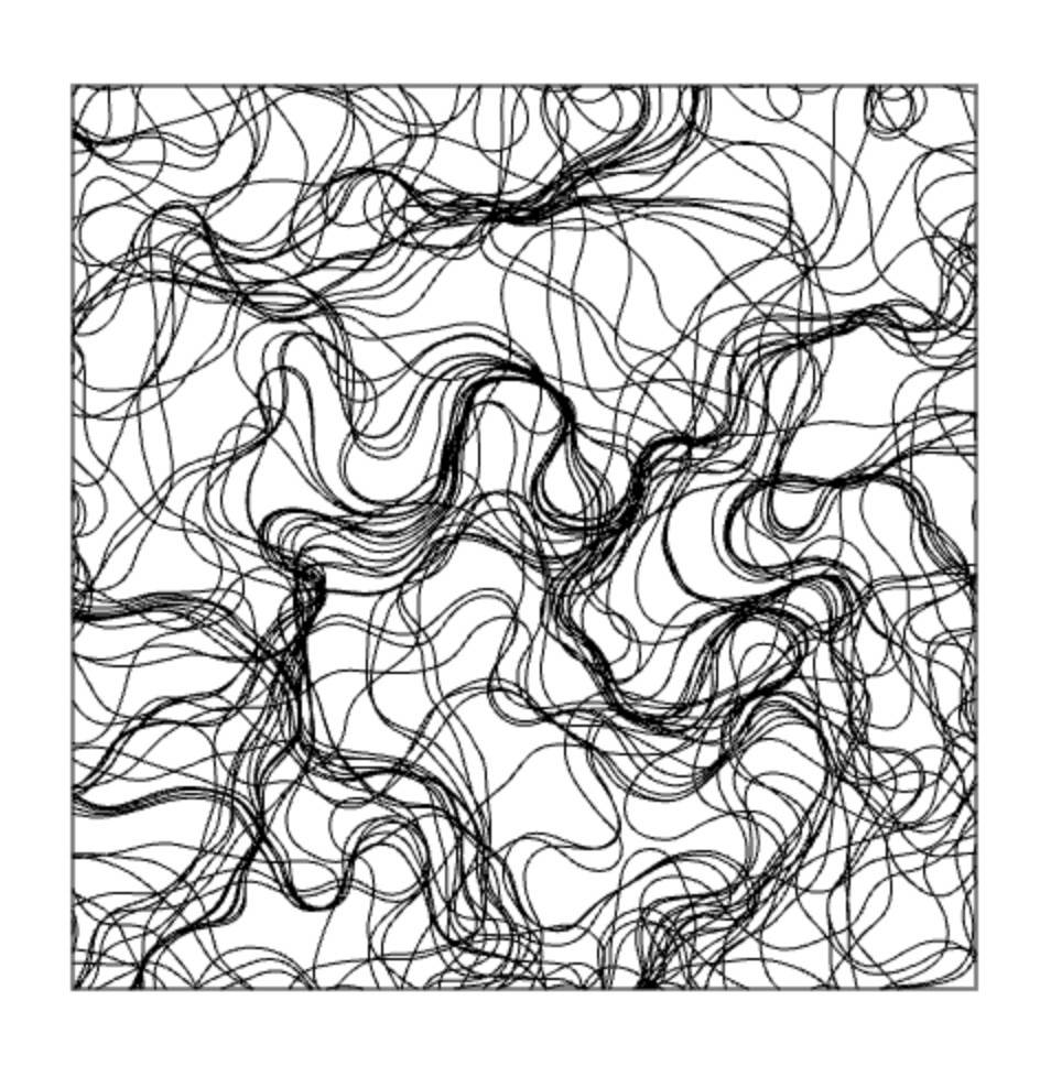
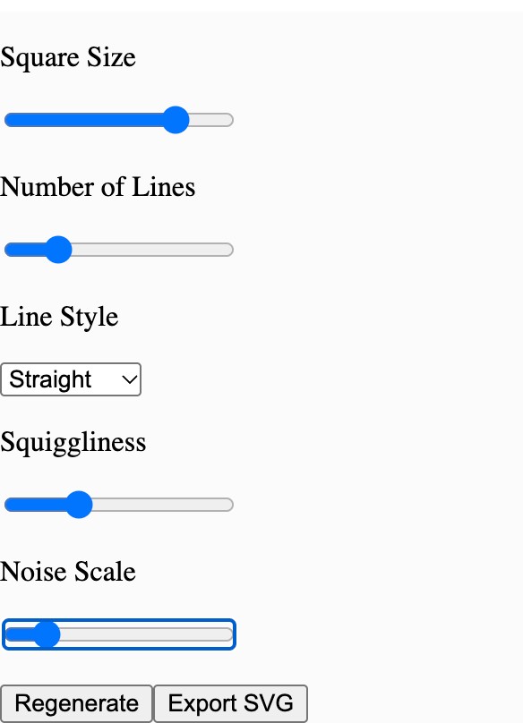
I generated two patterns using p5.js: a squiggly line pattern and a random straight-line pattern. I exported both designs as SVG files and imported them into the slicer to make some adjustments before printing.
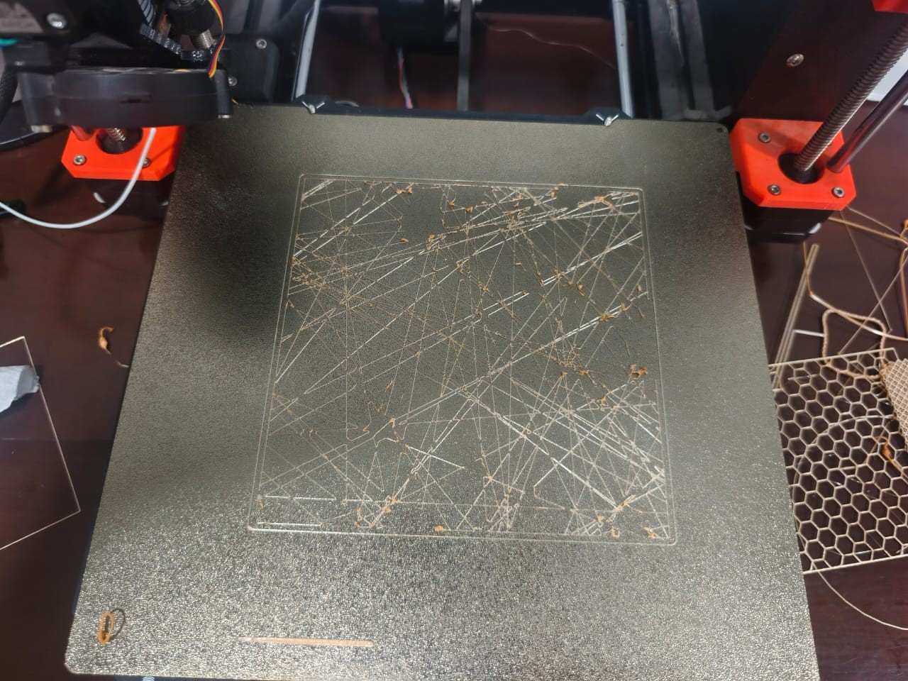
I printed the random straight-line pattern first, but I made a mistake when setting the height of the pattern. As a result, the lines did not stick properly to the print bed. After correcting the height settings, I printed the pattern again and got a good result. This helped me understand the importance of setting the correct height to ensure proper adhesion during printing.
When I moved on to printing my patterns, I encountered another problem. I had not checked the bed levelling carefully before starting the print, which affected the first layer. I had been concentrating on the design and the G-code, but I overlooked the importance of checking the physical setup of the printer.
This experience reminded me that even if the code is correct, the final result still depends on the condition and calibration of the machine. The nozzle needs to be at the correct distance from the bed, and the first layer must adhere properly for the rest of the print to succeed.
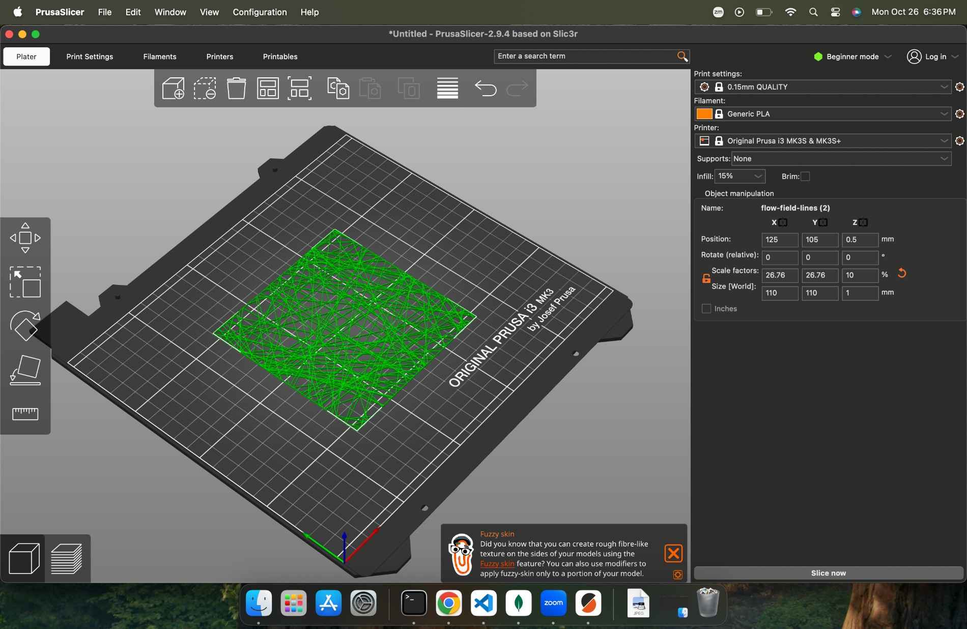
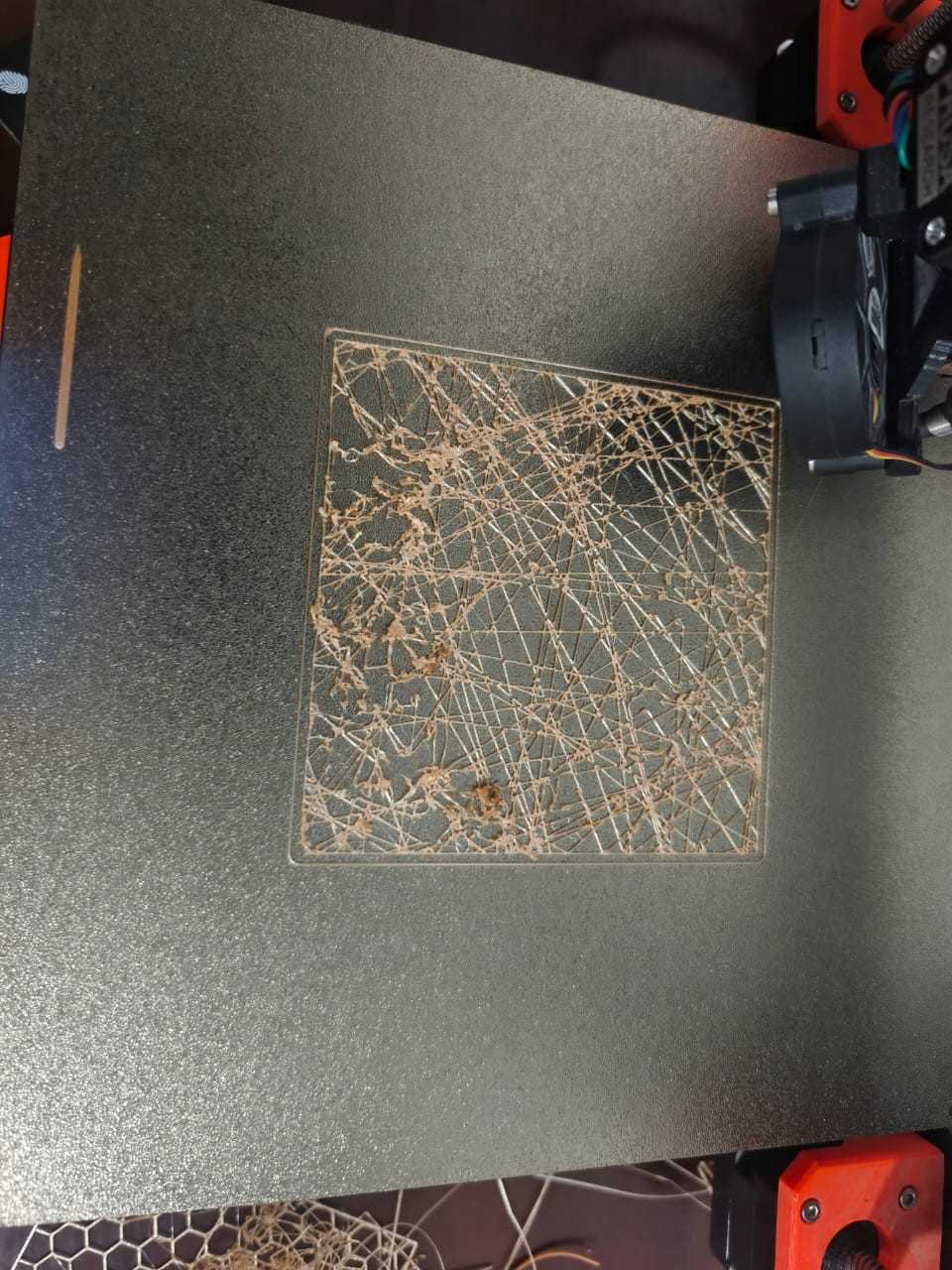
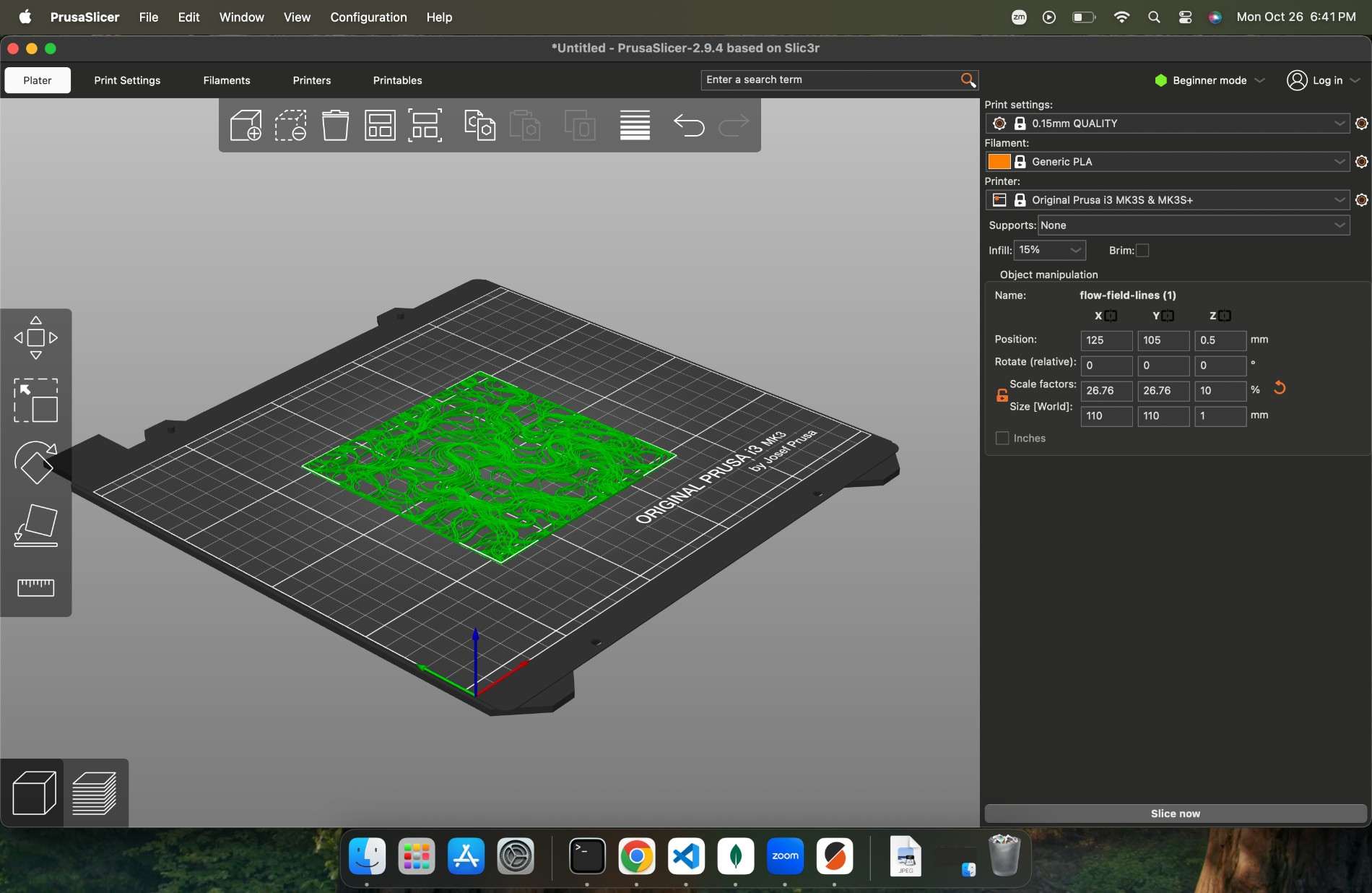
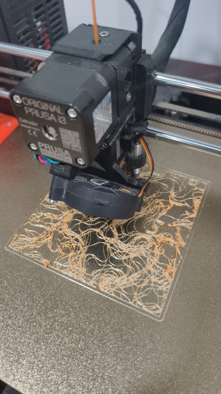
with the straight line pattern i did check the height of the filament i did not go the first result at first which wa s my mistke, so i suggest the setting
I also became more aware of the difference between bed levelling and Z-height calibration. Bed levelling compensates for variations across the print surface, while Z-height calibration helps establish the correct distance between the nozzle and the bed. Both are important when preparing the printer.
From this mistake, I learned to be more mindful before starting a print. I need to check the bed, confirm the printer's calibration, and observe the first layer carefully rather than assuming everything is ready.
Although the experience was frustrating, it helped me understand that 3D printing is not only about designing a model or writing code. It also requires patience, attention to detail, and an understanding of how the machine behaves in the real world.
Step5. Reusing Leftover Filament with a Heat Gun
For my final experiment, I wanted to explore what I could do with the leftover filament instead of simply throwing it away. Since I was interested in the concept of zero waste, I thought it would be interesting to reuse the material and turn it into something new. This was the inspiration i got from the
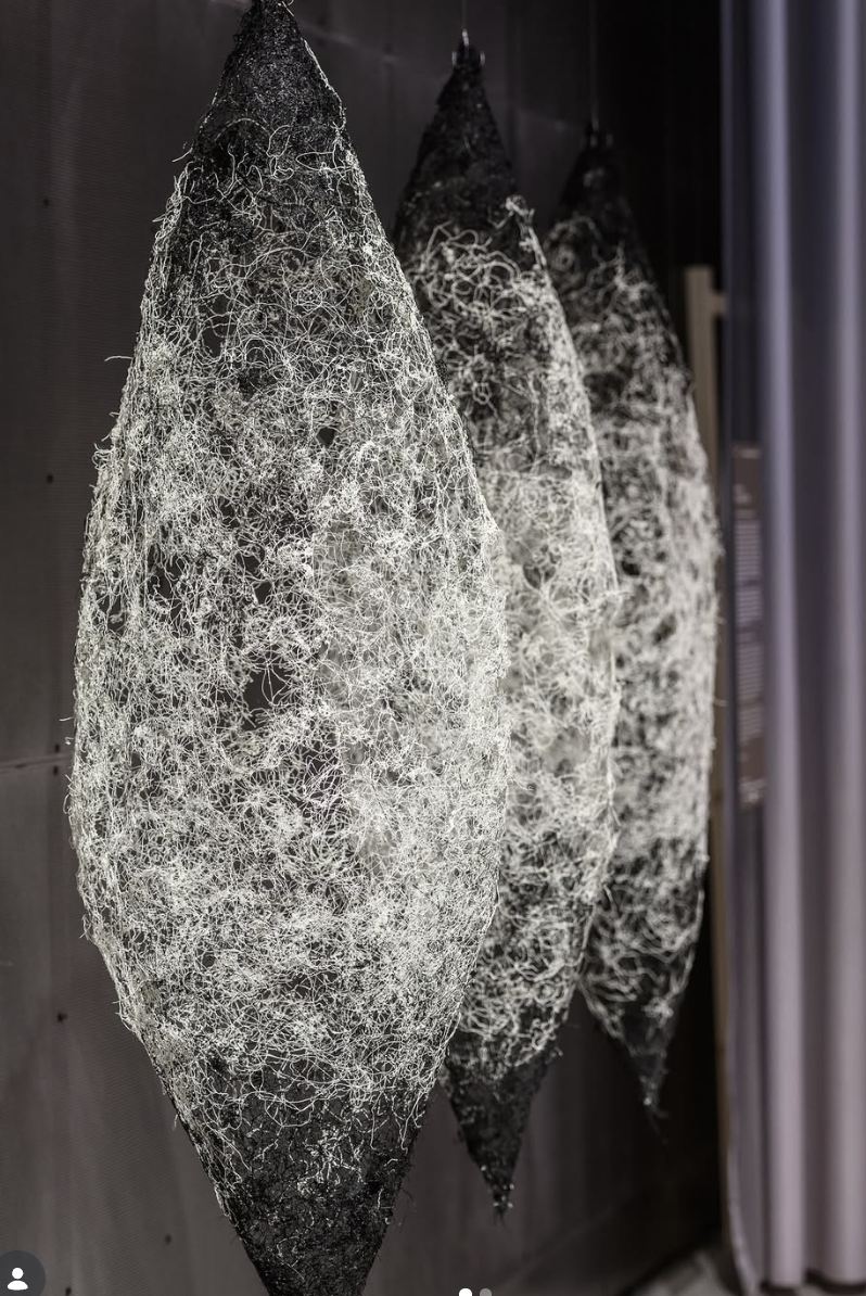
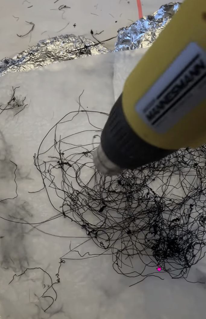
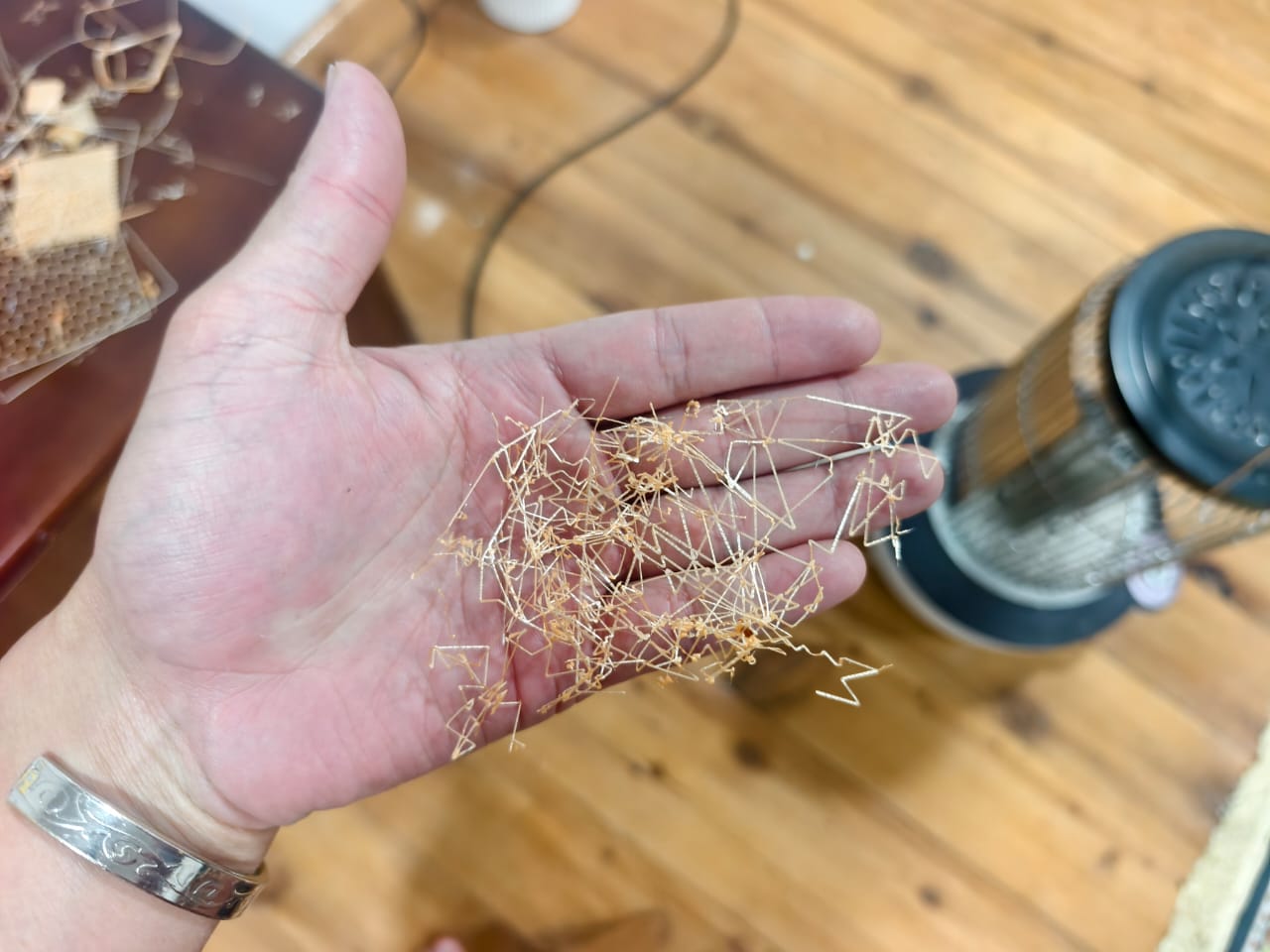
I collected some leftover filament from the printing process and experimented with a heat gun to soften and manipulate it into another pattern. Instead of treating the leftover filament as useless material, I wanted to see whether I could give it another purpose.
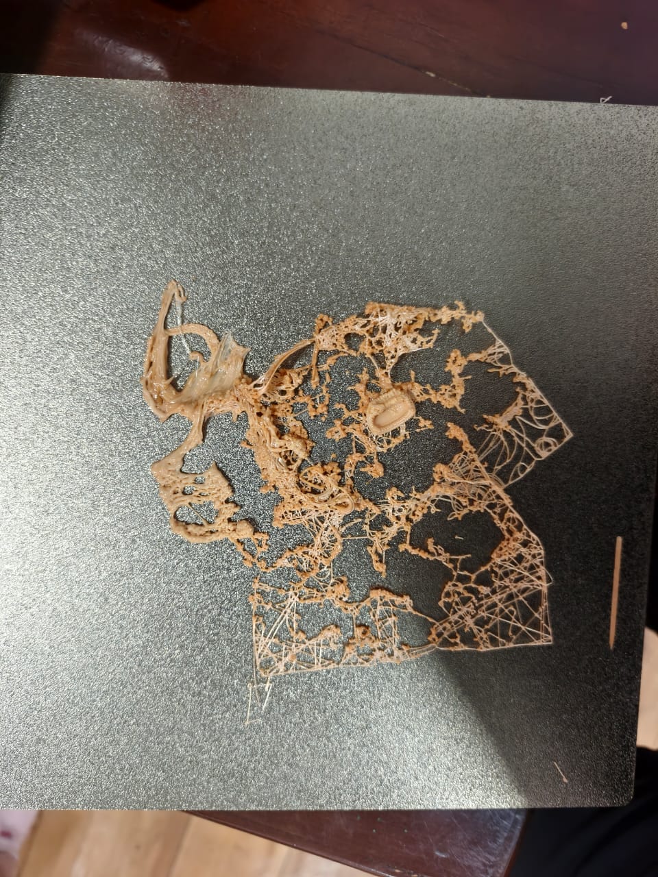
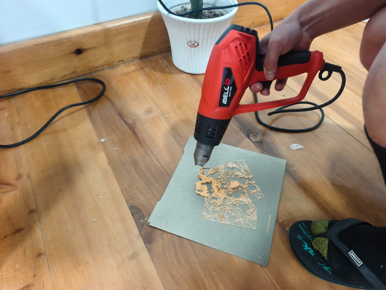
This experiment made me think beyond the conventional 3D printing process. Usually, the focus is on the final object, but there can also be opportunities to experiment with the material left behind. Rather than discarding every failed print or leftover piece, we can explore ways to reuse it in other forms. But i could not get the expected patternas it got burned with filament beause of not having good controlling in hot gun, although this was only an initial experiment it gave me ideas about how leftover materials could become part of another design process.It also connected with the concept of zero waste, where we try to reduce unnecessary waste and make better use of the resources available to us.
Weekly reflection & critical thinking
-
Looking back at this week, I feel that I learned much more than simply how to operate a 3D printer. I started exploring how G-code works, how mathematical coordinates control the printer, and how programming can be used to generate patterns.
-
The custom G-code experiment was particularly interesting because it allowed me to look beyond the slicer and understand the instructions behind the printing process.
-
I still want to explore Blender Geometry Nodes and learn how to generate more complex parametric patterns that can be translated into G-code.
-
Most importantly, this week encouraged me to experiment rather than depend entirely on existing tools. I also began thinking about how leftover materials could be reused instead of wasted, though the result is not as expected.
Tools
Fabrication files & References
-
File: Gcode for straight pattern ↩
-
Reference: Sara; E-textitle; fabricademy.io; 2021 ↩
-
Reference: Mina's;E-textitle; fabricademy.io; 2024 ↩