E-textiles
Final work of this week
The work I did this week was exploring with analog and digital sensors embedded in textiles. The way I materialized it was in the form of a measuring glove, with which you can measure objects or distances just using your hand.
The following video shows how the glove registers an increment in distance every time the finger tips touch.
Get the code!
The full code is stored in Github
Inspiration and concept development
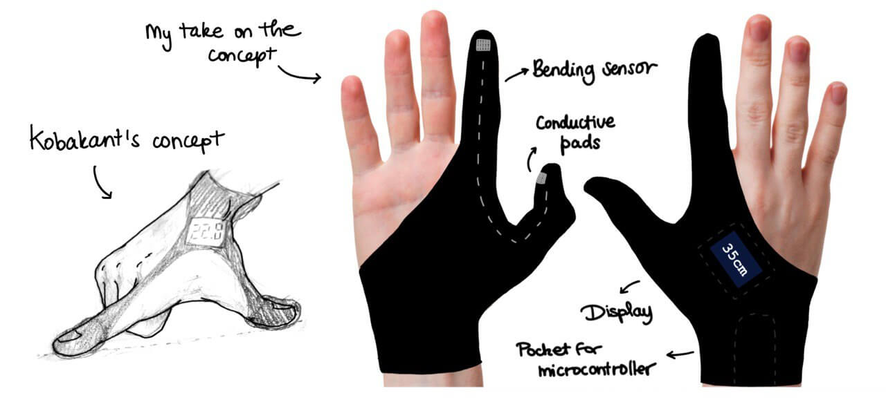
The idea of a measuring glove isn't my own. As I was looking for a project to use e-textiles, I browsed on the collaborative page Kobakant, which has the most extensive library of concepts, tutorials and ideas in this topic. I found a section of the website in which people can ask for tools or gadgets they'd like to have. One of them is this measuring glove.
And while it is quite a challenge as a first project with e-textiles, I wanted to give it a go and see how far I could get during the e-textiles week.
Option A: Bending sensor
Option A is to use a bending sensor to record the angle between the index and thumb fingers when doing the measuring motion.
Knowing the angle between fingers, the distance between the tips can be calculated. However, a couple of questions come to mind:
- Is this kind of sensor accurate enough to calculate a measured distance?
- Is the response of the sensor linear with respect to the angle of the fingers?
Option B: Binary switch
In case the bending sensor doesn't work, there is another way to approach the problem. It provides a coarser measurement, but it is easier to implement. The idea is to place conductive pads on the tip of the index and thumb fingers. At the end of each measuring motion index and thumb touch each other. If I can record these contacts with an Arduino and I know the distance between finger tips in fully extended position, I can calculate the measured distance: # contacts x index-thumb distance.
Experiments during class
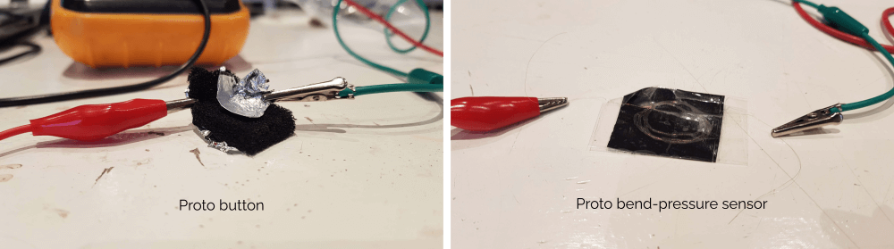
During the lessons with Emma and Liza, we had the chance to build our own proto-sensors and actuators. First we built a button! By sandwiching a perforated piece of ESD foam with two small sheets of aluminum paper, we were able to make a functioning switch. We tested it by checking continuity with a multimeter. The way to use it is simple: press it hard enough, and the aluminum paper on the sides will make contact through the ESD foam, therefore creating a conductive path.
After this, we built a rudimentary bend/pressure sensor. This sensor has two strands of conductive thread separated by a layer of Velostat fabric. You can measure the resistance of this device with a multimeter, and see that it drastically changes its value when it is bent or pressed. Thererfore, it works as a variable resistor dependant on pressure.
Development of the assignment
Special materials
Conductive thread
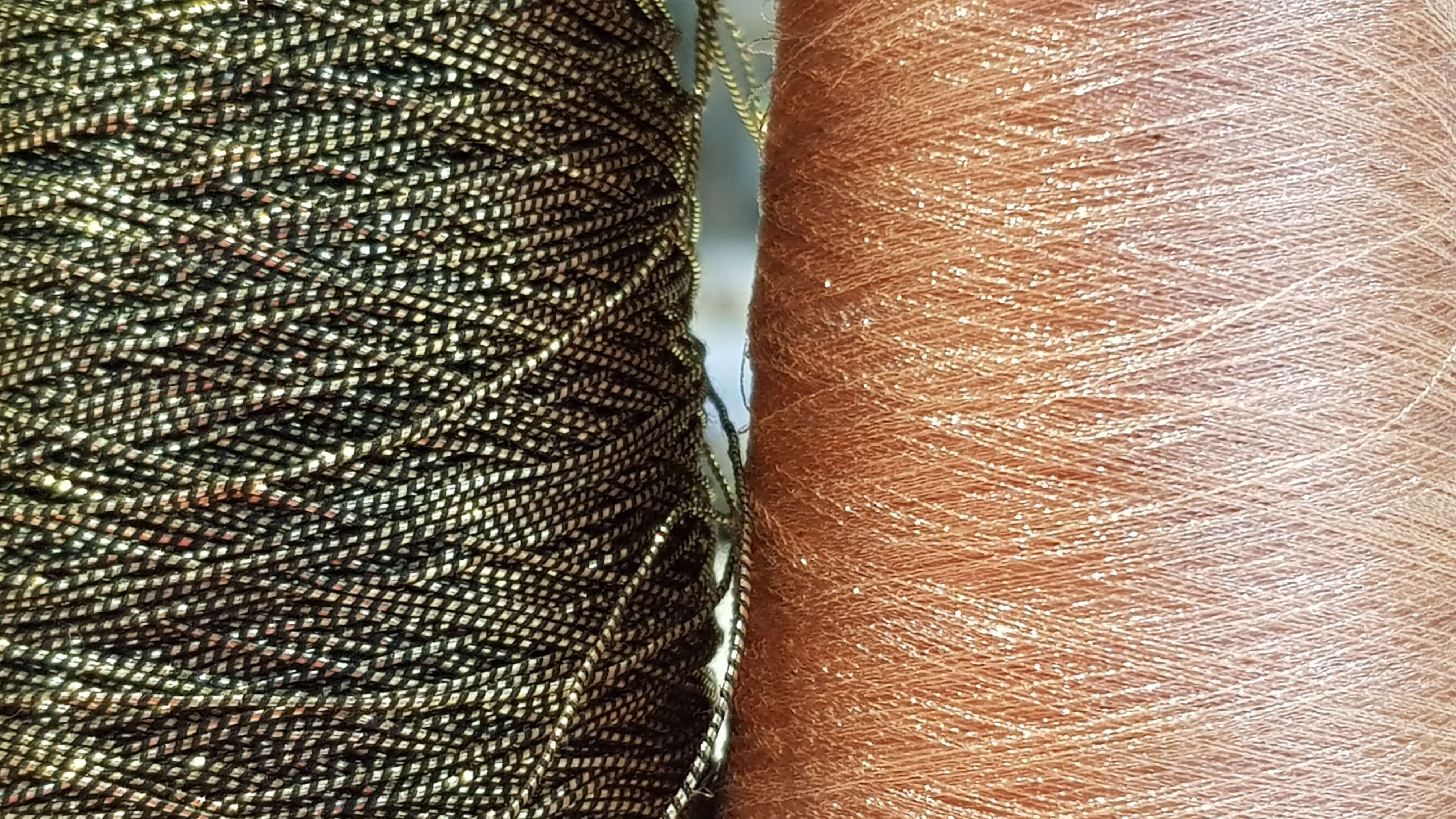
There are several kinds of conductive thread. They can be mainly distinguished by how they are built, the kind of metal they cotain, and their resistance. I wanted to make an overview for myself of the available options at Waag, so I measured them with the multimeter and put the info in the table below.
Click to see the different conductive threads resistances
| Thread | Resistance per 10 cm (ohm) | Resistance per cm (ohm) | KOhm per cm | MOhm per cm |
|---|---|---|---|---|
| Egyptio | 1 | 0.1 | 0.0001 | 0.000001 |
| Inox steel thread (radio conductive) | 95 | 9.5 | 0.0095 | 0.000095 |
| Touchscreen yarn | 1000000 | 100000 | 100 | 1 |
| E-Textile metal thread (inox steel microfibres) | 1900000 | 190000 | 190 | 1.9 |
| Aluminium | 2200000 | 220000 | 220 | 2.2 |
| Copper | 3500000 | 350000 | 350 | 3.5 |
Velostat
Velostat is a material made out of plastic that contains carbon black, which turns it conductive. What makes it especially interesting is that its resistance changes when bending or pressure is applied. Namely, the resistance decreases when one of these actions is performed on the material.
Arduino
For the measuring glove, a microprocessor is needed to interpret the signals recorded from the sensor and translate them into something useful. I chose to use an Arduino Micro because it is quite powerful while being small.
Option A: Bending sensor
Initial concept and design
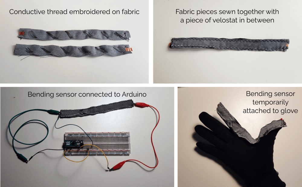
I started with the documentation from Kobakant as a basis. It consists on two pieces of fabric with embroidered conductive thread. Then these pieces of fabric are sewn together with a strip of velostat of the same size in between. Source: Kobakant

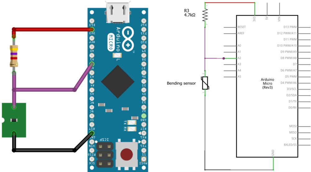
And this is my concept for the circuit:
Development
I put together the bending sensor by sewing conductive thread (Egyptio) on two separate pieces of fabric, then sandwiching them with a piece of Velostat in between. Afterwards I used the sewing machine to fix all the layers together. Finally, I connected the sensor to an Arduino to have a look at the measured values.
Code behavior
The Arduino is programmed with the following logic:
- For the first five seconds after the Arduino is turned on, read the values from the bending sensor and record the maximum and minimum obtained. This is the calibration phase.
- After this, in a loop, read the value of the bending sensor and map it with the calibration values.
- Use the mapped value to regulate the luminosity of a led.
The full code is stored in Github
In the following video you can see the behavior of the sensor at this stage of development.
First issue: unstable values from the analog sensor
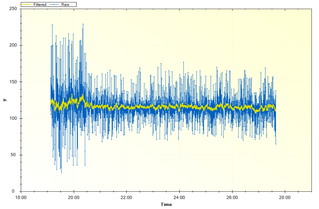
The first issue I encountered was that the values read with the Arduino were very unstable and noisy. I first tried using the smoothing method suggested on Arduino tutorials, which consists of sampling 10 measurements and calculating their average. Although this method improved the results a bit, I went a bit further and found how to use an exponential filter from an existing Arduino library. This method proved to work quite well, although it introduces some delay in the processing of results. However, that shouldn't be an issue for the purpose of this project.
Raw versus filtered sensor values using an exponential filter
Every time you provide a new value (xn), the exponential filter updates a smoothed value (yn):
yn = w × xn + (1 – w) × yn – 1
Where:
- yn is the output of the filter at a moment in time n
- xn is the new input value at a moment in time n
- yn – 1 is the previous output value of the filter
- w is the weighting factor in the range [0, 100].
Second issue: recorded values are very sensitive to calibration
The code is written so that each time the Arduino is turned on, it reads the values from the bending sensor and records the maximum and minimum. This is used as calibration to map the read measurements within that range when using the glove. The problem I encountered is that this calibration produces very different results each time, making the use of the glove quite unpredictable.
What this means is that if calibration is done correctly, it is possible to distinguish between the extended index-thumb position and the closed index-thumb position. However, it is extremely difficult to calibrate it in order to obtain this behavior.
I haven't found a solution to this yet, and I think there are multiple reasons why this may be happening. These are my hypothesis:
| Hypothesis | Ideas for next iteration |
|---|---|
| The conductive thread I chose has very low resistance. In the documentation of Kobakant is explained that the bending sensor should have a resistance of around 2MOhm when resting. In order to get to that value, I had to use multiple strands of thread to form a path with sufficient resistance. My suspicion is that this makes the sensor quite unstable, as there are multiple threads changing their contact points when the sensor is moving. That could be the reason why I get spikes and unstable readings in the measured values. | Make the bending sensor again, but this time using a thread with more resistance. That way I can use a single strand of thread, which could help in getting a stable signal. |
| The sensor is too long for the behavior that needs to be measured.When I attached the sensor to the glove, I noticed that the area I am really interested in is the inner curve where the index and thumb fingers join. I don't need the sensor to cover the entire length from index tip to thumb tip. | Make the bending sensor long enough to cover only the lenght between the index and the thumb knuckles. This could also help in getting more stable range of values during calibration. |
Option B: Binary switch
Initial concept and design
My first idea was to follow the instructions on Kobakant to make a fabric button.
However, for the measuring glove I believe having conductive pads on the tips of the index and thumb fingers is enough, since the movement of the fingers while measuring will make a brief contact between the tips of the fingers. Therefore, I need the contact to happen easily so it can be registered by the Arduino.
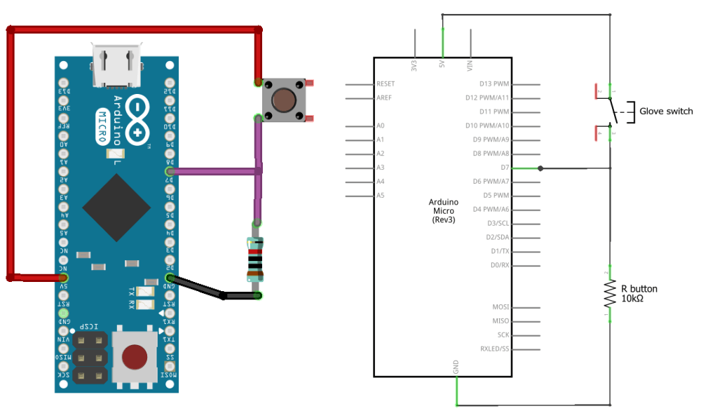
This is the concept behind the conductive pad switch and how it connects to the Arduino. The button that is represented in the schematic corresponds to the conductive pads on each finger tip. When they touch, the circuit is closed and so it can be measured.
Development
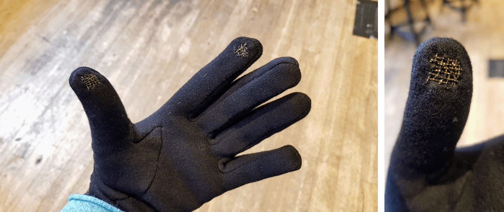
I started by embroidering some Egyptio thread in the thumb and index finger tips of the glove. That thread tends to unravel when it is manipulated, so it broke a few times while hand sewing it.
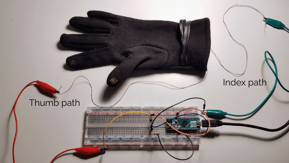
When connecting the glove to the rest of the circuit, it looked as in the picture below.
I did a first test with the led that's on top of the Arduino board to confirm everything was working as expected.
After that, I checked and adjusted the code to count correctly the measurement done with the glove (number of times index-thumb contact * index-thumb measurement in extended position).
Code behavior
The Arduino is programmed with the following logic.
In the setup part of the code, two things happen:
- The base unit distance is set. This is the distance between index and thumb tips in extended position.
- The total measured distance is set to 0. This variable is used to record the accummulated distance measured.
In the loop part of the code, these events happen:
- The digital input of the "button", a.k.a. finger tips, is read: either it is connected (1) or disconnected (0).
- Every time a connection is detected (1), one base unit distance is added to the total measured distance.
If the Arduino is reset, the measurement count is set to 0 again.
The full code is stored in Github
Overall, this method works quite well (yay!). Next steps are:
- Make the connection of the glove to the rest of the circuit more sturdy.
- Integrate circuit and power source into the glove itself, so there's no need to be plugged to a computer.
- Add a display on the glove to be able to see the measured distance.