5. E-textiles
This week was SO FAR OUT of my comfort zone so I'm very proud that I have made it to the end of the week with a final product.
This was my teacher Rico's strong week, so thanks to him, it went a lot smoother than I had orginally feared.
Liza Stark's presentation was a great starting off point to get introduced to the ideas of this week. But just to note, it wasn't until the second or third time I went through her slides that I could actually connect the dots.
While this week felt a little like a really meticulous refresher of a junior year physics class I had in High school, nearly 10 years ago -- bittersweet in a lot of ways -- I was introduced to a whole bunch of new concepts and ideas, especially in the realm of soft-electronics. I can't wait to see what more I can create!
For now, check out my documentation for week 3. Starting off with a CRASH COURSE on ELECTRONICS.
Learning Outcomes and Student Checklist
Learnign Outcomes
+ Research skills: the participant has acquired knowledge through references or replicating existing projects
+ Design skills: the participant understands how to produce soft circuits, sensors and actuators
+ Fabrication skills: Learn how to embed electronics on fabrics, study soft-hard connections
+ Process skills: Anyone can go through the workflow, understand it and reproduce it
+ Final outcome: The assignment is assembled and either complete or tested
Student checklist:
[x] Build at least one digital and one analogue soft sensor, using different materials and techniques
[x] Document the sensor project as well as the readings got using the AnalogRead of Arduino
[x] Integrate the two soft sensors into one or two textile swatches using hard soft connections
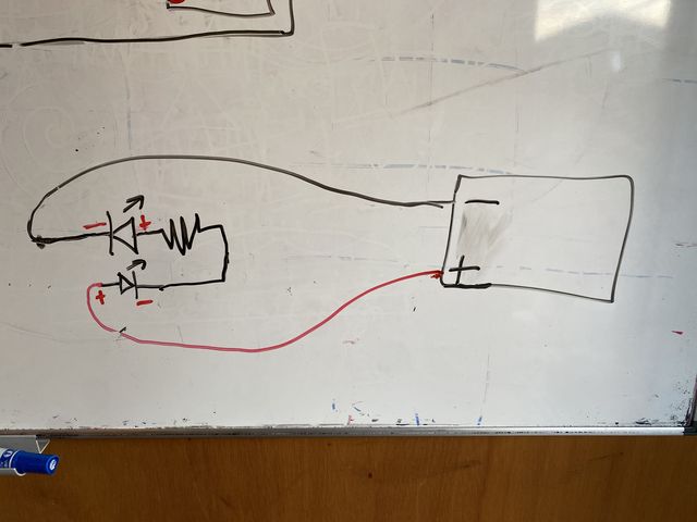
[x] Document the circuit and its schematic
[x] Document your swatches / samples
[x] Upload your arduino code as text
[x] Upload a small video of the swatches functioning
[x] Integrate the swatch into a project (extra credit)
CRASH COURSE ON ELECTRONICS
Electricity
This week we are going to learn how to make E-TEXTILES: conductive or resistive textiles and threads with a soft electronic circuit.
An electronic circuit needs a (+) and a (-), in other words Power (+) and Ground (-), for electricity to flow.
Electricity flows from Power to Ground, from (+) to (-): this is called Polarity.
An electronic circuit follows OHM’s LAW: V = I x R
V= Voltage (Unit: Volts)
I = Current (Unit: Ampere, or A)
R = Resistance (Unit: Ohms or Ω)
Voltage: Pressure, potential of current, difference between beginning point and end point (Power-Ground).
Current: Rate of flow of electricity from Power to Ground
Resistance: Anything that slows down the current, or rate of flow
MCU (Micro Unit Controller)
We will add load(s) or sensors to our circuit that will inform our Micro Unit Controller (MCU) to perform a function that we’ve programmed.
The Micro Unit Controller (MCU) I will be using this week is called the Arduino Uno. As a result, I will program my code into the Arduino IDE, which I’ll then upload into my MCU for it to perform its function in my circuit.
Input Sensors
This week, we will try to program two different types of input sensors: a digital one, and an analog one.
An Input sensor is an electronic device that senses the environment or human interaction. It senses data and sends it to the MCU for processing via electrical signals.
A digital input sensor is like a Switch. It is a binary state: on/off, or in the case of the Arduino (0 Volts/ 5 Volts). OFF= 0 Volts, ON= 5 Volts.
An analog input sensor is like a Volume Knob. A gradation of states between the minimum and maximum values.
There are many different kinds of input sensors that are available to work with this week. Liza Stark, our instructor for this week, outlined a great list of sensors in her presentation, including:
Analog Sensors
- Pressure sensors
- Bend sensors
- Potentiometer sensors
- Stretch sensors
- Accelerometer sensors
- Light-resistant sensors
AND
Digital Switches
- Momentary
- Toggle
- Tilt
- Stroke
REFS & INSPO
Get Inspired
-
Liza Stark
Soft Circuiteer Website
Personal Website
KobaKant Sensor Page -
Ieva Marija Dautartaitė
Her Fabricademy Website
Her Final Project -
Berenice Courtin
Third Week Assignment -
Irene Posch Embroidered Computer
TOOLS & PRACTICE
- Arduino UNO
- Arduino IDE
- MultiMeter
- Breadboard
- Conductive/Non-Conductive Material
- TinkerCad
Multimeter
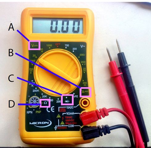
MultiMeter is a tool helpful to check the continuity of a circuit/ if a material is conductive, and measure voltage, resistance, and current.
A. DC Voltage (Volts)
B. Current (Amps)
C. Continuity Testing
D. Resistance (Ohms)
Arduino UNO
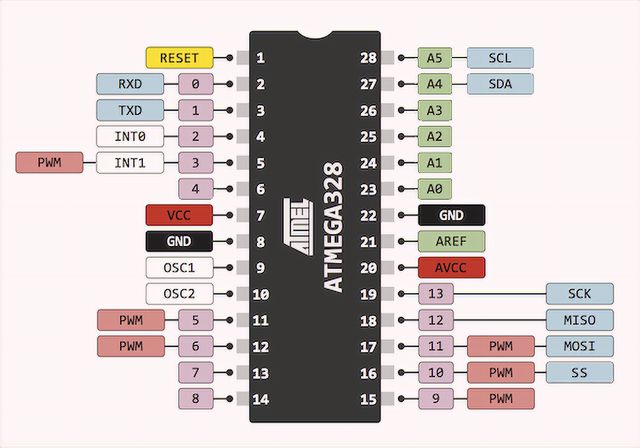 This is the actual Micro controller computer. And its called the ATMEGA328P.
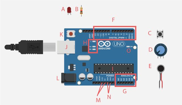 The Micro controller is embedded as the BRAIN of the Arduino Uno Development Board.
A. LED (Light Emitting Diode)
B. Resistor
C. Button
D. Potentiometer
E. Motor
F. Digital Ports -- INPUT OR OUTPUT (Digital output + Fake Analog outout)
G. Analog Ports -- INPUT ONLY
H. RX= Receiver, TX = Transmit, L= Test blink (also connected to pin 13)
I. MCU Chip: The Brain – ATMEGA328P
J. USB Port
K. Reset button
L. Battery/ Power Port
M. Voltage Port (+)
N. GND - Ground Port (-)
O. Arduino on/off light
PORTS/PINS All 21 GPIO pins can be Digital input/output. However, 6 of the pins have a special ability to also act as Analog Input Pins (A0-A5).
Of the remaining 13, 5 pins also have the special ability of generating PWM (Pulse With Modulation) signals, aka Fake Analog Output signals.
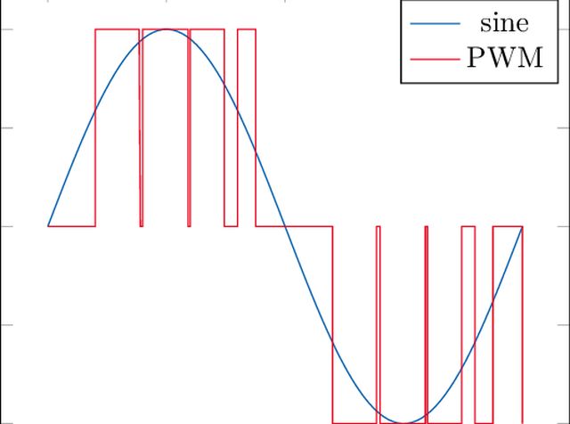 Blue = Pure Analog signal
Red = PWM = An approximation of an Analog Signal using Digital Output pin
Blue = Pure Analog signal
Red = PWM = An approximation of an Analog Signal using Digital Output pin
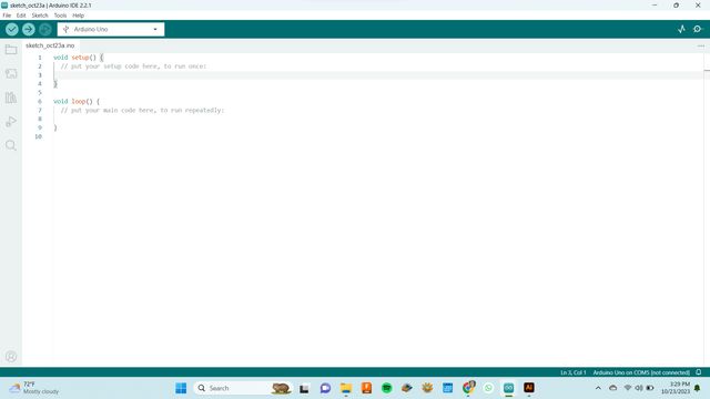
Arduino IDE
Download Arduino IDE here
-
Sketch = program in Arduino speak
-
function = think of functions as paragraphs. a block of code, contained within { curly brackets }. e.g. void(loop) {}
-
set up = a type of function that Runs once - settings, preferations, prepareation, configurations, think "set the stage"
-
loop = a type of function that Runs repeatedly - will not stop until power is removed, think "groundhog day"
-
// = comment NOT processed by computer. For humans to read/ make notes. TIP: ctrl + / to turn an entire line of code into a note
-
commands = think of commands as verbs. all commands have parameters, most of the time, the first parameter is the pin number. Here is a list of all the other commands for Arduino, and the amount of parameters they require.
-
variables = at the top of your sketch, it is reccomended that you enter your variables. some are constant, some are variables that change during the time your program is running.
- const int = variables that don't change during the programming time, such as the pin numbers connected to your electric devices
- int = variables that do change, such as Value of Potentiometers
Tinkercad
Tinkercad is a great way to practice using an Arduino UNO virtually. The Positive is called Anode (+), the negative is called Cathode (-).
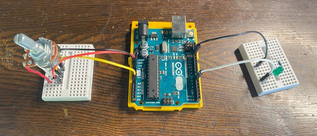
This is an example of me controlling an LED light with a Potentiometer on Tinkercad.
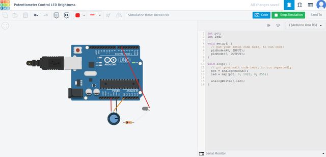
A Potentiometer is a Variable resistor. The knob in this example is the potentiometer.
Because its an analog input device, I connected it to one of the Arduino's analog input pins.
Serial Monitor
Serial Monitor is a display tool in Arduino IDE. It's useful for knowing what's happening in your program in real time.
It's a good debugging tool. Like a speedometer / status display monitor.
I used it to track the analog input signal levels.
To start and observe the Serial Monitor, you need to write the following lines of codes :
Serial.begin(9600)
Serial.println(...);
Example of Serial Monitor
With LED and Potentiometer Knob
CODE FOR INPUT SENSORS
LED Control with Potentiometer (Analog)
// during program run doesnt change
const int knob = A0; //knob signal connected to A0
const int led = 6; //led signal connected to 6
// during program run , changes --> these are the Variables
int knobValue; //how much i turn the knob
int ledValue; //how bright the light
void setup() {
// put your setup code here, to run once:
Serial.begin(9600); //start serial monitor
pinMode(knob, INPUT); //set knob as input
pinMode(led, OUTPUT); //set led as output
}
void loop() {
// put your main code here, to run repeatedly:
knobValue = analogRead(knob); //analogRead (1 parameter: PIN int) ... this tells the arduino to read a value from the knob PIN and assign to knobValue Variable
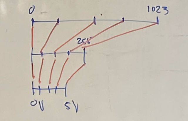
ledValue = map(knobValue, 0, 1023, 0, 255); // map(requires 5 parameters, PIN int first) ... this tells arduino to map a larger range of values into a smaller range of values, 255=MAX
analogWrite(led, ledValue); //analogWrite(requires 2 parameters, PIN int first) ... this tells arduino to send a certain amount of electricity (amount of Volts from 0-5) to led pin
Serial.println(ledValue); // print serial monitor in lines
}
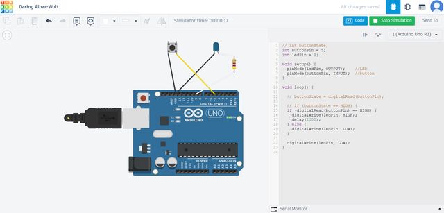
LED Control with Button (Digital)
// int buttonState;
int buttonPin = 5;
int ledPin = 9;

void setup() {
  pinMode(ledPin, OUTPUT);    //LED pin set as OUTPUT
  pinMode(buttonPin, INPUT);  //button pin set as INPUT
}

void loop() {

  if (digitalRead(buttonPin) == HIGH) { // if pin 5 is at 5 volts
    digitalWrite(ledPin, HIGH); // then send 5 volts to pin 9
    delay(2000); // wait 2 seconds
  } else {                      // otherwise...
    digitalWrite(ledPin, LOW); // send 0 volts to pin 9
  }

  digitalWrite(ledPin, LOW); // send 0 volts to pin 9
}
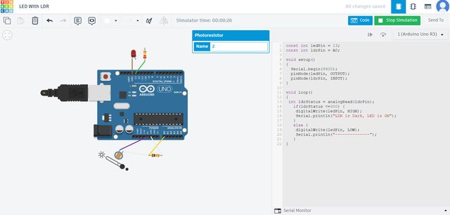
LED Control with LDR (Analog)
LDR = Light Dependent Resistor
const int ledPin = 13;
const int ldrPin = A0;

int ldrStatus;

void setup()
{
  Serial.begin(9600);   // start serial monitor at standard 9600 baud communication speed
  pinMode(ledPin, OUTPUT); //led pin set as output
  pinMode(ldrPin, INPUT); //ldr pin set as input
}

void loop()
{
 ldrStatus = analogRead(ldrPin); //read input from ldr pin and assign value to variable ldrStatus
   if(ldrStatus <=300) {        // if ldrStatus is less or equal to 300 out of 1023
    digitalWrite(ledPin, HIGH); // then send 5 volts to ledPin
    Serial.println("LDR is Dark, LED is ON"); // print to serial monitor the message in quotes
   }
   else {               // otherwise...
    digitalWrite(ledPin, LOW); // send 0 volts to ledPin
    Serial.println("--------------"); // pint to serial monitor message in quotes
   }
}
Motor Controlled with Solar Panel Potentiometer (Analog)
Depending on how much light the panel is receiving, the resistance decreases, more electricity flows. The MORE electricity flows, the FASTER the motor spins.
The coding for this one is the same as the previous potentiometer programming.
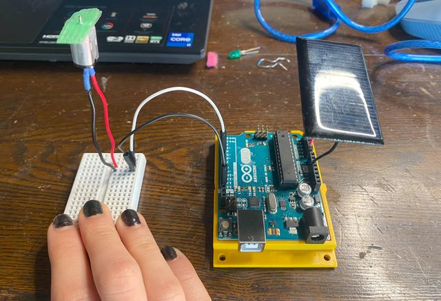
Potentiometer knob, solar panel and LDR devices are all examples of Variable Resistors.
MY FINAL SWATCH
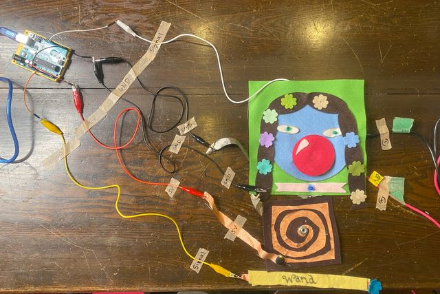
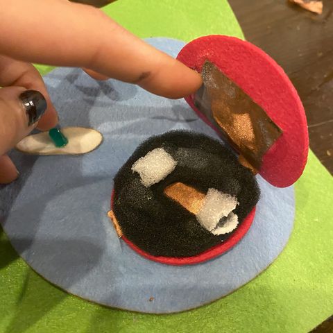
Button Sensor
This is an example of a Digital Momentary Switch.
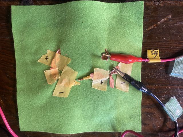
Spiral Sensor
This is an example of an ATTEMPTED Potentiometer variable resistance sensor.
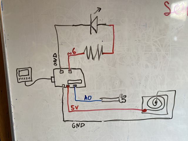
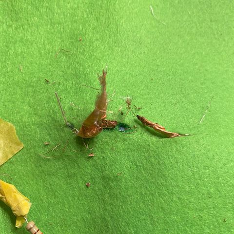
I had to make sure that my Copper fabric "wire" needed to clean and taped down so the frayed part wouldn't cause a short circuit.
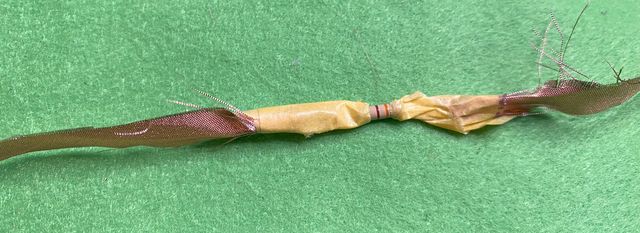
Like it did here... It overheated and burnt.
Notice that when the Serial Number prints a low number (in the 20s), the light is Dim. When the number reaches a high number (in the 200s), the light is Bright!
IT WORKS OKAY -- BUT NOT PERFECTLY.
Rico told me that I actually accidentally created an ANTENNA that generated a PULSING ELECTRO-MAGNETIC FIELD.
Therefore, in the Serial monitor, we observed values rising from 0 to 255 every 7 seconds.
When I have more time, I can try to figure out how to generate a more gradual modulation between 0 and 5 volts and vice versa.
My Code
const int wand = A0;
const int led = 6;

int wandValue;
int brightness;

void setup() {

Serial.begin(9600);

pinMode(wand, INPUT);
pinMode(led, OUTPUT);

digitalWrite(led, LOW); //set starting condition for LED as 0V

}

void loop() {

wandValue = analogRead(wand);
brightness = map(wandValue, 0, 1023, 0, 255);

analogWrite(led, brightness); //analogWrite command requires a PWM pin on Arduino

Serial.println(brightness);

}
Mapping ("brightness= map(wandValue, 0, 1023, 0, 255)") explained
Analog pins are 10 bit data pins; Digital pins are 8 bit data pins.
So we have to convert the 10 bit range of 0 to 1023 --> to an 8 bit range of --> 0 to 255.