Digital bodies
Final work of this week
Initial thoughts
Some of the things that come to mind when thinking about digital bodies are:
- How much is my identity linked to my body?
- How much does my digital self represent me?
- How much do I loan this identity to others when I digitize it?
- How distorted is the perception of my body compared to when I digitize it?
On a more practical sense, while looking into mannequins in general, I've stumbled upon the idea of adding texture to the mannequin. Not only making it about the volume, but about the tactile. In essence we experience the world through our body, could our digitized bodies extend that?
Flesh to digital to material
What are the side effects of the transformations?
What is lost in the process? What is gained in the process? Is there an attachment to any of these different forms of the body?
The act of observing yourself
I find quite interesting the fact that if you do the excercise of 3D scanning yourself, you are directly confronted with it, with those parts you like and those you don't. I take this as almost therapeutic, an act of looking towards oneself with the eyes of a stranger. Are we kinder or harsher to what we see when we don't fully identify it as our flesh?
Feeling vulnerable
And in case I do scan my own body, I also wonder how comfortable am I going to be when showing around my naked (digital) self. With clothing I have a sense of control of what I show, but my digital body is just me, bare.
Furthermore, how much of my digital self do I want to make available to others? What does sharing a 3D model of myself imply?
Inspiration
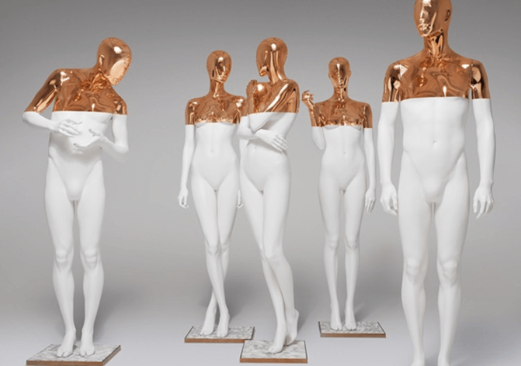
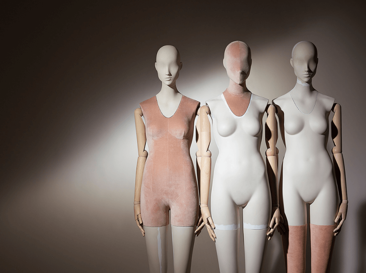
Hans Boodt
It is a Dutch mannequin manufacturer that focuses on made to order, high quality mannequins. They use 3D modeling as part of the process and they have a big focus in sustainability.
Digital bodies and Virtual Reality
Here's an example of how our virtual selves can start to experience the world for us in different contexts. The video is a recording of a concert in which the lead musician, a violinist, has a digital avatar reproducing her movements. The audience attends the concert using Virtual Reality technology, so their bodies are also digitally present in the concert.
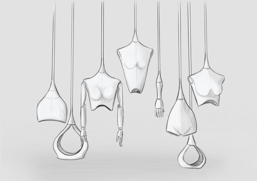
Bodies in motion
We saw during the lecture of Anastasia that some artists explore representing bodies in motion through their sculptures. I found something similar on Thingiverse.
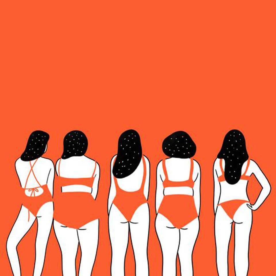
Agathe Sorlet

Personal goal of the week
I want to scan myself and explore what kind of emotions and reactions does the excercise trigger. Even more, I'm thinking on focusing the scan on those areas of my body I'm the least comfortable with.
Process
The overall process that I have experimented with is described in the table below, and the different steps will be explained further in the following sections.
| Input | Step | Output |
|---|---|---|
| Body or body measurements | Scan body or input measurements in Make Human | 3D object file (.obj) |
| .obj file | Import to Rhino to clean up the model | Clean 3D object (.obj) |
| Clean 3D object | Manipulate shape by scaling, rotating, chopping the parts that are interesting to your work... you name it | Modified version of 3D object in Rhino |
| Modified 3D object in Rhino | Export modified 3D object | New .obj file |
| .obj file | Import to Slicer for Fusion360, select material and slicing parameters. Export laser cutter files. | Laser cutter files (.dxf) |
| DXF file | Input DXF file in the laser cutter, and cut your material | Material cut in pieces according to assembly plan |
| Laser cut material pieces | Assemble following instructions from Slicer | Final piece! |
From flesh to digital
Experimenting with Make Human
The platform is nice to experiment but quite limited to body shapes outside of what they've programmed as the norm. If I input my own measurements, some of them are not allowed since the proportions are not deemed as valid. How nice, ha? It also perpetuates some gender and racial stereotypes that are quite old fashioned.
So I'm already biased towards Make Human as a tool to use. I'm going to call it Make Some Humans.
I present to you virtual Sara 0.1:
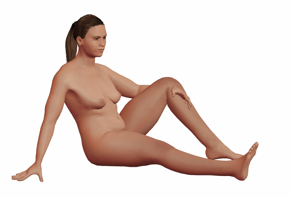
Conclusion
It is annoying that I cannot make a 3D model more similar to my actual body because of arbitrary limitations of the people that coded this tool. However, as you'll see later, scanning is no piece of cake either so I ended up using this model for the rest of the exercise.
3D scanners
As stated in the goal above, I wanted to work with my own body to explore the feelings and emotions that this would trigger. Scanning myself is the most obvious way to do this, as the machine won't mask anything that comes into its eyes. The 3D scanning process confronts you to your body two times: first by standing still while being closely observed by another person, second by having to see the reality of your volume on the screen of your laptop. There's nothing to hide there. The parts you like and those you don't are exposed and you get to look at them in a different way than you're used to.
To get a fairly uncluttered 3D scan of my body, I put on tight clothing so it wouldn't significantly alter my shape. Then I got in position (a slightly awkward standing pose) and my classmate Jen kindly scanned me with the 3D Sense scanner.

It wasn't an easy task, as the subject has to stand still for a long time while the person handling the scanner patiently goes around you. The process wasn't smooth since the scanner is quite sensitive to sudden moves. If the scanner is moved too fast, it will lose track of where it was scanning and it is necessary to look for a spot that it can recognize so the process can continue. To scan smaller volumes this isn't a big issue, but scanning a full body proved to be challenging and somewhat frustrating. In the end and after a few tries, we did a partial scan.
Manipulating the digital self
Manipulating the 3D object with Rhino
For the assignment I wanted to work with a full body 3D model, so I went back to the one modeled in Make Human.
Once I had a 3D model to play with, we were explained how to work with it in Rhino. The main goal was to select the parts of the body we were interested in for our final piece. That meant going through the following steps:
| Step | Command(s) |
|---|---|
| 1. Import .obj file to Rhino | Import |
| 2. Create a polysurface from the original mesh as this allows easier manipulation. | MeshToNURB |
| 3. Delete mesh | Click object with mouse, select mesh and press Delete. |
| 4. Create a box to cut your model | Box, draw limits in the visors |
| 5. Cut your model in two using the box created | BooleanDifference. Substract from the body model; substract with the box just created. |
| 6. Select desired body part and export to .obj | Export. It is important to check the box Save geometry only. |
Issues with MakeHuman exported .obj
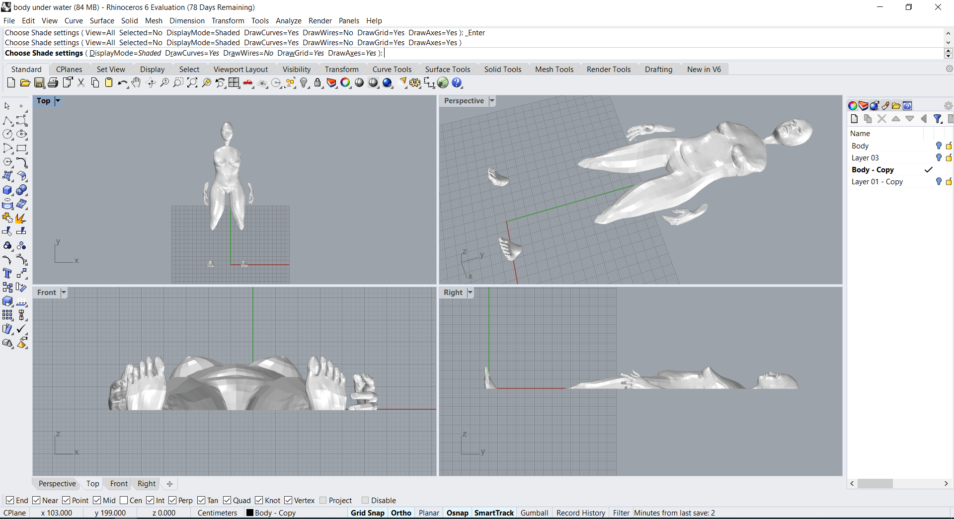
During the editing I had issues with BooleanDifference not working due to non manifold surfaces generated by MakeHuman. Later, I found out that the hair was causing these issues, so I removed it from the model.
The result of manipulating the 3D model was the following:
Useful tips
Besides the basic steps explained above, there are some tips that are useful to know when starting with Rhino:
- Once Rhino is open and active, you can type a command without having to click the command box.
- Pressing the space bar will call the last executed command.
- While creating or moving objects, pressing Shift key will change between orthogonal and free moving.
- If while working you run a few commands and you'd like to know what you did to get there, you can export the command history going to Tools > Commands > Command history
Extra: create a solid from an image
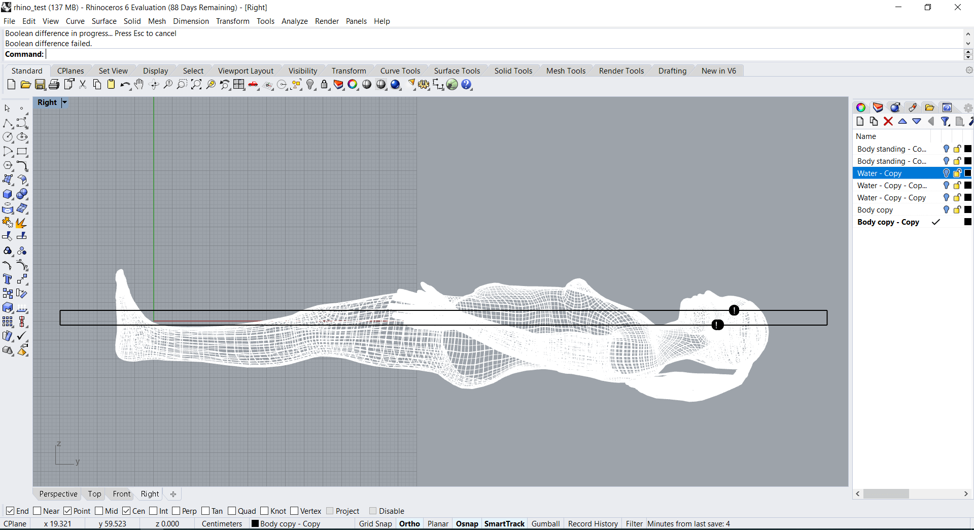
During the process of creating the final piece, I explored the idea of creating a surface with cardboard that resembled water. For that, I looked up how to convert a 2D image into a surface. Luckily, Rhino has this functionality so I just had to find a suitable image and run the command. There are also a few other details to consider when doing this.
The steps I followed were:
- Get the image you want to make into a volume. I used this one.
- Type Heightfield command in Rhino, and follow the instructions.
- To convert the resulting surface into a solid, run Cap command.
- If it doesn't work, you'll need to even the limits of your surface. One way of doing this is creating a box under the surface, enough to cover its whole area. Then run BooleanDifference so that you end up with a box with your desired surface on top.
Extra: twisting an object
At some point I also thought about twisting the torso of the model with Rhino. I didn't try it, but I found documentation on how to do it.
Materializing and assembling
Slicing for laser cutter with Slicer for Fusion360
With the final 3D model file the next step is to prepare it to be materialized. We used Slicer for Fusion360 to convert the generated solid into a blueprint for the laser cutter.
| Step | Command(s) |
|---|---|
| 1. With Slicer open, import the desired .obj file | Click Import and select file in browser. |
| 2. Create a new set of manufacturing preferences | Click the pencil button. On the pop-up window click the + button at the bottom. You will need to insert the dimensions of the material you are using. In my case, I used cardboard. The dimensions I had to introduce were: lenght: 1160 mm; width: 760 mm; thickness: 3 mm. The rest of the parameters set to 0. |
| 3. Make sure the size of the object is correct | Look at and modify if needed the measurements in the Object size menu. |
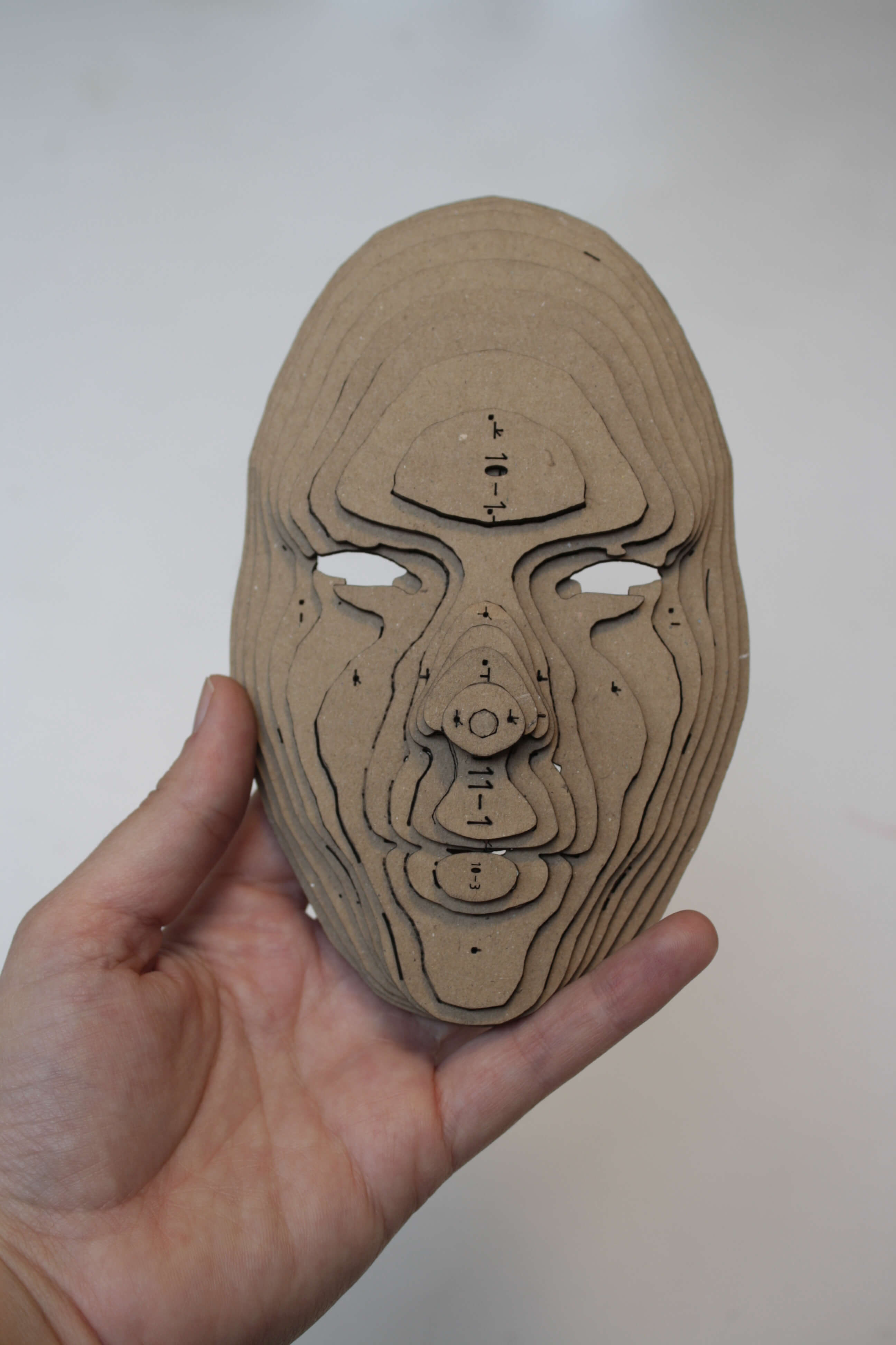
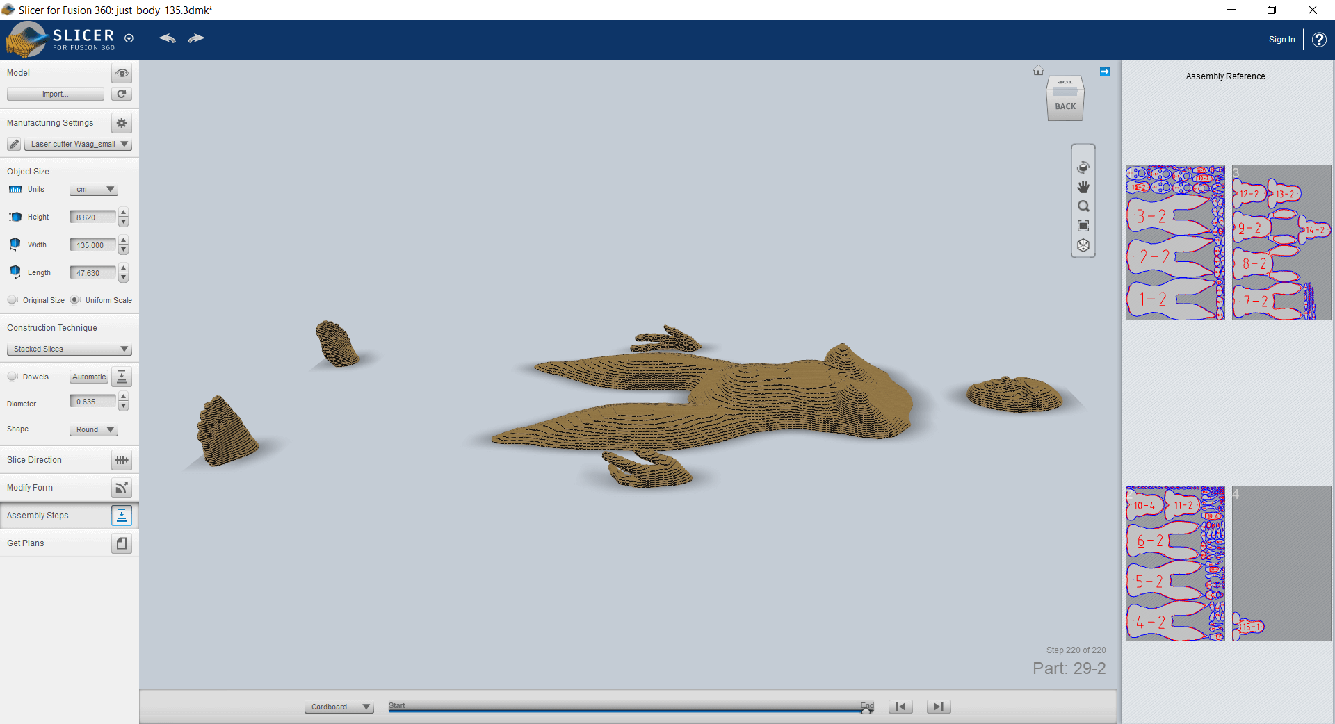
| 4. Select a construction technique and check the amount of pieces and used material | In the dropdown several options can be selected. Once you've selected one, the program will calculate (and you will see) the amount of material needed using the parameters of the manufacturing preferences. I used Stacked Slices. This method uses more material than the others. We were given an allowance of 3 cardboard sheets, and with a slighly scaled down version of my model I could fit it in this quantity. |
| 5. Customize slicing parameters | Using the provided menus, it is possible to customize the slicing. For instance, the orientation of the slices. I made sure the slicing was done parallel to the bottom part of my model. |
| 6. Check for errors in the sliced model | The program will warn you on the right side about possible errors that will make your manufactured object impossible to put together. These errors can be solved by tweaking the slicing parameters, like the slicing orientation or number of axis or curves. |
| 6. Export sliced model to DXF files | Click on Get plans button. Select DXF as format and mm as unit. Then save it to your computer. |
Issues with exported DXF
A few of us had issues when using the exported DXF files in the laser cutter. In my case, the file was scaled down significantly, even though it was exported in the right units. We solved it using Rhino as will be explained later. Therefore, it is advisable to check the DXF files in Rhino or another editing program before attempting to laser cut.
The final paths for laser cutting that I generated can be downloaded here (Rhino file).
Mrs. laser cutter
Bea gave us an introduction to how to use the laser cutter available at Waag. The machine is controlled by a computer that sits next to it.
The process of using it is as follows:
- Turn on the laser cutter.
- Open the software for laser cutting in the computer.
-
Import your DXF file by clicking on File > Import and browsing to where your file is located.
Issues with DXF files from Slicer
As described earlier, there are issues in the DXF files exported from Slicer. Almost every student had issues with theirs. To fix them, open your files in Rhino and do the following sanity checks:
- Run SelDup command to select duplicate lines. If any are found, delete them.
- Run Explode command.
- Run Join command.
- You can also use Rhino to optimize the location of pieces to save material. Move them around if you see a better fit.
- Export to DXF and make sure you select the tick box "Save geometry only".
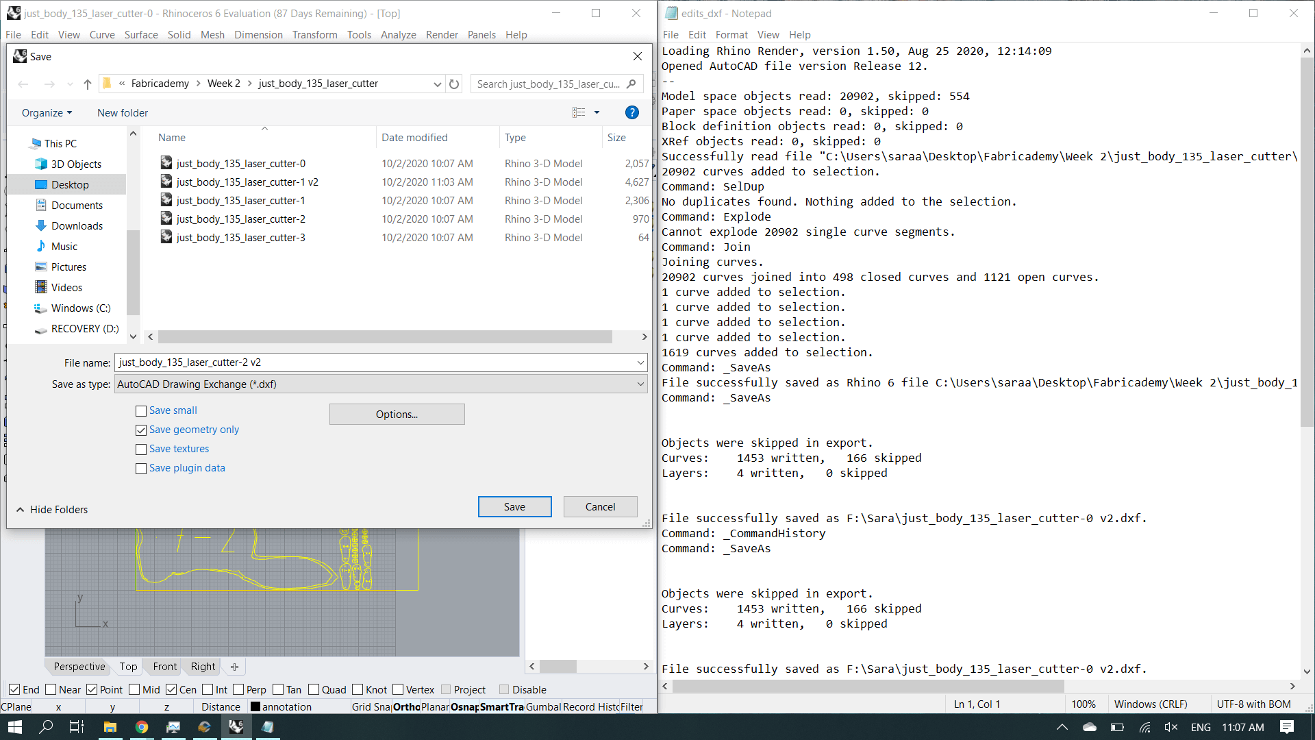
-
Make sure your imported file has the right dimensions. To do that, move it on top of the grid area, which has measurements on the edges. You can check size in the left bar by selecting the object. There you can also scale if needed.
Important tip!
Always make sure the file you imported is placed on top of the grid. Otherwise, when starting the job in the laser cutter, it will fail with "Soft stop", needing to restart it.
-
The software will automatically assign a color to the curves you imported. On the right hand side of the window, you can see a list of layers, each of them with a different color. This is a way to indicate different settings for the laser cutter depending on the part of the drawing. For instance, maybe you'd like some of the lines in the drawing to cut the material, whereas other parts of the drawing should result in engraving. You can select lines by clicking (shift click to select more than one) and then press the desired color at the bottom bar.
-
Once the drawing has the desired distinction of colors, you can set the parameters of the laser cutter on the right hand side. The main parameters are:
- Speed: the velocity with which the laser head will move through the path of your drawing.
- Power: the intensity of the laser.
These parameters vary depending on the material you want to use. It is best to do swatches to test a range of these parameters using a simple shape like a 1cm square. For the cardboard I used on the assignment, I used:
Material Mode Speed Power 3mm thick cardboard Engrave 400 20 3mm thick cardboard Cut 100 50 However, I ended up tuning the laser power in the laser cutter itself to get to desired result while my material was being cut. This is not ideal, but it worked.
-
Take into account that the layers on the right hand side can be ordered to indicate priority. This means that the laser cutter will run through the drawing in the order of colors indicated in the layers from top to bottom. It is also possible to disable certain layers in case you'd like the laser cutter to ignore them (output on/off).
- Once your settings are ready, it may be useful to use the function Laser > Simulate to see the order in which the laser cutter is going to go through the path.
- In the software you'll see a blue dot, usually on the top left corner of your drawing. That is the knife origin or anchor. It will be a useful thing to know when you place your material in the laser cutter as I will explain later.
- Since all settings are set by now, you can press "Download" on the right hand side of the screen. A pop up window will appear. If there are elements on the presented list, first delete all, then press "Download current". The computer will send the file to the laser cutter. Once this is done you can move on to the laser cutter.
- Place your material in the laser cutter bed, making sure it is flat agains the bed. You can use tape or weights if needed. Be careful with the placement of the weights so that the laser head doesn't collide with them.
- Once your material is in place, you need to tell the machine where should it start the job. For that, use the arrow buttons on the machine panel to move the head to the desired location. Once you're satisfied, press Esc > Anchor > Enter. So now you've told the laser cutter that the blue dot on the software that we introduced before is on that location.
- Now you can press Test to check the outline of the laser cutting job. The laser head will move, so be careful that there are no obstacles. This way you can check if the drawing fits in your material, and where to put weights if needed to avoid collisions.
- After this, we can calibrate the height of the bed with respect to the laser head. This is important to have good focus of the laser, which means sharper and more precise lines. For that, take the calibration tool that is on top of the laser cutter (a piece of wood marked as such). Place it between the laser cutter head and the bed with your material still there. The wood piece should fit tight. If it is too loose or too tight, bring the bed up or down using the arrows on the right side of the control panel.
- Finally, you are ready to laser cut!
- Close the lid of the laser cutter
- Turn on the air extractor placed below the computer, and wait fot the tick mark light to be green.
- Turn on the laser in the laser cutter (black knob on the top left of the control panel).
- Press Start (green button on the control panel).
- Remain with the laser cutter all the way through the job and check whether the material is cut or engraved as intended.
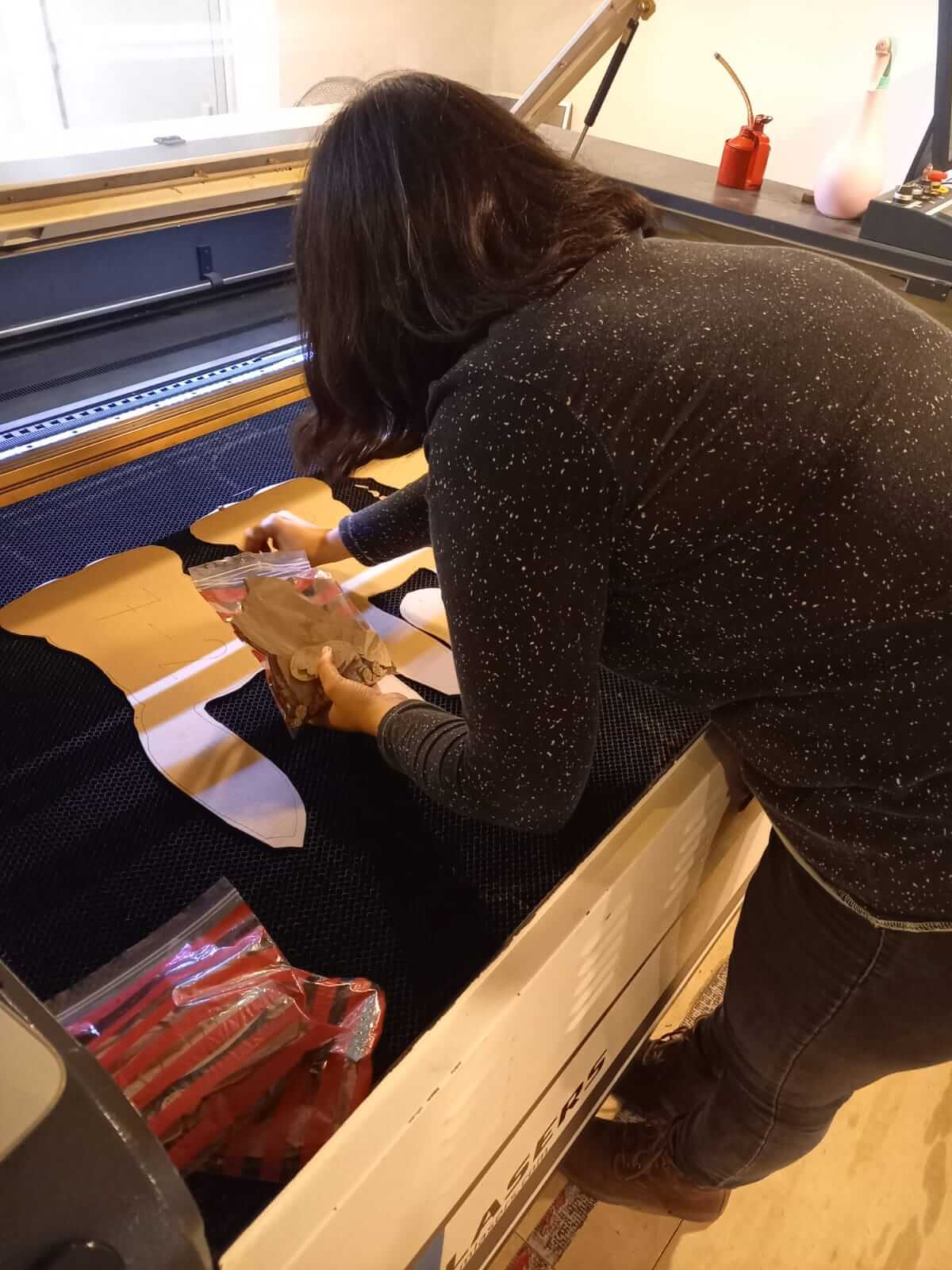
Assembling
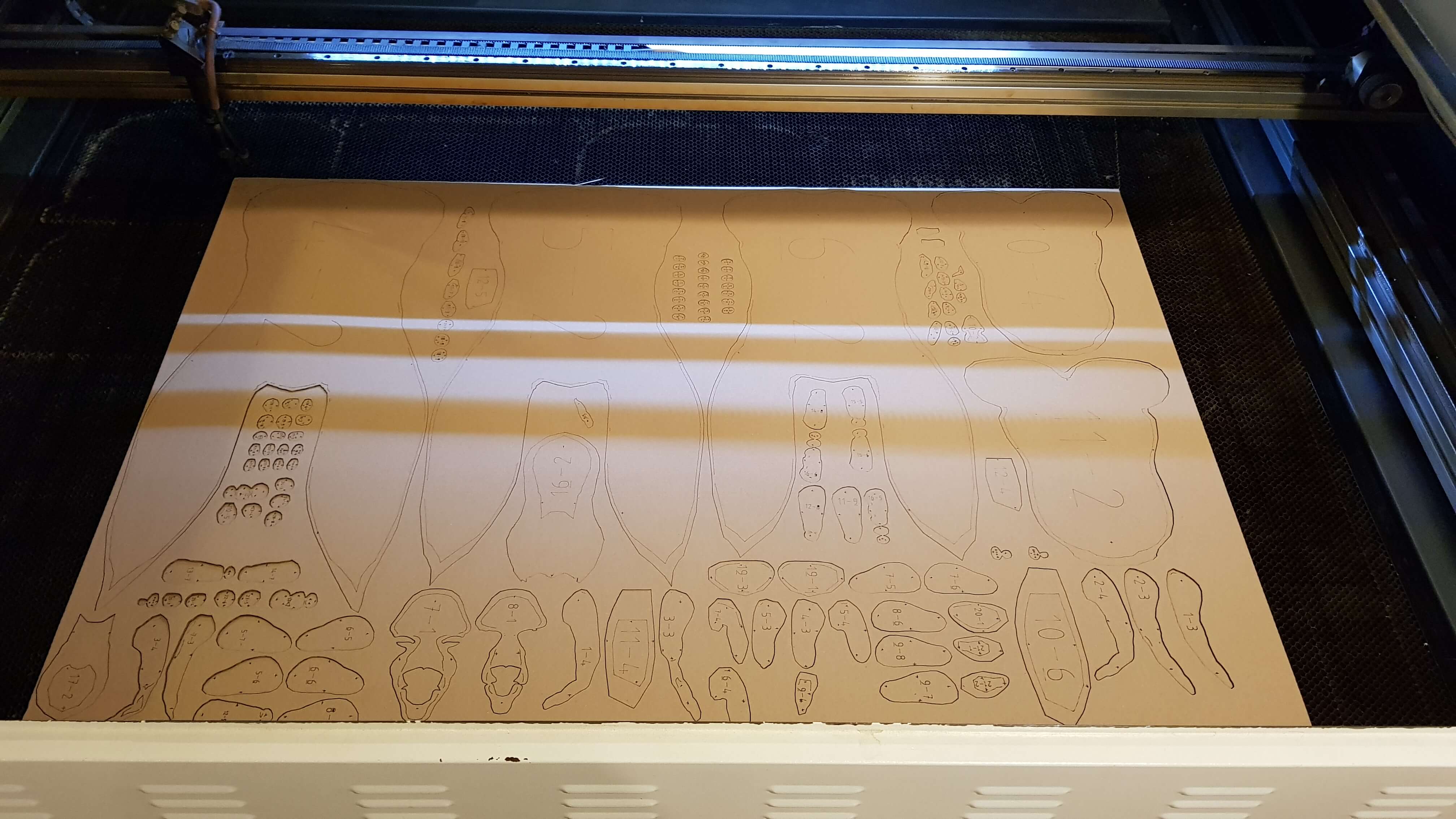
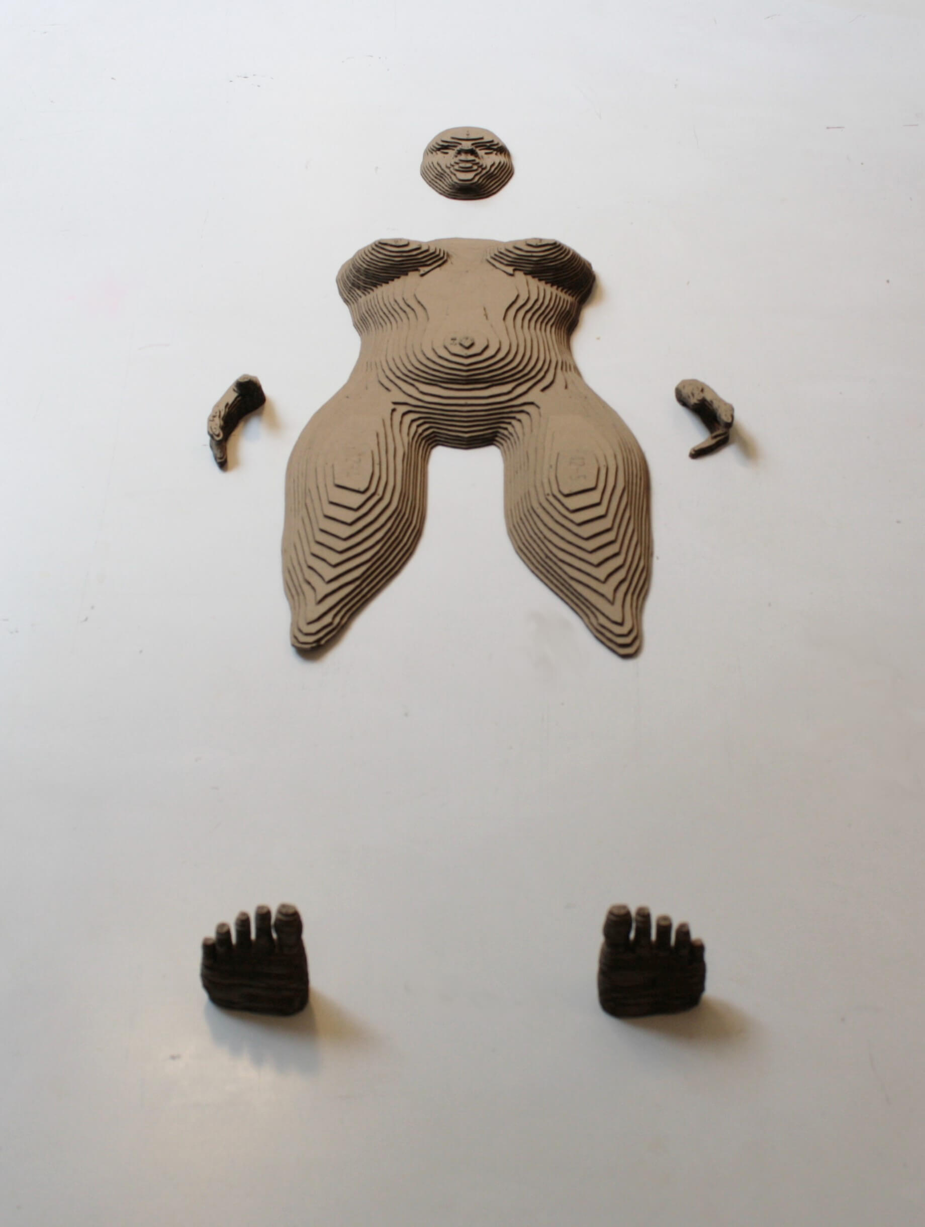
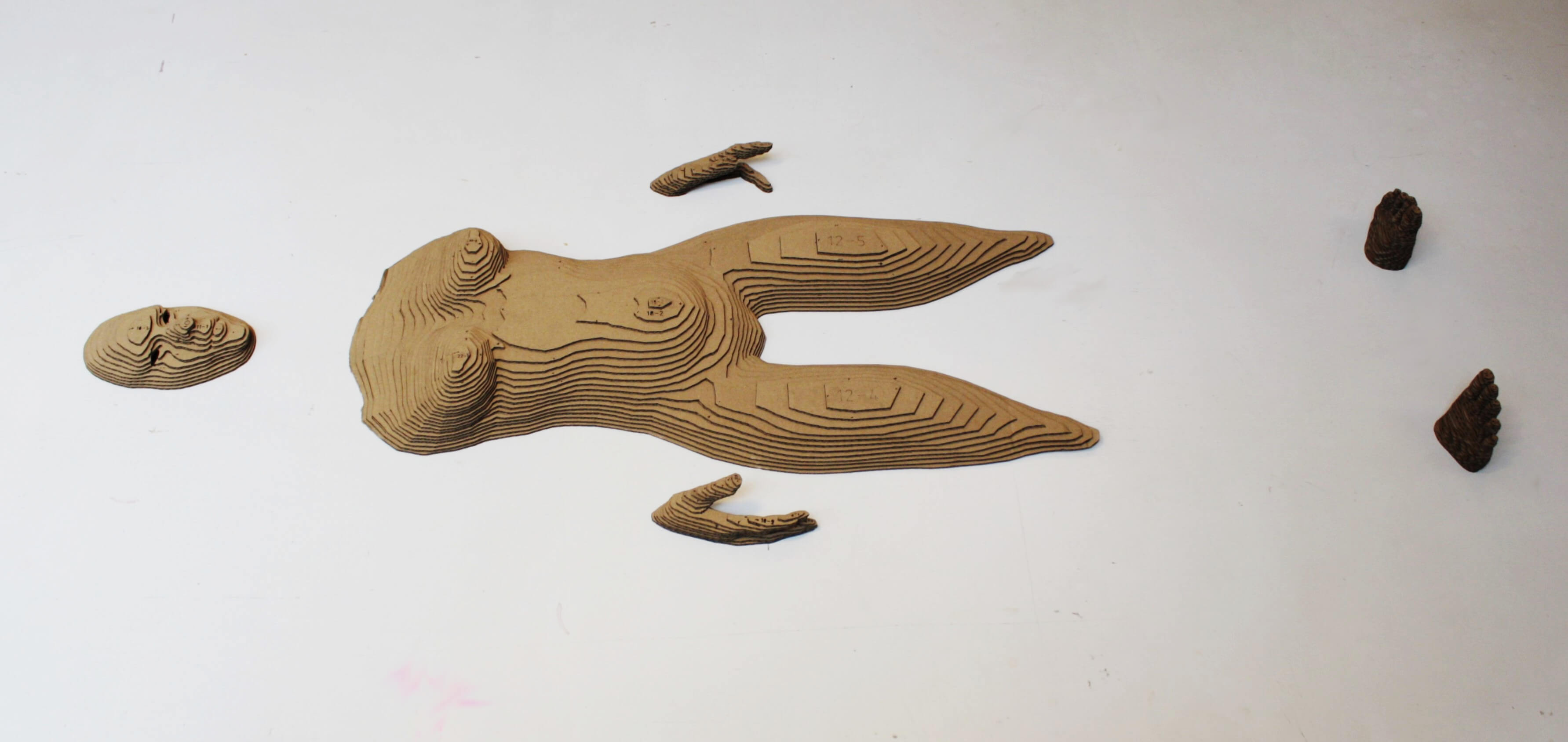
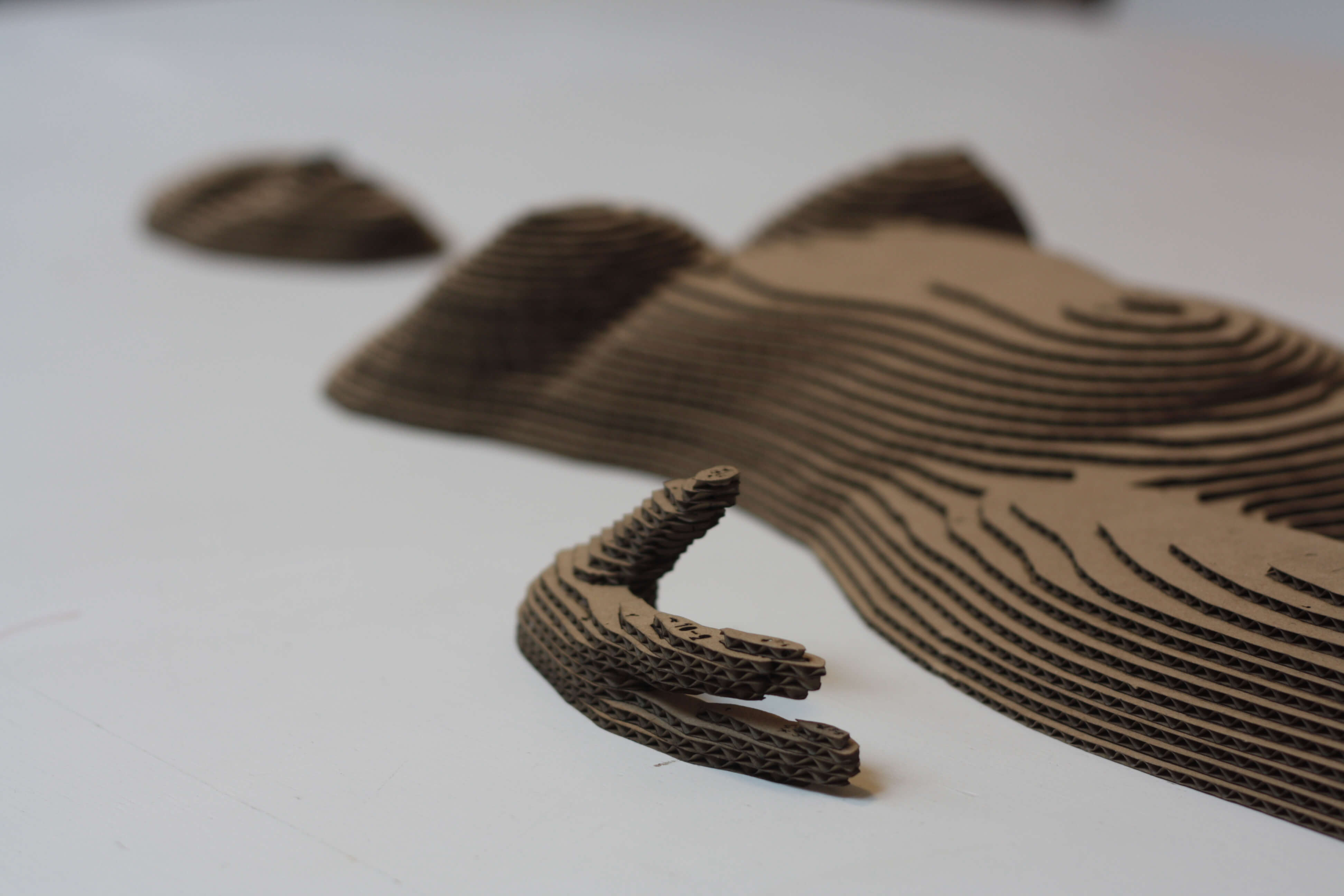
My final assignment consisted on several pieces of cardboard arranged in layers. To make the assembly process easier, I packed the pieces coming out of the laser cutter in different bags depending on their layer number. That way it was easier to find the right part when putting it all together.
I tried different glues to put together the parts. I found out that a common glue stick works better than other more fancy options like glue spray.
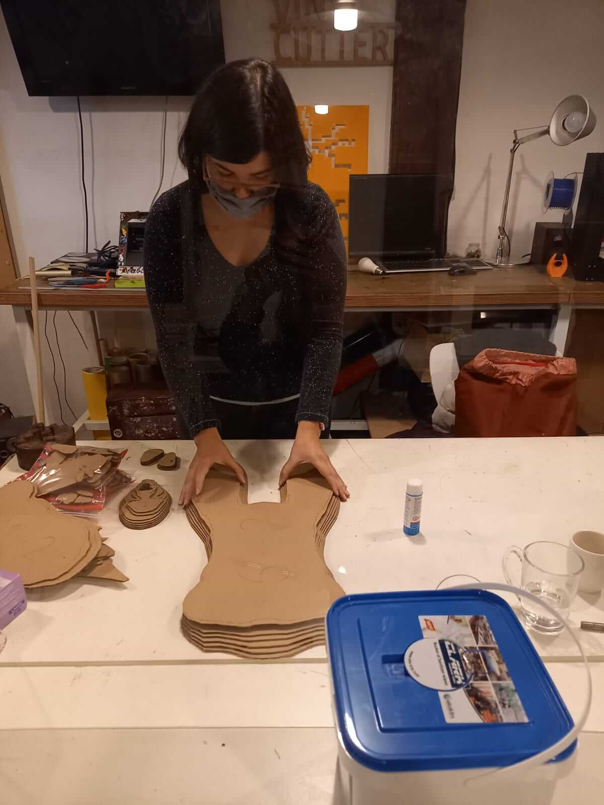
The laser cutter makes the edges of the cardboard burn. This stains when you touch it, which means my finger tips ended out quite dirty, and I had to be careful not to stain the pieces while assembling them.