Digital bodies
Ideation & Inspiration
For this week's project, I immediately thought of 3d-scanning a hand and then building the form from stacked acrylic layers. I enjoy experimenting with how different materials interact with light, so I thought that shining light through the layered form, either from a hollow interior or up through the bottom edges of the material, could produce interesting lighting effects. My second thought was that stacked layers would require a large quantity of acrylic, a material that I try not to overuse, so I probably wouldn't move forward with the concept. Stacking opaque materials would prevent light from passing through, so cardboard and plywood would not work either.
As an alternative, I considered radial slices of cardboard or plywood that would leave room for light to shine through, and then wrapping the form in paper maché or fabric as a diffuser. This method would probably work for a simpler form, but for the hand, fingers would be too thin to construct with an interlocking slice system. In trying to figure out what other forms I could work with or even completely different projects to try in the time I had, I realized that I could just build out my transparent stacked layer concept digitally, produce renders as the final output, and then just build a laser-cut version using opaque material to test the process of slicing and stacking layers.
Inspiration
I looked for inspiration around using the hand as a lamp, as well as stacking layers of material to build up a human form. While I didn't initially find examples of forms build from stacked layers, I did see the opposite, where cutouts (negative space) or embedded objects in the layers stack to create a body inside a block.
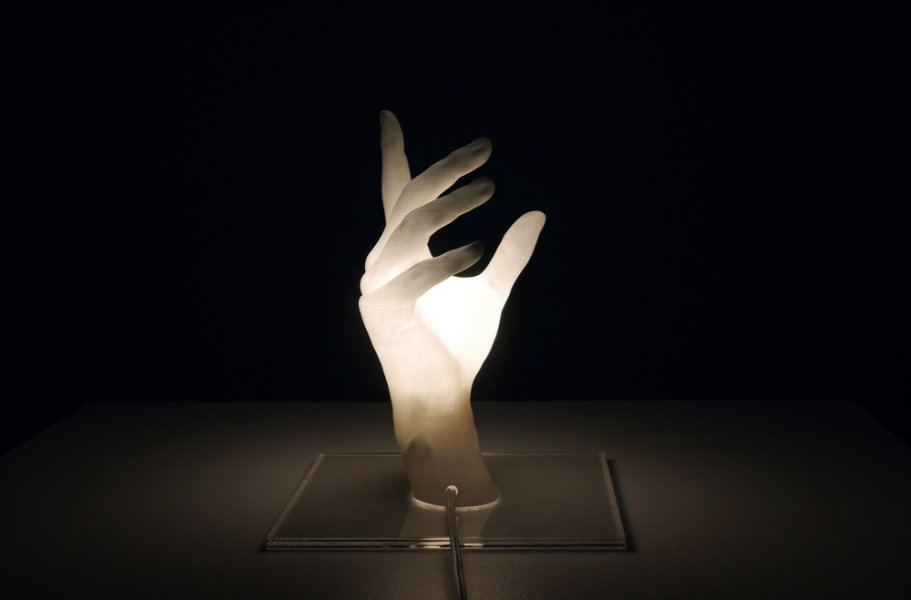
'You Light Me Up' Lamp (credit: Jiwon Jun, 2015)
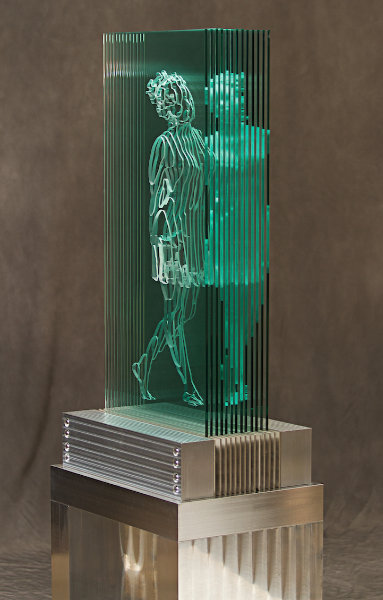
'Siren' stacked glass figure (credit: Jed Malitz)
'Psychogeographies' Layered Resin Sculptures (credit: Dustin Yellin, 2022)
Tools
- 3D scanning with PolyCam
- Modeling and mesh editing with Blender
- Human generation with MPFB
- Model slicing with Slicer for Fusion360
- Vector editing with Affinity Designer 2
- Laser cutting with xTool Studio & xTool P3 laser cutter
3D Scan Exprimentation
Our lab was still being set up and a lot of tools were not yet available, including 3d-scanning, so our local team started out experimenting with smartphone apps that used either the camera (photogrammetry) and/or iPhone pro model LiDAR to generate 3d scans. Polycam seemed to be the most reliable at recognizing an object at all, but our scan results were inconsistent. Scanning Kim Ducharme's torso worked surprisingly well, while smaller objects were missing sections or got cut off.
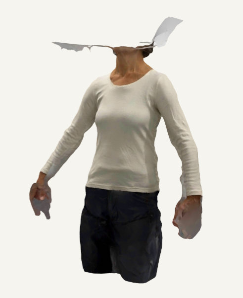
Usable scan of Kim's torso
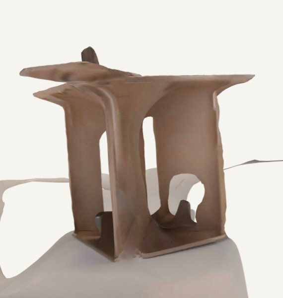
Curved inner corners in failed object scan
Polycam, like most of the apps available, is a paid service, but we tried to stick to the limits of the free version as much as possible. While attempting to figure out whether LiDAR was being used, Pam Intun enabled the paid trial with more features, after which we discovered that LiDAR was restricted to room scanning and was never used for object scans.
Tutorials
As part of this week, we followed Rico Kanthatham's Blender tutorials to generate a model of a human using MPFB.
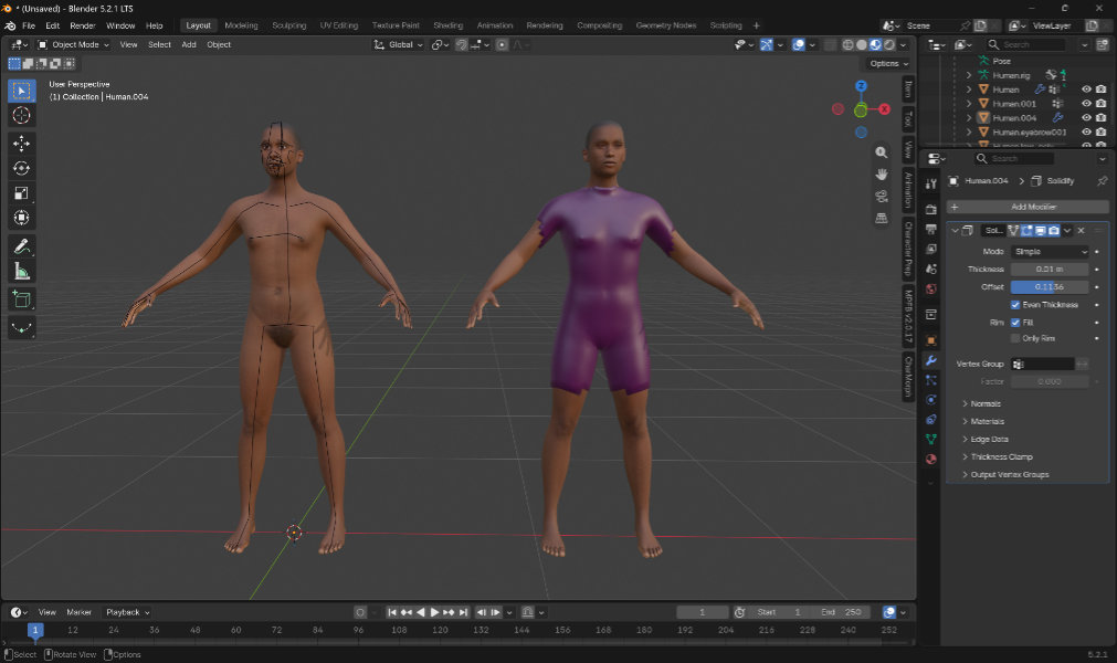
We also had an AI workflow tutorial, from which I jotted down a few personal notes, including a prompt structure for editing images.
"Transform this human figure into [material/system/hybrid]. Keep [pose, face, silhouette, camera angle] unchanged. Emphasize [surface qualities, joints, texture]. Remove background." (Asli Aydin Aksan, 2026)
Hand Lamp Process
Initial Processing
I moved forward with the concept of a lighting a stacked acrylic hand digitally while building a laser-cut prototype from opaque material. To simplify the process, I downloaded a hand model1 rather than using a scan, and began by processing the mesh to remove rigging, scale to rough size, and create a flat base.
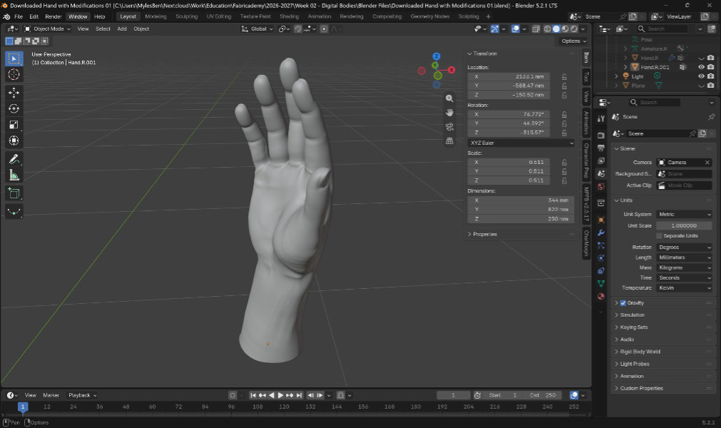
In Slicer for Fusion 360, I sliced my hand model both for 4.8mm foamcore and 2.5mm acrylic, the former being for laser-cutting and the latter to import back into Blender for further processing. I found that, even with dowel holes disabled, the software produced files with small holes, so I had to enable dowel holes and then manually remove them one-by-one to get prevent the holes from being generated.
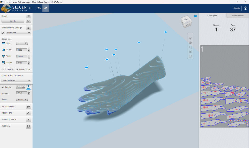
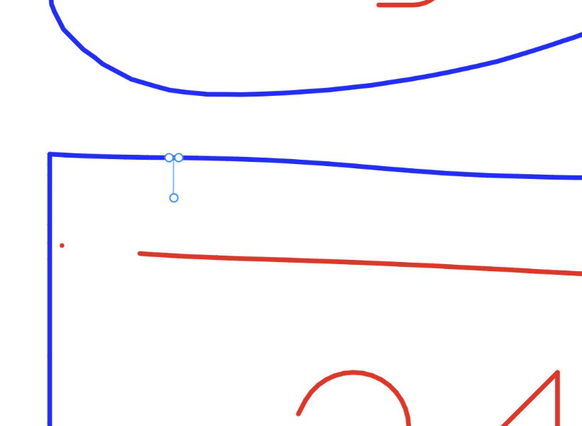
I used Affinity Designer 2 to edit the dxf exports from Slicer from Fusion360, primarily to better nest the parts for efficient material use when cutting. Rather than being full curves/paths, each shape in the initial dxfs was made up of small, disjointed lines, which made it more difficult to move parts around. Rhino has the ability to select many objects and join curves that touch, but in Illustrator and Affinity Designer, the join tool connects all curves, whether they are already touching or not. For some files, Anastasia Pistofidou ran the join command in Rhino, while for others, I carefully selected parts to avoid losing sections.
Foamcore Woes
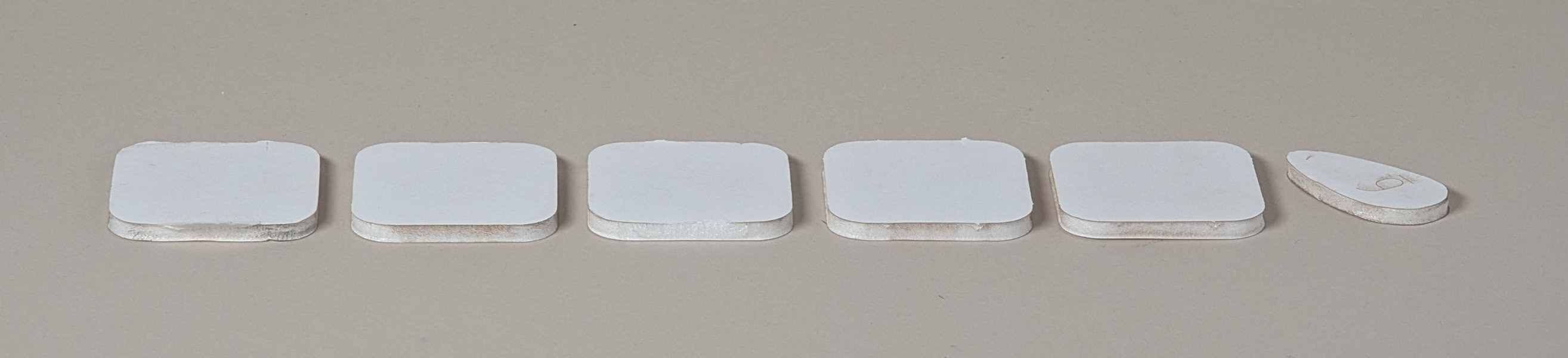
Our node didn't yet have laser-cutting parameters for foamcore, so I worked with shop staff to run settings swatch tests and work towards a working profile. This proved to be incredibly difficult, as the foam core of the foamcore more easily melted while not cutting through. The material would even cut well along the y-axis but fail to cut properly along the x-axis, which could have indicated an issue with machine's mirror system. Eventually, we settled on a two pass cut which left only small tabs of the backing paper uncut, but when I went to cut a layer of my hand model, the piece cut through on the first pass, shifted, and then melted/burned on the second pass.
Creating Digital Acrylic
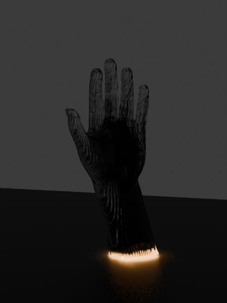
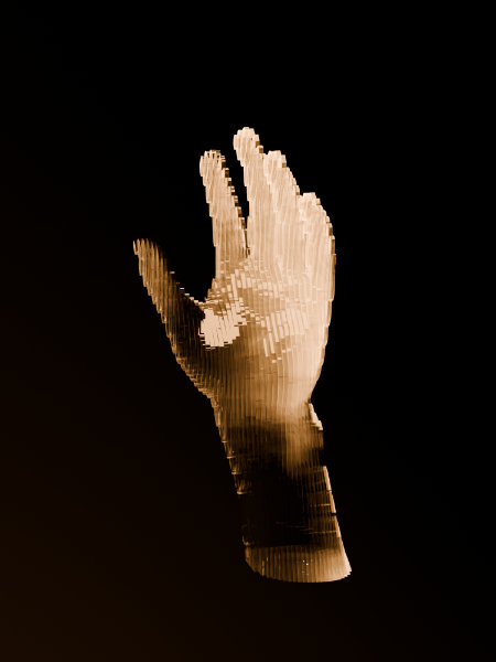
My intention with this project was to bring my sliced hand model back into Blender and use the digital file to experiment with lighting the acrylic up from the bottom edge. I gathered a few tutorials and began configuring material properties2, but when I went to render, I found that light didn't pass well through the edges of the material and instead needed to go through the larger faces. I played around with the settings and rendered a few variants, but I was unable to light the material as I would have liked.
Edge-lit acrylic render
Side-lit acrylic render
In an forum post about creating acrylic plastics in Blender3, it was mentioned that the free rendering engine LuxCoreRender is a better option than the cycles for accurate lighting and transparent materials, as it has the ability to render caustics. While I didn't get to following tutorials or working with the extension, I anticipate that I will be learning more about LuxCoreRender during this program, as I intend to work with transparent materials and would like to be able to include photorealistic renders in my portfolio.
Acrylic Partial Hand
After the foamcore failures, I needed to produce at least a partial physical model quickly. I realized that, if I cut only a small section of the full acrylic hand, I could choose an area where dowel holes would run through every layer and then tie the pieces together through the holes instead of using acrylic solvent for assembly.
Tolerancing
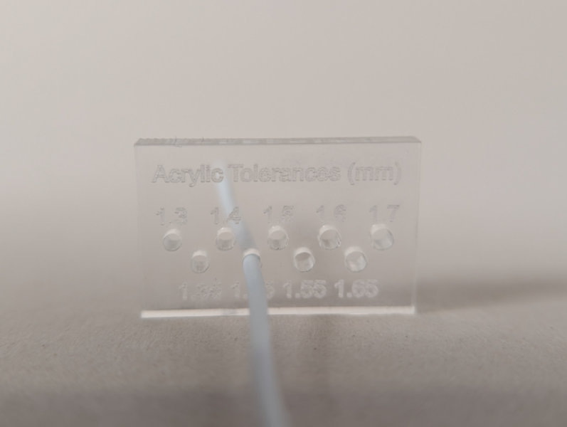
To start, I tested hole tolerances to know what size dowel holes to include in a new sliced model. I found some rubber-coated wire in the lab that I could use, and it measured in at 1.6mm diameter. In Affinity Designer, I made a quick tolerance tester with hole sizes decreasing in 0.05mm increments. I cut and etched (scored) the piece out of transparent 3mm (2.5mm) acrylic using the xTool default settings, as I suspected that clear acrylic might cut slightly differently from the opaque materials for which we had samples. I didn't expect there to be much of a difference in fit for 0.05mm difference in hole size, so I was surprised to find that 1.45mm was the best fit, with 1.4mm much to tight and 1.5mm quite loose.
Laser Parameters: 3mm clear acrylic on xTool P3
- Cut: 80% power, 25mm/s speed
- Etch/score: 15% power, 200mm/s speed
Model Preparation
Instead of reusing my original sliced hand file and only cutting a few layers, I decided to go back into Blender and export a model of only the section I wanted to work with. I moved planes around to block off an area of interest and then replaced them with a cube to encapsulate section. Toggling x-ray mode on allowed me to see the hand section inside the cube. I set the cube's y-dimension to be a multiple of the acrylic's 2.5mm thickness, that way it would evenly divide into layers.
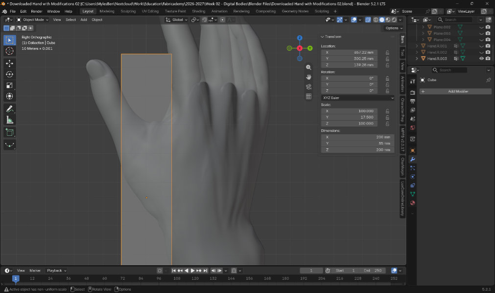
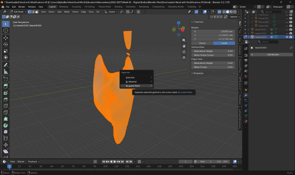
I added a boolean intersection modifier to my hand mesh using the cube as a tool object, which left only the section of the hand that had been encapsulated in the cube. After applying the modifier, I could then split by loose parts in edit mode to separate two bits of hand that we detached from the rest of the section.
Slicing
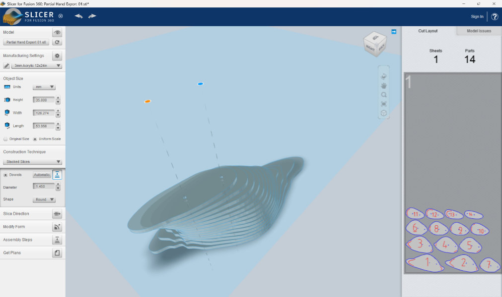
In Slicer for Fusion360, I imported my hand section and set the dimension for the layer height. I selected my material and chose the stacked slices construction technique. To add dowel holes, I first enabled dowel holes and set the diameter to my tested 1.45mm. This only generated a single hole, so clicked the layer/preview button to the right of the dowel checkbox to view the hole placement. I could then click and drag the dowel hole to where I wanted. I then added a second hole my clicking on the blue plane and then dragging the hole to a better location, rotating the model to make sure it passed through each layer without getting to close to an edge. Once I was happy with how the slicing looked, I exported a dxf.
Fixing the DXF
The cut layouts produced by Slicer for Fusion360 are not very material efficient, so I brought the file into Affinity Designer to nest the parts better. Without joining all the tiny lines first in Rhino, the nesting process involved selecting parts, moving them to a blank space so I could easily select them again without catching other lines by accident, then placing each part manually.
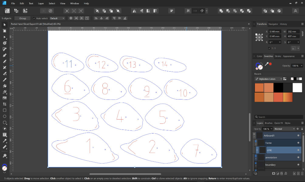
Original layout
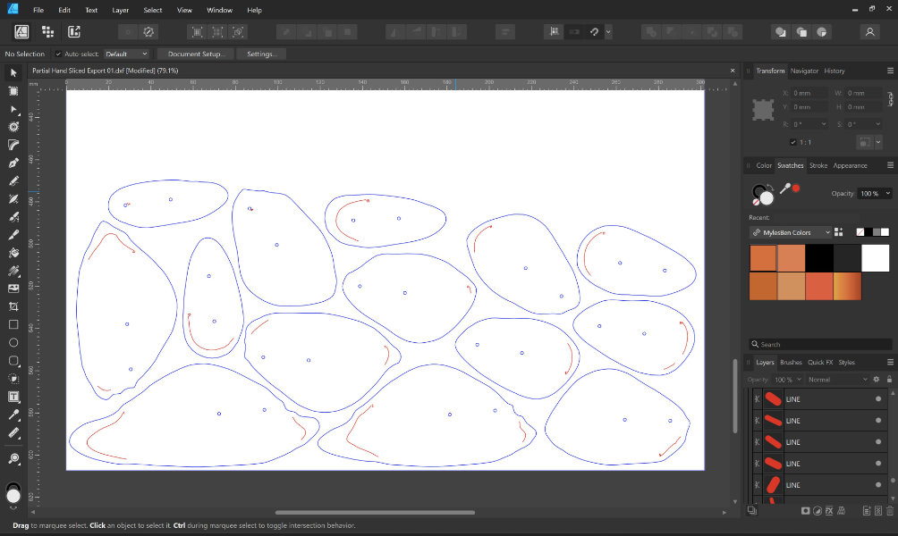
Nested layout
Since I was working with transparent material and didn't want to see the large numbers etched into the faces of my parts, I shrank the labels to 1mm height and placed them in inconspicuous areas, either at the end of an etched alignment curve or next to a dowel hole.
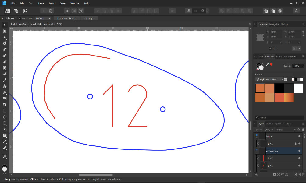
Original label
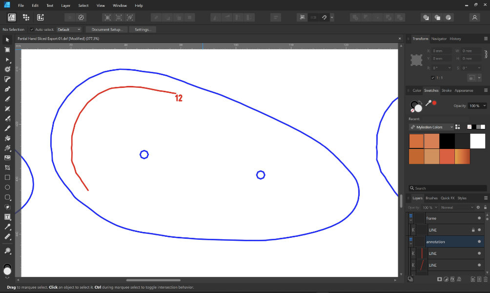
1mm label
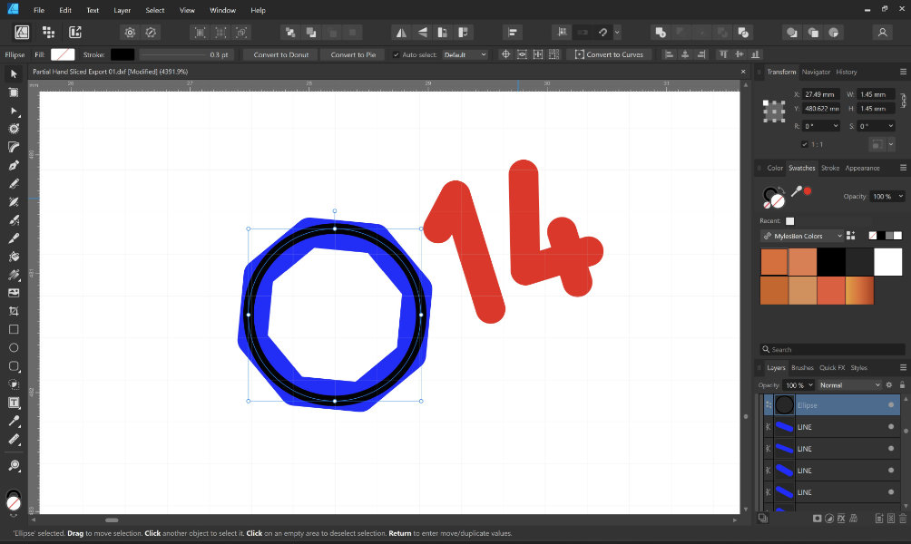
I saw that the dowel holes were hexagons instead of circles and suspected that this would change the tolerances from what I had initially tested, so I cut a single layer to test and the wire didn't fit through. To match my tolerance testing, I joined the lines in each octagon to get a complete shape placed a 1.45mm circle at its center, then deleted the octagon.
Cutting & Assembly
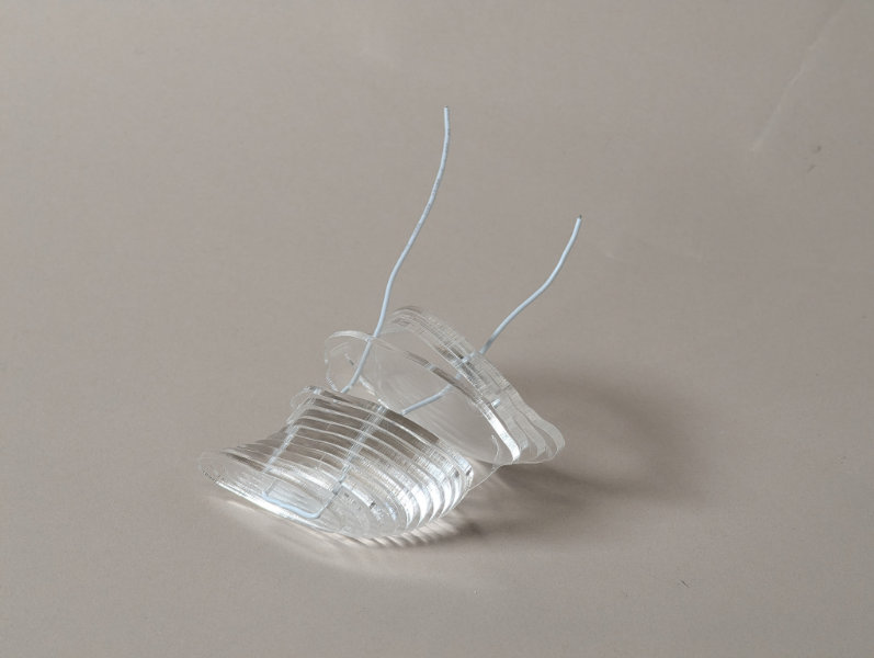
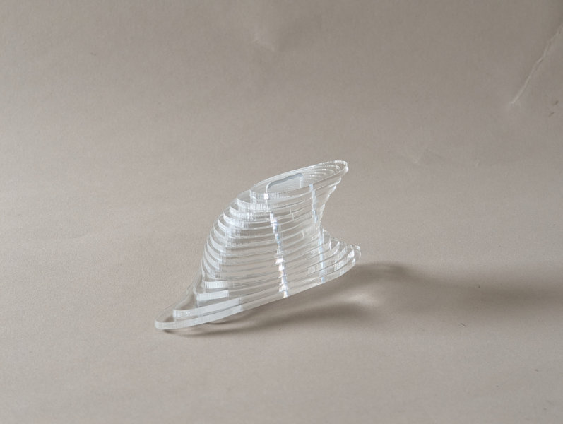
I cut all of my layers using the same laser cutting settings as my tolerance testing, stacked the pieces by number, and threaded the wire through. Because the laser produces a tapered cut, as it's only focused on the top surface of the material, the wire only easily fit through the acrylic pieces in one direction. Once everything was in place, I twisted the wire on the bottom of the piece to secure it.
Results
Assembled prototype
Bottom-lit
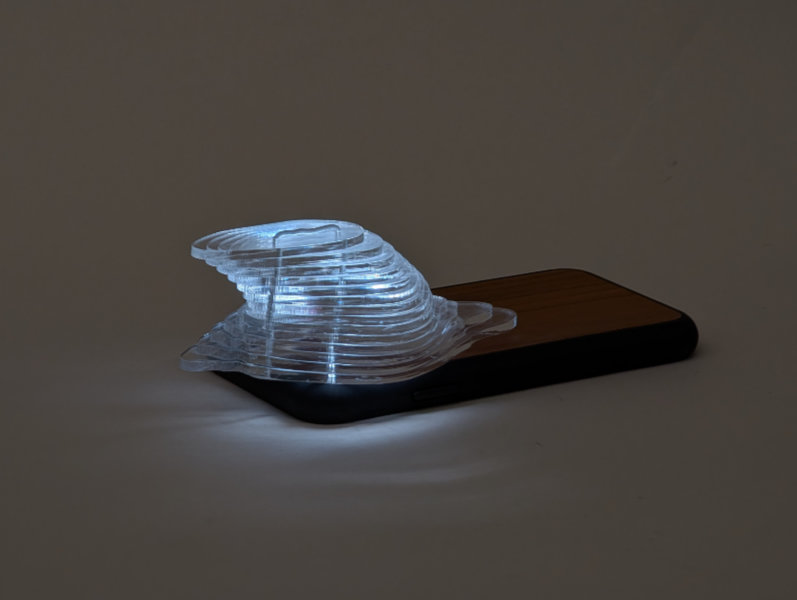
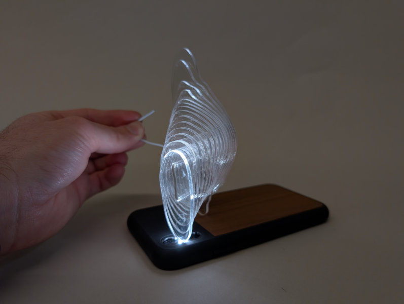
Although I rushed this prototype and didn't even clean the layers before assembly, I really do enjoy looking at the final result and hope to make a full form using this technique at some point. The section that I actually build lacks the aligned edges need to truly see how an edge-lit piece would look, but just lighting a single edge, gives some idea for how light transmits through the material.
Reflection & Thinking Towards the Future
Again, this was not a great week for me. I really do need to do the simplest projects possible and figure out how to speed up documentation so it doesn't slow down project work. While I enjoy helping others and working out kinks in the lab, I just don't know that I can keep it up. Some major learning for me this week was to trust my engineering and design intuition rather than second-guessing myself, as I could have avoided a lot of time-sinks by doing so.
Fabrication files & References
File: Hand with flattened base - working Blender file File: Partial hand cut file for 2.5mm material