5. E-textiles
Introduction
This week we were introduced to the electronic world. What a vast world !
There are some basic information to note about electricity :
- Current : the "flow" of electrons. We mesure the intensity of current : it's the number of electrons/second passing through one point of the circuit. The unity of mesure is Ampere and the symbol I.
- Voltage : the electrical pressure, the "force" between two points in the circuit. The unity of mesure is Volt and the symbol is V.
- Resistance : an opposition force to the circuit. We add resistor to "balance" the circuit. If we increase the value of the resistor, the intensity of the current decreases. The unity of mesure is Ohm and the symbol is Ω.
These three components are associated as following :
This is the Ohm law: V = I x R
Important points to note :
- the electrons go as fast as possible
- there are no loss in the circuit
- the circuit is a system
- the circuit is a closed loop !
Material
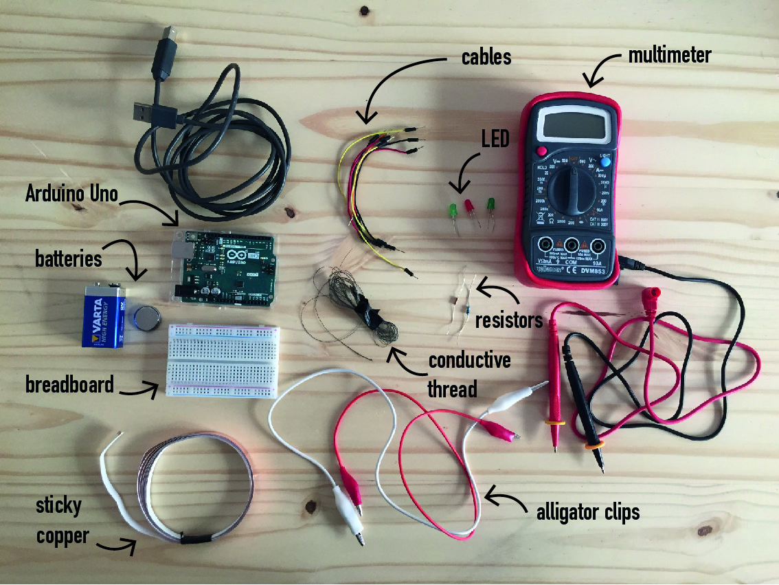
We use the multimeter to mesure the voltage and the resistance but also to check the conductivity of an element or to check the conductivity between two points of the circuit. If the circuit is not working, multimeter is a great help to understand what is wrong.
The battery is the power source. It causes the movement of the electrons. It's a storage of electrons.
The resistors impede the flow of electrons. It has no orientation !
LEDs belong to the group of diodes. It has an anode (+) and a cathode (-). The forward voltage (Vf) is the optimal voltage and the forward current (If) is the maximum current that you can fix (higher would damage the LED). We can use The Led resistor calculator .
Arduino is a microcontroller. We can integrate it into a circuit and programm it to produce electrical signals.
The breadboard is a physical support to test the circuit.
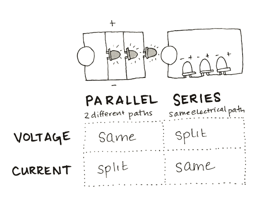
Circuit
There are two kind of circuits, which are serie circuit (same electric path) and parallel circuit (2 different paths). This picture from Lisa Stark's class is a perfect summary :
Digital switch
Digital means 1 or 0, on or off, low or high, open or close -> there are two positions in a switch. I made my first digital switch with copper textile, a conductive material. I coded the Arduino so the light turns on and off depending the position of the switch.
Test with Arduino
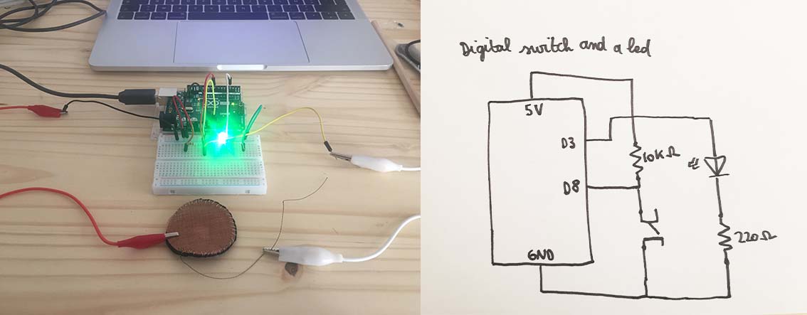
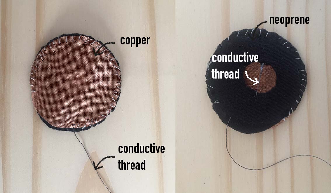
I used 2 pieces of neoprene to make the "sandwich". When the copper touch the conductive thread, it closes the circuit. To make this circuit, I used the code which is in Emma Pareschi's class :
int digital_sensor_pin = 8;     //change the pin, where the sensor is connected?
int digital_sensor_value = 0;
int led_pin = 3; //change the pin of the Led

void setup() {
  // put your setup code here, to run once:
  pinMode(digital_sensor_pin, INPUT);
  Serial.begin(9600);
  // initialize digital pin LED_BUILTIN as an output.
  pinMode(led_pin, OUTPUT);

}

void loop() {
  // put your main code here, to run repeatedly:
  digital_sensor_value = digitalRead(digital_sensor_pin);

  // check if the pushbutton is pressed. If it is, the buttonState is HIGH:
  if(digital_sensor_value == HIGH){
        // turn LED on:
      digitalWrite(led_pin, HIGH);
  } else {
        // turn LED off:
      digitalWrite(led_pin, LOW);    // turn the LED off by making the voltage LOW

  }

}
Test on textile and digital embroiderer
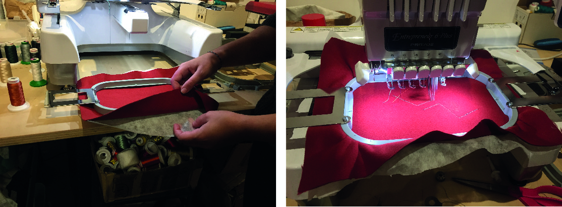
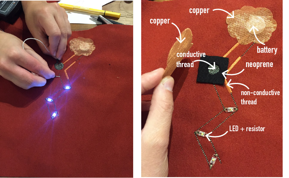
We made a test on textile with Louise, Marie Charlotte and Julie. It was also a nice test to try the digital embroiderer. We used copper and neoprene to make the switch.
We prepared our drawing on PE design II. We first had to chose the size of the canva -> 18x13 cm. To change the setting of the point, we went to the settings : menu -> shapes -> outline -> straight stitch. We used the straight stitch and the zigzag stitch. There are many other ways to embroider. We draw directly on the software but we could also import a vectorial file from Illustrator or Inkskape (to do that, the file format should be in WMF). We used two colors : one for the conductive thread and the other one to the non-conductive thread. Then we uploaded the file in the digital embroiderer, we changed the thread and we "coded" the colors so they could correspond to our threads (conductive and non-conductive). Be careful, conductive thread is very touchy, for instance we had to cut it manually.
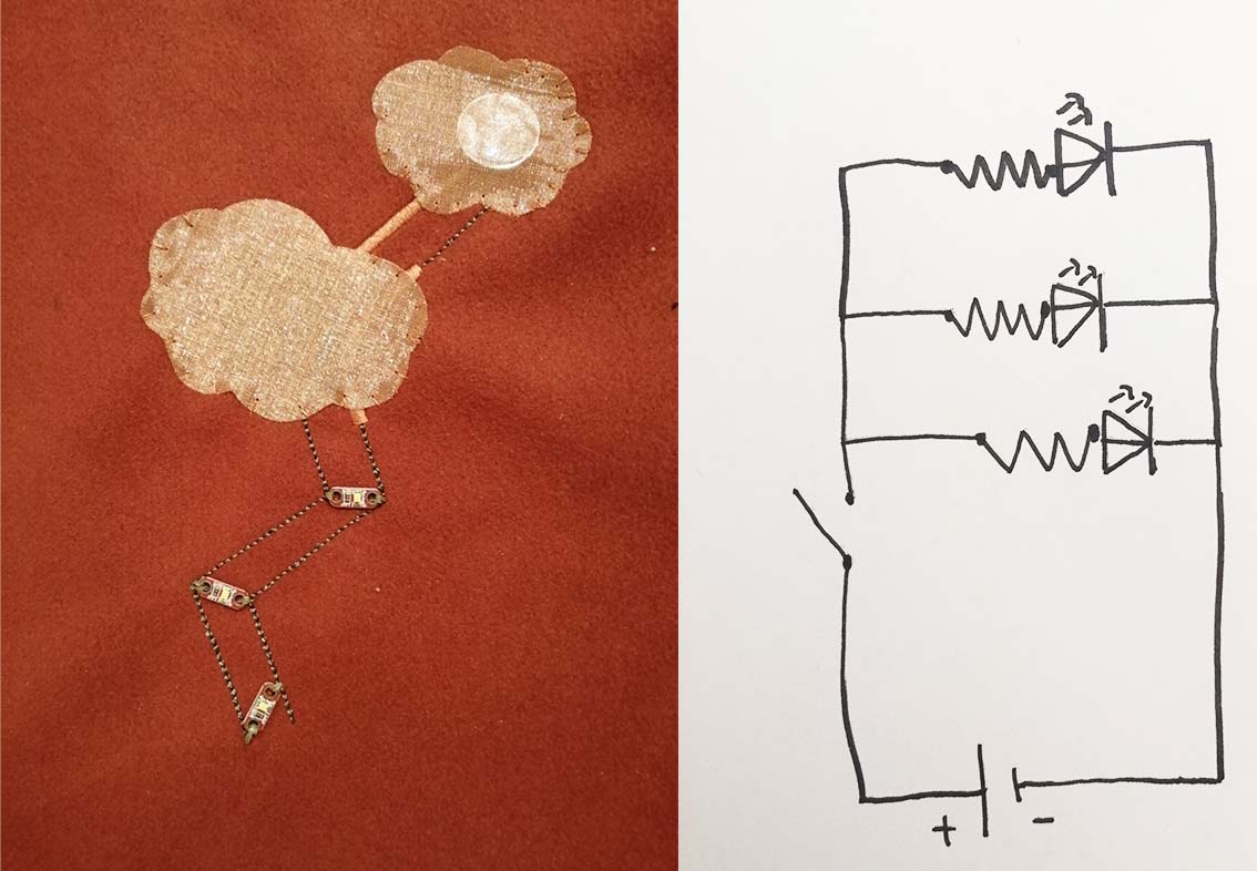
How does it work ?
It's a parallel circuit. The copper cloud touches the positive side of the battery and the conductive thread is isolated from the copper by a non-conductive thread. The digital switch is a "sandwich" made of copper and neoprene.
Analog Sensors
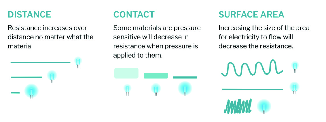
Analog means all values between minimum and maximum. For instance, the brightness of a LED is not only just Low or High but it has many light variations. To create an analog sensor, we can use the resistance property of the materials. This drawing from Lisa Starck's class helps me to understand how resistance changes even if we use the same material. This change of the resistance'value will change the brightness of a LED (for example).
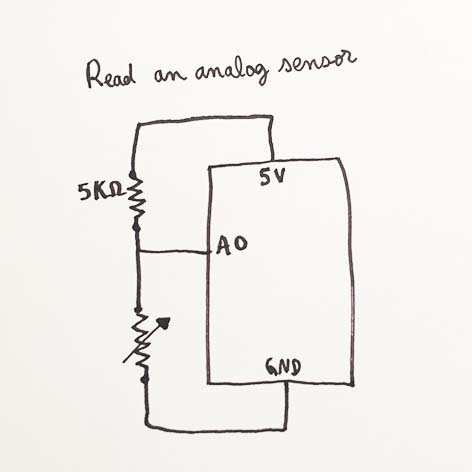
For each sensors, before I did the test with the light in Arduino, I "read" the values, minimum and maximum in Arduino. This is the circuit to read the values :

And the code :
int analog_sensor_pin = A0;   //change the pin, where the sensor is connected?
int analog_sensor_value = 0;

void setup() {
  // put your setup code here, to run once:
  pinMode(analog_sensor_pin, INPUT);
  Serial.begin(9600);

}

void loop() {
  // put your main code here, to run repeatedly:
  analog_sensor_value = analogRead(analog_sensor_pin); //read the Voltage of the pin sensor

  Serial.println(analog_sensor_value); // print the value on the Serial monitor
  delay(100);

}
Velostat
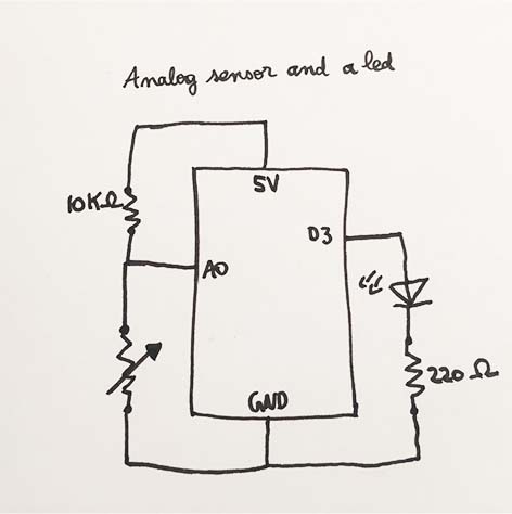
For the next three tests, I used the same circuit and the same code.
The code is :
int analog_sensor_pin = A0;   //change the pin, where the sensor is connected?
int analog_sensor_value = 0;
int led_pin = 3;


void setup() {
  // put your setup code here, to run once:
  pinMode(analog_sensor_pin, INPUT);
  pinMode(led_pin, OUTPUT);
  Serial.begin(9600);
}

void loop() {
  // put your main code here, to run repeatedly:
  analog_sensor_value = analogRead(analog_sensor_pin); //read the Voltage of the pin sensor

  analog_sensor_value = map(analog_sensor_value, 230, 130, 0, 255); //we change the range
  analog_sensor_value = constrain(analog_sensor_value, 0, 255); //we apply the limits

  analogWrite(led_pin, analog_sensor_value);  //we use the mapped value to control the Led
  Serial.println(analog_sensor_value); // print the value on the Serial monitor
  delay(10);

}
I just changed the values that I read with the previous code in this line of code :
analog_sensor_value = map(analog_sensor_value, 230, 130, 0, 255); //we change the range
Velostat contains carbon and it means it's a conductive material. I did the same test as in Emma Pareschi's tutorial but I sewn the velostat in a piece of textile so we could imagine what it'd look like if we integrated it to a textile. One conductive thread is upside and one conductive thread is down the velostat. The more we push on the velostat, the less resistant it is.
Silver elastic textile
This textile is a silver knit conductive fabric. Depending on how streched it is, the value of the resistance changes.
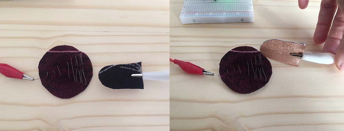
Copper and conductive thread
I made this analog sensor with copper and conductive thread. Conductive thread is not sewn regulary, so when we take the copper part and caress the conductive thread, the copper interacts with the different surfaces of thread. It gives different values of resistance. I sewn conductive thread and copper on velor so it looks like a caress.
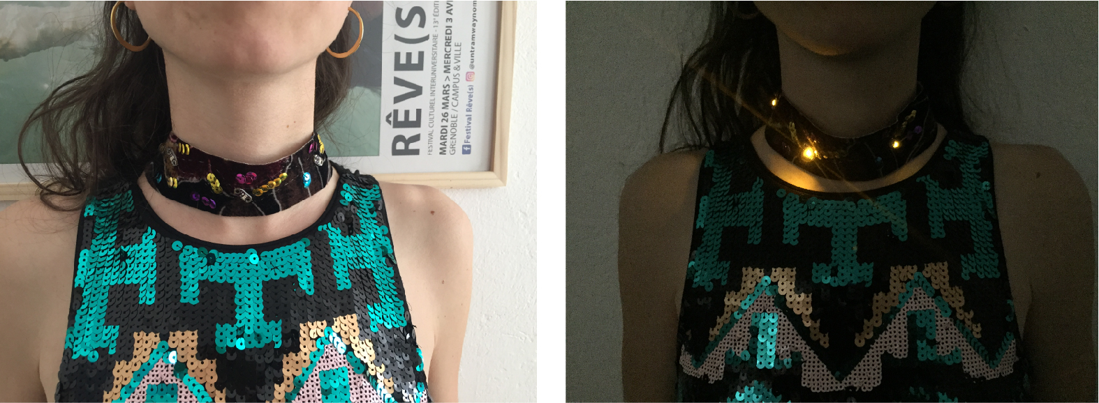
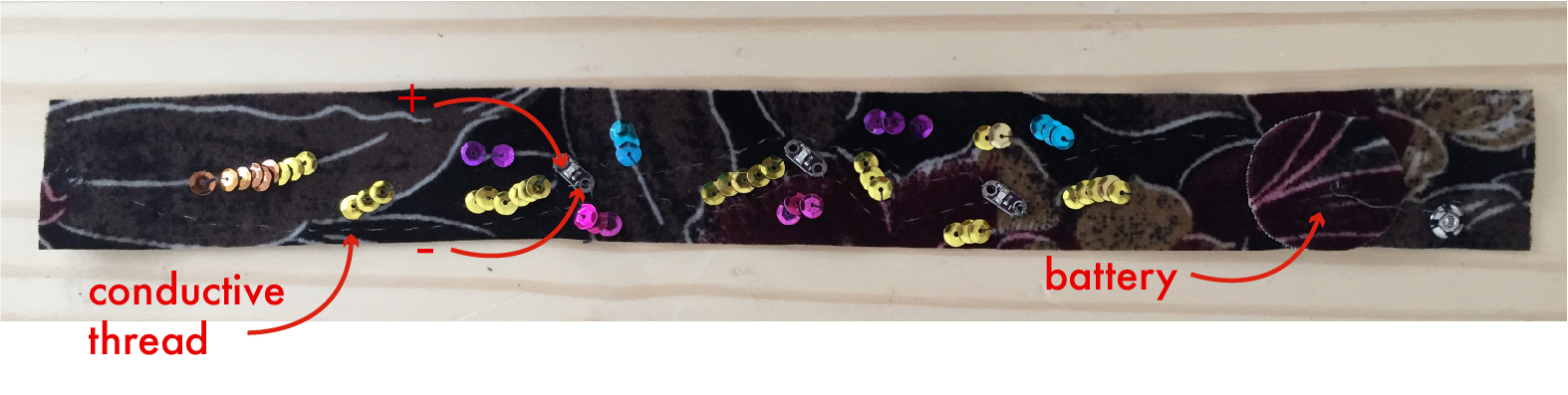
Necklace
I made this necklace with 3 LEDs, conductive thread and a press stud. When the necklace is closed, the circuit is closed and the LEDs turns on.