10. Wearables
This week is the second week of electronic applied to textile.
Emma Pareschi's tutorial Power loads.
Pareschi's tutorial Arduino, Neopixels and sound.
References
This is a thermochromic tapestry that changes colour in response to Wi-Fi signals from Alis Morris.
This dress from Julianna Bass can change colours thanks to an electronic circuit and thermochromic ink.

Jingwen Zhu made My heart on my dress and she explains how it works : The custom-made dress is screen printed with thermochromatic ink and wired with soft circuits and thermal patches. Its patterns and colors transform based on data analyzed from a personal diary app.
Thermochromic ink
We made some tests with thermochromic ink; this ink changes colour depending on the heat.
Preparation of the ink
We prepared the ink with pigments that we mixed with wood glue. We were not sure about the wood glue but it actually worked very well. We made 4 tests :
| Pigments | |||
|---|---|---|---|
| test 1 | test 2 | test 3 | test 4 |
| woog glue | 15g | 10,8g | 13,6g |
| pigments | 0,5g | 0,1g | 0,04g |
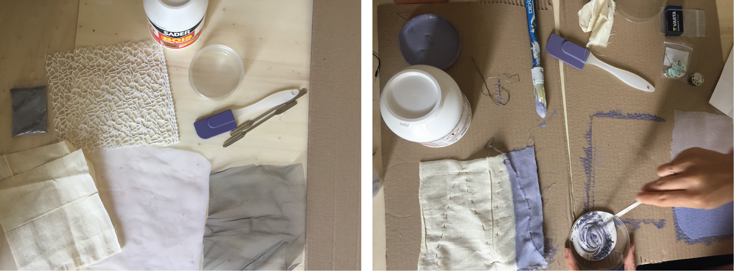 Preparing the samples and mixing the pigments with the glue
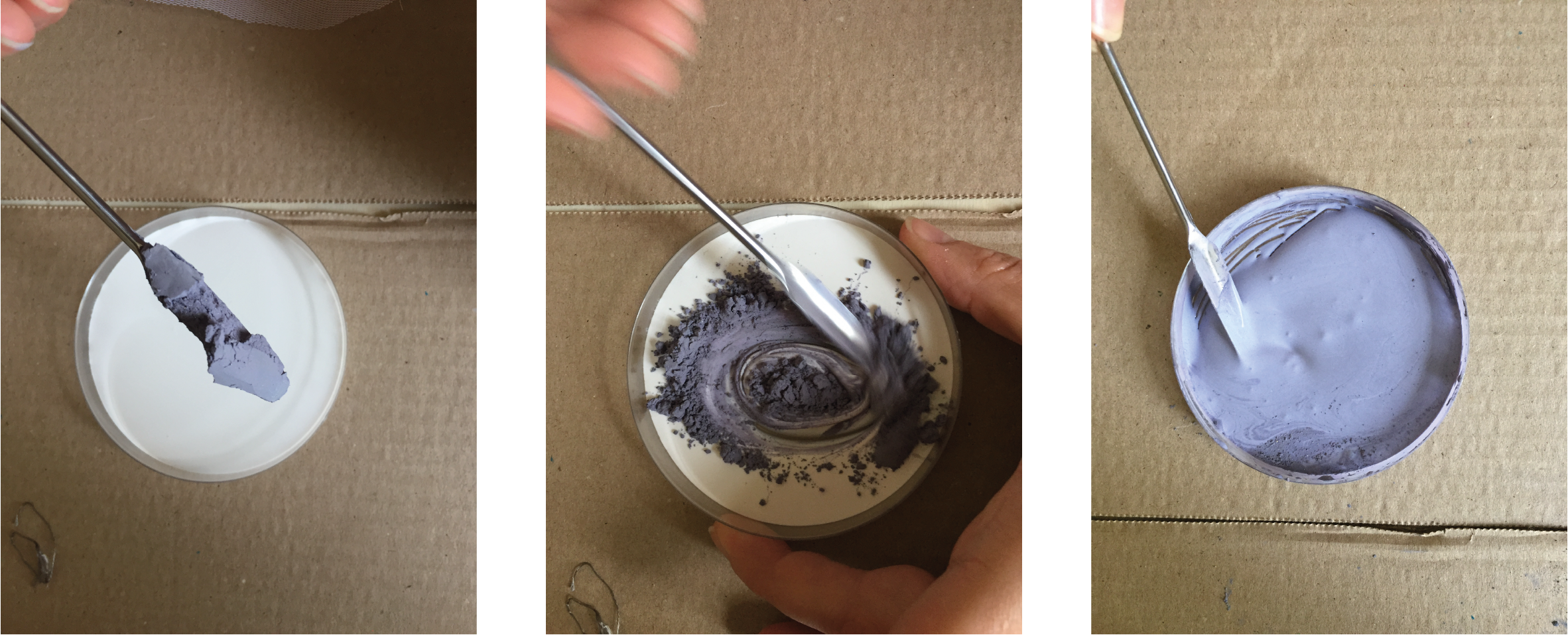 The mixture should become smooth
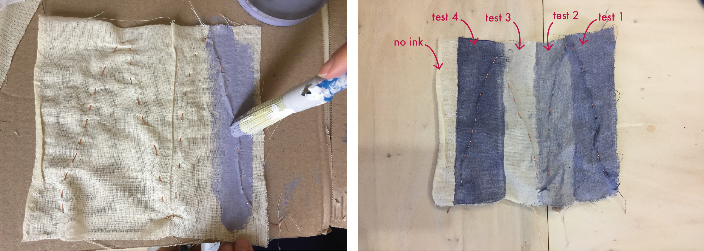 Printing the fabric with our different mixtures
Note : the fabric becomes harder and heavier.
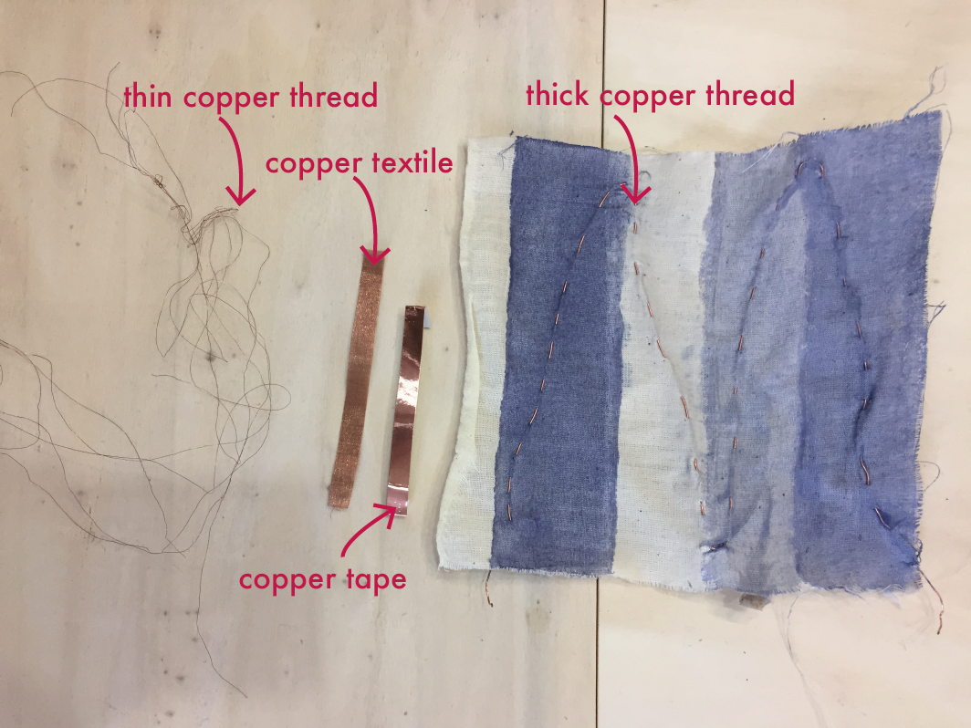
With conductive thread
We sewed conductive thread on textile and paper.
This is the test on paper :
This is the test on textile :
We discovered that it worked better with the test 4, the one with more pigments. This is another test on textile ; the conductive thread is sewn behind the lace :
With copper
We made some tests with copper. It didn't work for any of them, maybe because the copper is too conductive and doesn't heat up enough. This is our test :
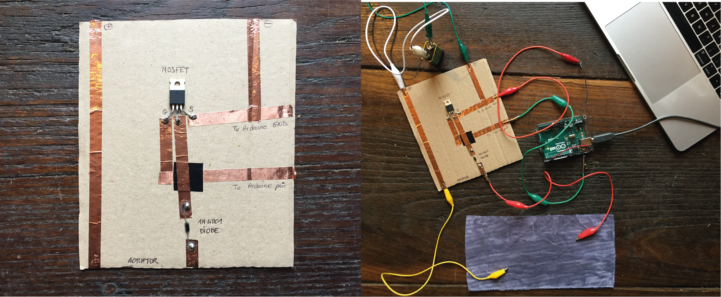
Transistor
We needed to make a circuit with a transistor.
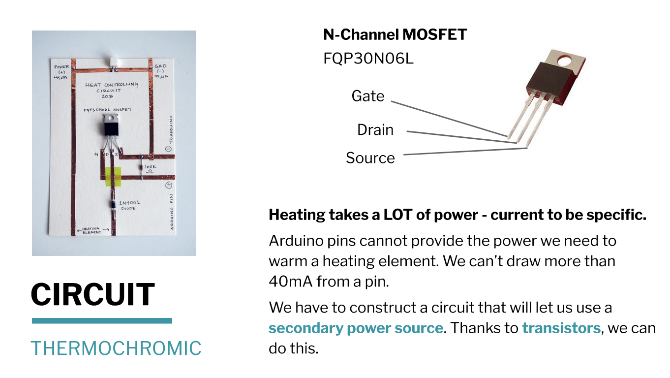 Slide is from Lisa Stark'course
This is a Arduino sketch to heat up an element that I found on Patty Jansen's page.
void setup() {
  // put your setup code here, to run once:
pinMode(3, OUTPUT);
Serial.begin(9600);
}

void loop() {
  // put your main code here, to run repeatedly:
analogWrite(3,500);
Serial.println("On");
delay(2000);
analogWrite(9,0);
Serial.println("Off");
delay(2000);
}
Neopixel
We followed Emma Pareschi's tutorial. In this circuit, we were careful that none of the cables touch each other, this is why we put tape on it. The sketches are from Emma Pareschi's class. First, we uploaded the neopixel library in Arduino. This is the circuit we made :
![]()
There are some examples of the class :
Rainbow neopixel
Nice rainbow colours.
Arduino sketch :
#include <Adafruit_NeoPixel.h>

#define LED_PIN    6

// How many NeoPixels are attached to the Arduino?
#define LED_COUNT 4

// Declare our NeoPixel strip object:
Adafruit_NeoPixel strip(LED_COUNT, LED_PIN, NEO_GRB + NEO_KHZ800);

uint32_t off = strip.Color(0, 0, 0);
int num_rainbow = 1;

void setup() {

  strip.begin();           // INITIALIZE NeoPixel strip object (REQUIRED)
  strip.show();            // Turn OFF all pixels ASAP
  strip.setBrightness(50); // Set BRIGHTNESS to about 1/5 (max = 255)
}

void loop() {

  rainbow(10);             // Flowing rainbow cycle along the whole strip

  //strip.fill(off, 0, 10);  // turn the strip off
  //strip.show();  //display the color
  //delay(1000);

}


// Rainbow cycle along whole strip. Pass delay time (in ms) between frames.
void rainbow(int wait) {

  for(long firstPixelHue = 0; firstPixelHue < num_rainbow*65536; firstPixelHue += 256) {
    for(int i=0; i<strip.numPixels(); i++) { // For each pixel in strip...

      int pixelHue = firstPixelHue + (i * 65536L / strip.numPixels());

      strip.setPixelColor(i, strip.gamma32(strip.ColorHSV(pixelHue)));
    }
    strip.show(); // Update strip with new contents
    delay(wait);  // Pause for a moment
  }
}
Digital switch with neopixel
This is to use a digital switch with neopixel.
Arduino sketch :
#include <Adafruit_NeoPixel.h>
// A basic everyday NeoPixel strip test program.

// NEOPIXEL BEST PRACTICES for most reliable operation:
// - Add 1000 uF CAPACITOR between NeoPixel strip's + and - connections.
// - MINIMIZE WIRING LENGTH between microcontroller board and first pixel.
// - NeoPixel strip's DATA-IN should pass through a 300-500 OHM RESISTOR.
// - AVOID connecting NeoPixels on a LIVE CIRCUIT. If you must, ALWAYS
//   connect GROUND (-) first, then +, then data.
// - When using a 3.3V microcontroller with a 5V-powered NeoPixel strip,
//   a LOGIC-LEVEL CONVERTER on the data line is STRONGLY RECOMMENDED.
// (Skipping these may work OK on your workbench but can fail in the field)

// Which pin on the Arduino is connected to the NeoPixels?
// On a Trinket or Gemma we suggest changing this to 1:
#define LED_PIN    1

// How many NeoPixels are attached to the Arduino?
#define LED_COUNT 4

// Declare our NeoPixel strip object:
Adafruit_NeoPixel strip(LED_COUNT, LED_PIN, NEO_GRB + NEO_KHZ800);
// Argument 1 = Number of pixels in NeoPixel strip
// Argument 2 = Arduino pin number (most are valid)
// Argument 3 = Pixel type flags, add together as needed:
//   NEO_KHZ800  800 KHz bitstream (most NeoPixel products w/WS2812 LEDs)
//   NEO_KHZ400  400 KHz (classic 'v1' (not v2) FLORA pixels, WS2811 drivers)
//   NEO_GRB     Pixels are wired for GRB bitstream (most NeoPixel products)
//   NEO_RGB     Pixels are wired for RGB bitstream (v1 FLORA pixels, not v2)
//   NEO_RGBW    Pixels are wired for RGBW bitstream (NeoPixel RGBW products)

uint32_t off = strip.Color(0, 0, 0);

int sw_pin = 2;
int sw_status = 0;


// setup() function -- runs once at startup --------------------------------

void setup() {

  strip.begin();           // INITIALIZE NeoPixel strip object (REQUIRED)
  strip.show();            // Turn OFF all pixels ASAP
  strip.setBrightness(50); // Set BRIGHTNESS to about 1/5 (max = 255)

  pinMode(sw_pin, INPUT_PULLUP);
  Serial.begin(9600);

}


// loop() function -- runs repeatedly as long as board is on ---------------

void loop() {

   sw_status = digitalRead(sw_pin);

   if (sw_status == 0){
      colorWipe(strip.Color(255,   0,   0), 50); // Red
      strip.fill(off, 0, 10);
      strip.show();  //display the color
    }
}

// Fill strip pixels one after another with a color. Strip is NOT cleared
// first; anything there will be covered pixel by pixel. Pass in color
// (as a single 'packed' 32-bit value, which you can get by calling
// strip.Color(red, green, blue) as shown in the loop() function above),
// and a delay time (in milliseconds) between pixels.
void colorWipe(uint32_t color, int wait) {
  for(int i=0; i<strip.numPixels(); i++) { // For each pixel in strip...
    strip.setPixelColor(i, color);         //  Set pixel's color (in RAM)
    strip.show();                          //  Update strip to match
    delay(wait);                           //  Pause for a moment
  }
}
Flip dot
Making a flip dot is a way to create motion with electronic. These slides from Lisa Stark explain the phenomenon
:
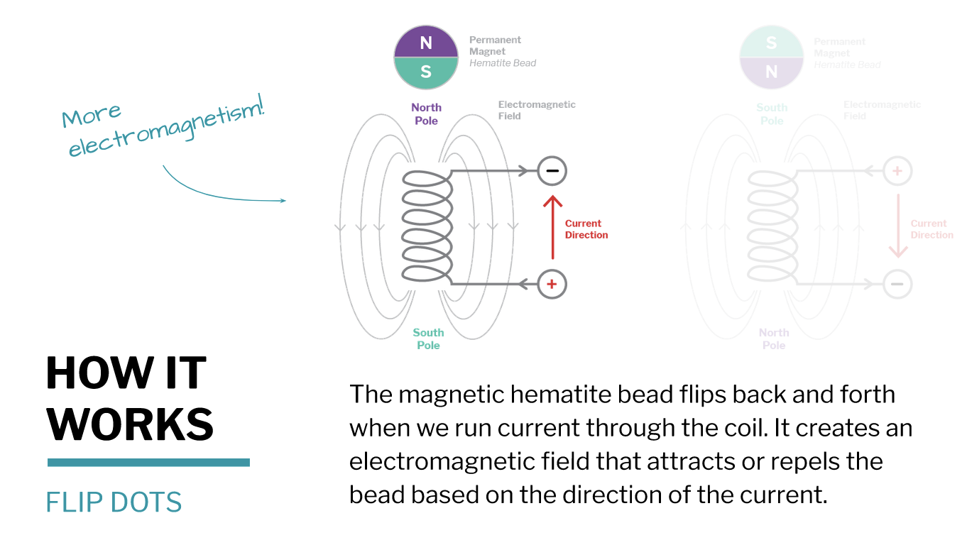
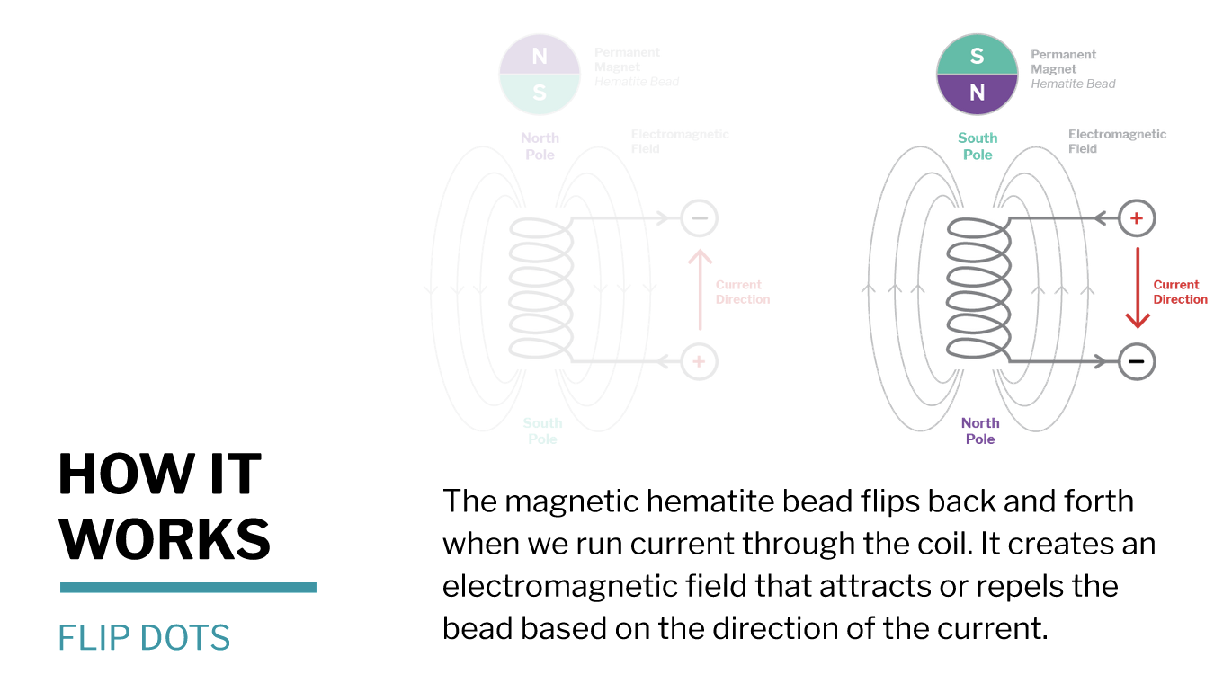 Slides are from Lisa Stark'course
So this is what we made :