5. E-textiles
This week I worked on E textiles analog and digital swatches and here is what I did.
Research and learning
Electronic textiles or e-textiles (often confounded with smart textiles) are fabrics that enable digital components such as a battery and a light (including small computers), and electronics to be embedded in them. "Smart textiles" are fabrics that have been developed with new technologies that provide added value to the wearer. Pailes-Friedman of the Pratt Institute states that "what makes smart fabrics revolutionary is that they have the ability to do many things that traditional fabrics cannot, including communicate, transform, conduct energy and even grow"
by Wikipedia
Circuits & Materials
I started with learning more about what a circuit is? What are soft and hard connections? and a bit of research about e-textiles and wearables
You can read more through this Link
I had available many conductive materials to use and experiment with.
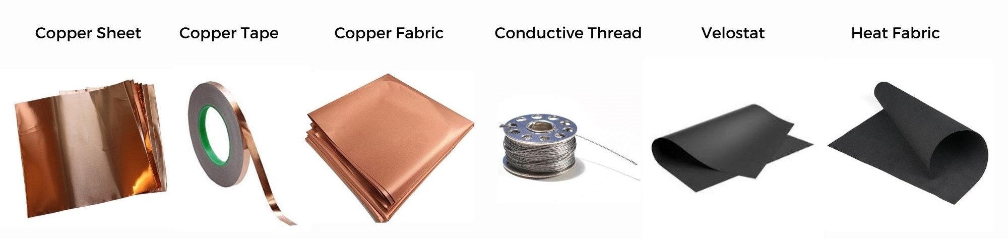
Conductive fabric offers electrical conductivity while maintaining softness and bendable properties. A great way to make soft switches with a low profile especially when hard switches are not applicable. it can be laser-cut, sewn, stretched, and manipulated in other ways that hard metals can not.
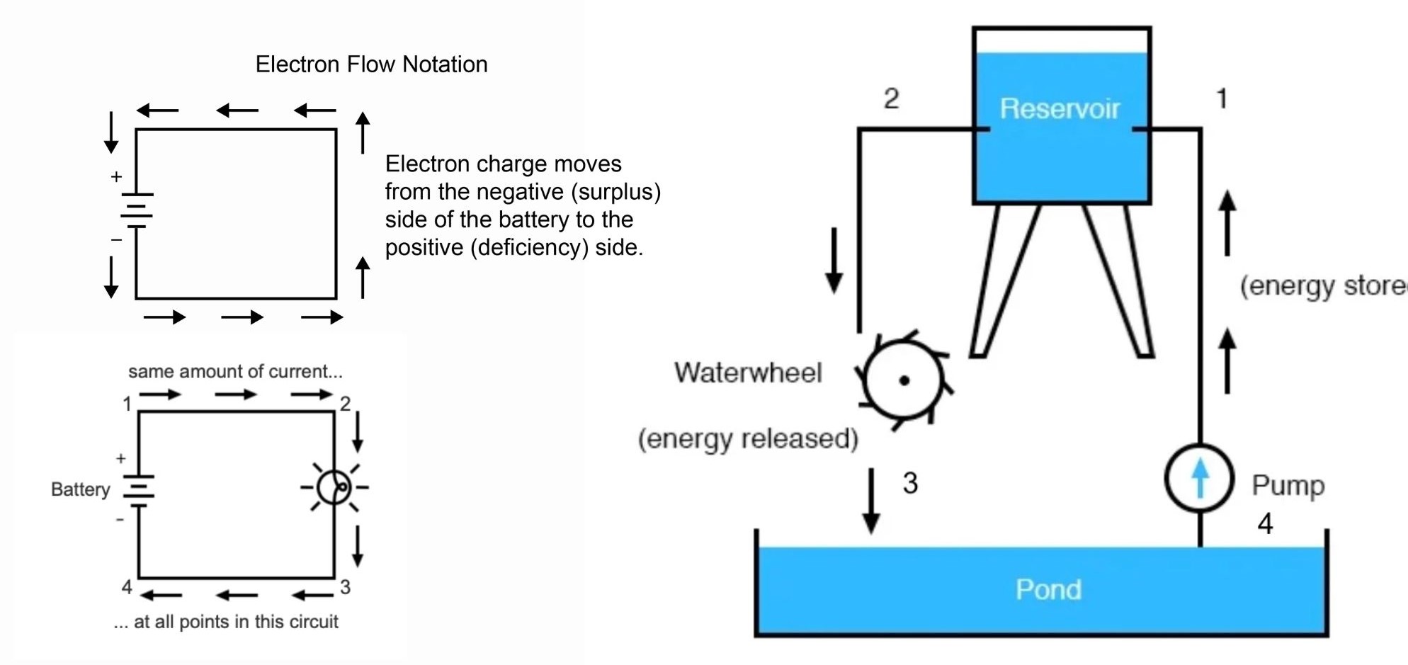
Ohms Law
It is a basic and an important law of electric circuits
Ohm’s law states that the voltage across a conductor is directly proportional to the current flowing through it, provided all physical conditions and temperature remain constant.
V = I x R

In words:
voltage = current x resistance
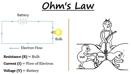
A basic electrical circuit consists of three main components, a source of voltage (battery), a load (lamp), and conductors( wires).
Usually all circuits will include a resistor.
A resistor works by restricting the flow of current among other uses. usually to to prevent a device from burning.
As the case of an simple circuit to light an LED. The LED resistance changes with the used voltage. when you increase the voltage, the resistance of the LED decreases, and according to Ohm’s law the current starts to increase. If we let the current increases to a certain limit, we may end up burrning the LED.
Using Multimeter
A Digital multimeter is a piece of test equipment that offers several electronic measurement tasks in one tool. The standard and basic measurements performed by multimeter are the measurements of amps, volts, ohms, and continuity.
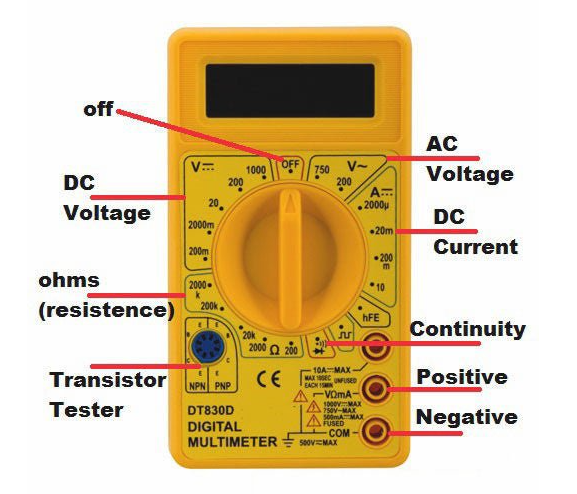
For more details check this Link on how to use a digital multimeter.
Arduino
Arduino is a programmable circuit board (microcontroller) that you can program to control and build electronics projects through an open-source software you download on your computer (Arduino), which is used to write and upload computer code to the physical board.
Arduino boards are able to read inputs (analog & digital) - light on a sensor, a finger on a button, etc - and turn it into an output - activating a motor, turning on an LED, etc.
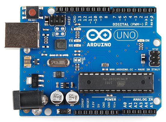
There are many types of Arduino boards but I mostly worked with Arduino UNO
The Circuit Playgroung Express
The Circuit Playgroung Express is a small microcontroller board with LEDs, buttons, and sensors built in. It can be powered from USB, "AAA" battery pack, or with a Lipoly battery. The possibilities using it are endless. You can light up multicolored LEDs, make sounds, play music, detect sound, light,motion and tempreture using built in sensors, and much more! Contains 14 pins in total. 8 can do analog inputs, multiple PWM output, for which one is a true analog output
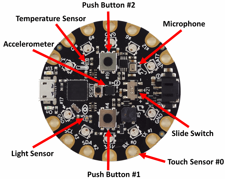
This Link explains what possibilities of inputs and ouputs using this circuit.
Digital switch
I used a hair clip for my first digital switch. Creating a hair clip that turns the light on when closed.
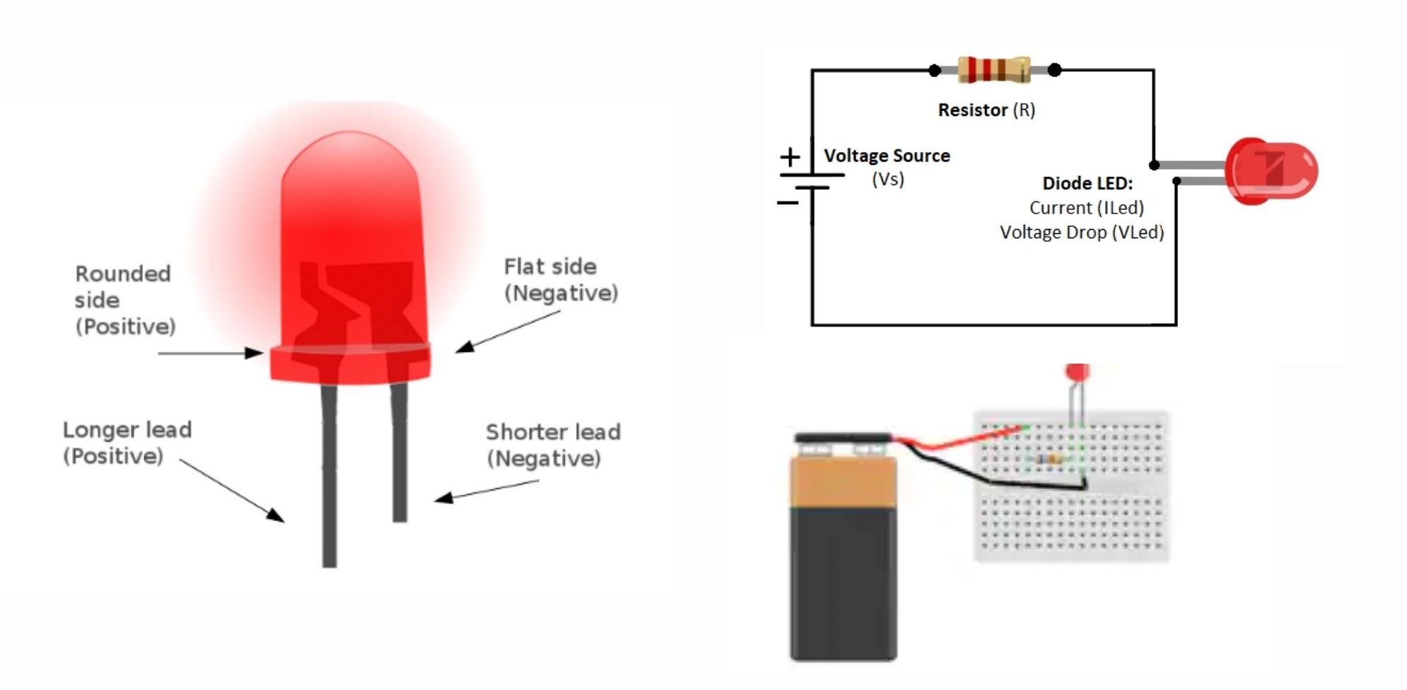
First, I used Arduino UNO as a power source which can be substituted by a 5v small battery ( also can be substituted using a 3 V battery without the use of a resistor ). Connected it to the breadboard for which I added my LED. A red LED in this case. I also added a resistor to make sure the LED doesn't burn.
The resistor needed depends on the following equation
Resistor = (Battery Voltage – LED voltage) / desired LED current

For only lighting an LED you need a resistor that matches the power source:

* Power source : 9V => R > 470 Ohm
* Power source : 5V => R > 220 Ohm
* Power source : 3V => no Resistor
LEDs have a long (positive side) and a short (negative side) so when you connect the circuit, it should flow from positive to negative.
After completing the circuit and plugging the Arduino in, I used the following code to make the light blink,
This is an illustration of the circuit

Arduino code
int LED = 2;
// the setup function runs once when you press reset or power the board
void setup() {
  // initialize digital pin LED_BUILTIN as an output.
  pinMode(LED, OUTPUT);
}

// the loop function runs over and over again forever
void loop() {
  digitalWrite(LED, HIGH);   // turn the LED on (HIGH is the voltage level)
  delay(500);                       // wait for a second
  digitalWrite(LED, LOW);    // turn the LED off by making the voltage LOW
  delay(500);                       // wait for a second
}
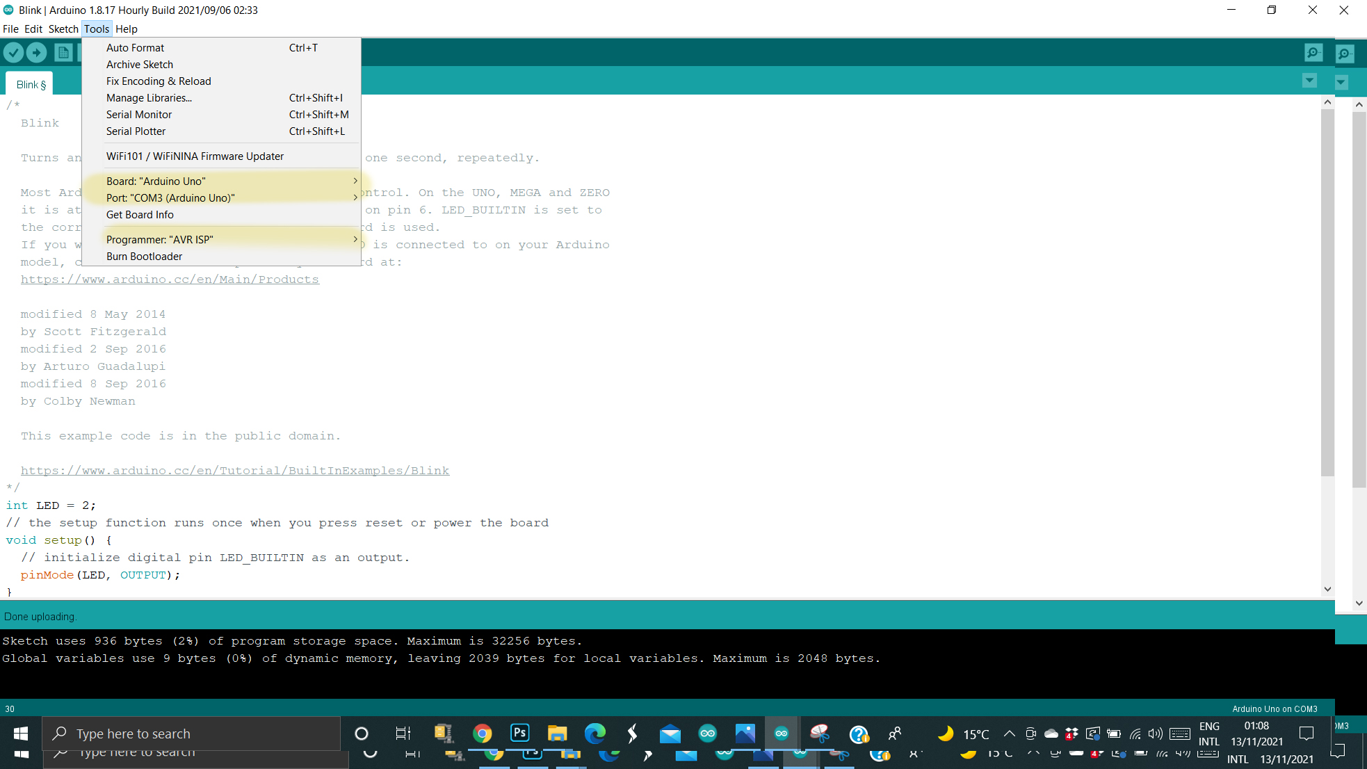
Note : Make sure Board, port, and programmer from Tools are assigned well.
Analogue switch / Potentiometer
It is a variable sensor that reads all values between the minimum and the maximum. Using a resistive conductive fabric like Velostat or heat fabric in this case. I connected a piece of the conductive fabric, each side to one end of the circuit.
To use the switch as a sensor, I used an extra 10k Ω resistor.
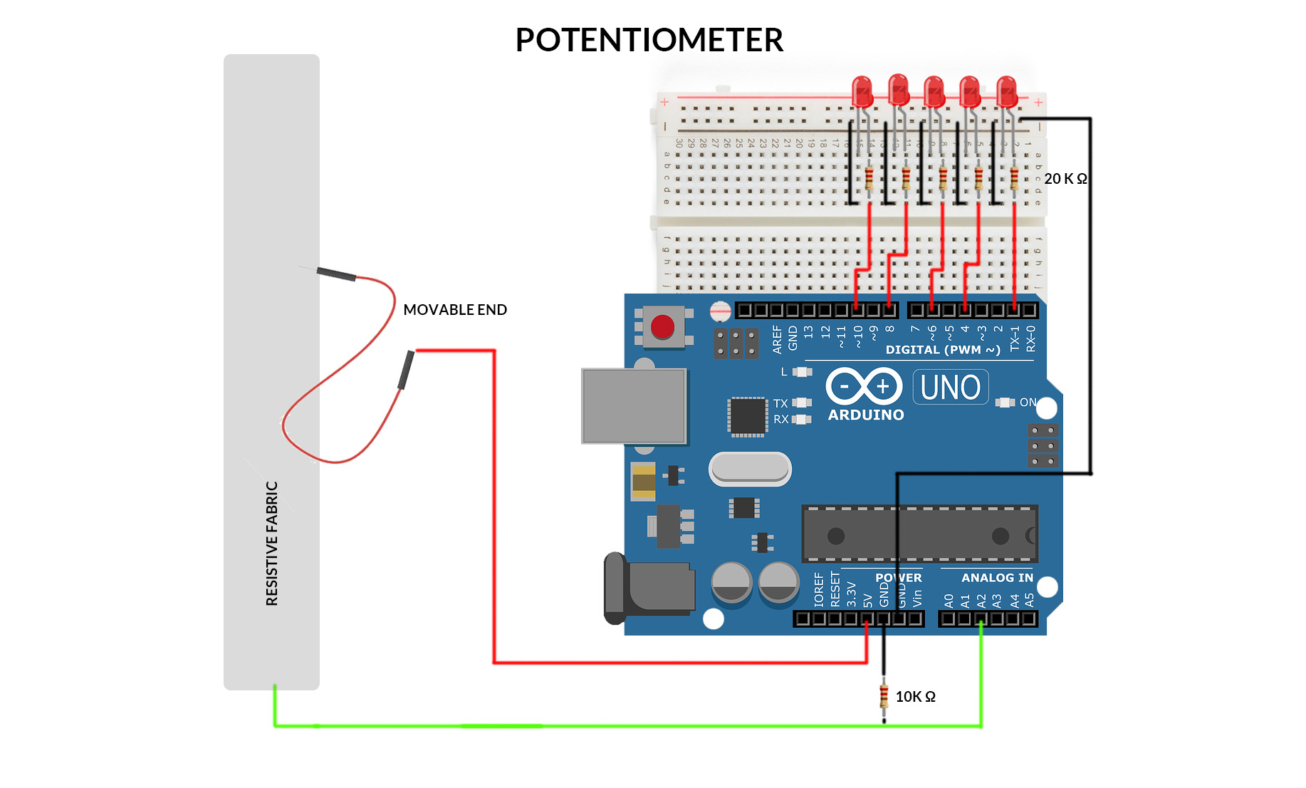
As you move the free cable across the resistive fabric the lights switch on or off ( depends on direction) sequentially.
Arduino code
Note : Make sure Board, port, and programmer from Tools are assigned well.
int resist = A2;
int light_1 = A1;
int light_2 = 4;
int light_3 = 6;
int light_4 = 8;
int light_5 = 10;

#include <Adafruit_NeoPixel.h>

void setup() {
  // put your setup code here, to run once:
  Serial.begin(9600);
  pinMode(light_1, OUTPUT);
  pinMode(light_2, OUTPUT);
  pinMode(light_3, OUTPUT);
  pinMode(light_4, OUTPUT);
  pinMode(light_5, OUTPUT);
}

void loop() {
  // put your main code here, to run repeatedly:

  int r = analogRead(resist);
  delay(500);
  Serial.println(r); //0-1000 R
  if ((r < 1020) && (r >= 10)) {

    if ((10 < r)&&(r <= 200)){
      digitalWrite(light_1, HIGH);
      digitalWrite(light_2, LOW);
      digitalWrite(light_3, LOW);
      digitalWrite(light_4, LOW);
      digitalWrite(light_5, LOW);
    }

    if ((200 < r) && (r <= 400)){
      digitalWrite(light_1, HIGH);
      digitalWrite(light_2, HIGH);
      digitalWrite(light_3, LOW);
      digitalWrite(light_4, LOW);
      digitalWrite(light_5, LOW);
    }

     if ((400 < r)&&(r <= 600)){
      digitalWrite(light_1, HIGH);
      digitalWrite(light_2, HIGH);
      digitalWrite(light_3, HIGH);
      digitalWrite(light_4, LOW);
      digitalWrite(light_5, LOW);
    }
        if ((600 < r) && (r <= 800)){
      digitalWrite(light_1, HIGH);
      digitalWrite(light_2, HIGH);
      digitalWrite(light_3, HIGH);
      digitalWrite(light_4, HIGH);
      digitalWrite(light_5, LOW);
    }
        if ((800 < r ) && (r <= 1020)){
      digitalWrite(light_1, HIGH);
      digitalWrite(light_2, HIGH);
      digitalWrite(light_3, HIGH);
      digitalWrite(light_4, HIGH);
      digitalWrite(light_5, HIGH);
    }
    }

   else{
   digitalWrite(light_1, LOW);
   digitalWrite(light_2, LOW);
   digitalWrite(light_3, LOW);
   digitalWrite(light_4, LOW);
   digitalWrite(light_5, LOW);
  }

}
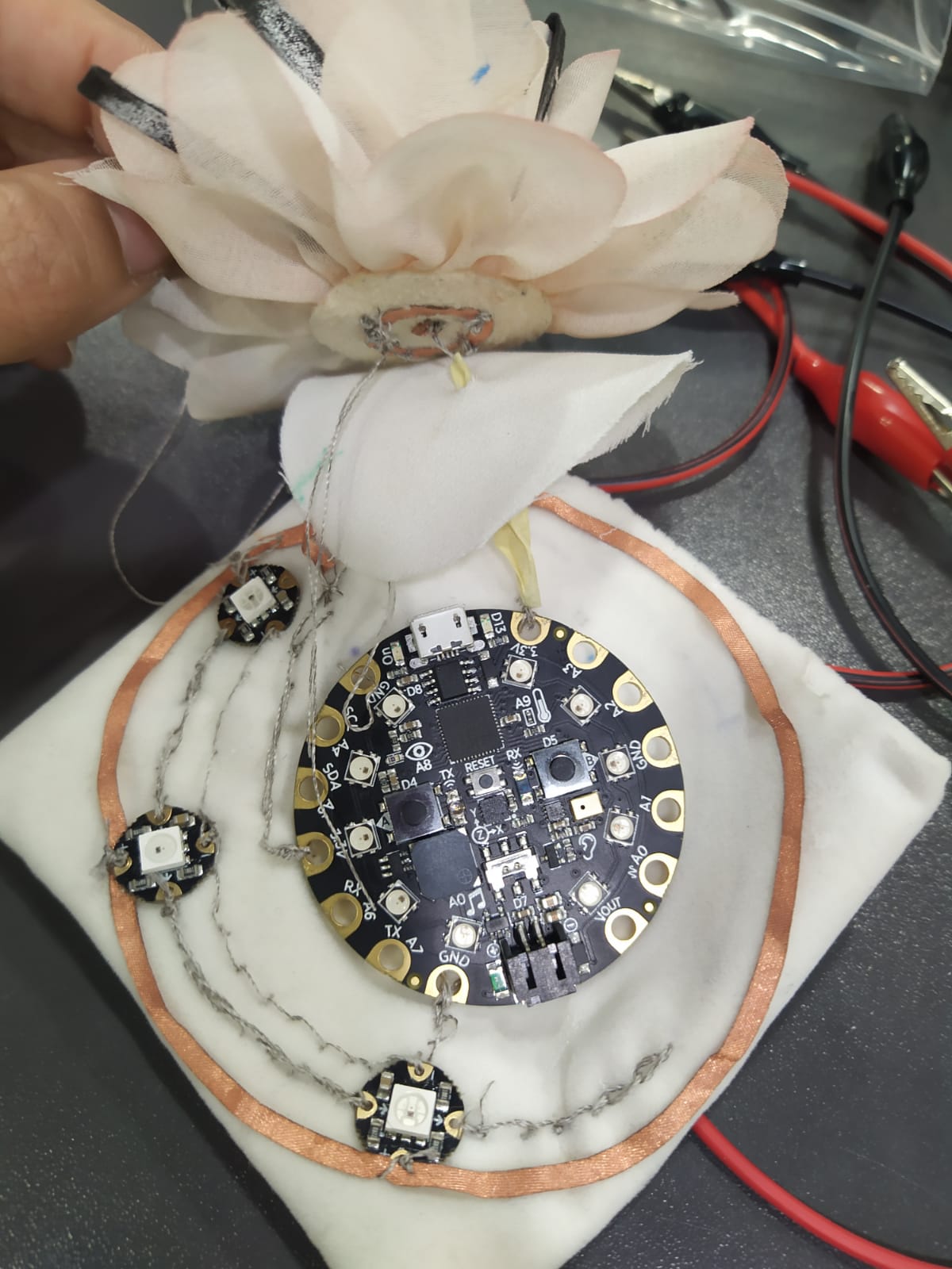
Project

A project inspired by Corsages and windchimes. Instead of the wind creating a musical, Stroking the petals create a musical of colors. Ment to express the movement and sense of touch.
I used the following materials:
* adafruit circuit playground express
* Conductive thread
* 3.7 v LiPo battery
* copper fabric
* sewable neopixels
* Heat fabric (resistor fabric)
* fabric flower and base
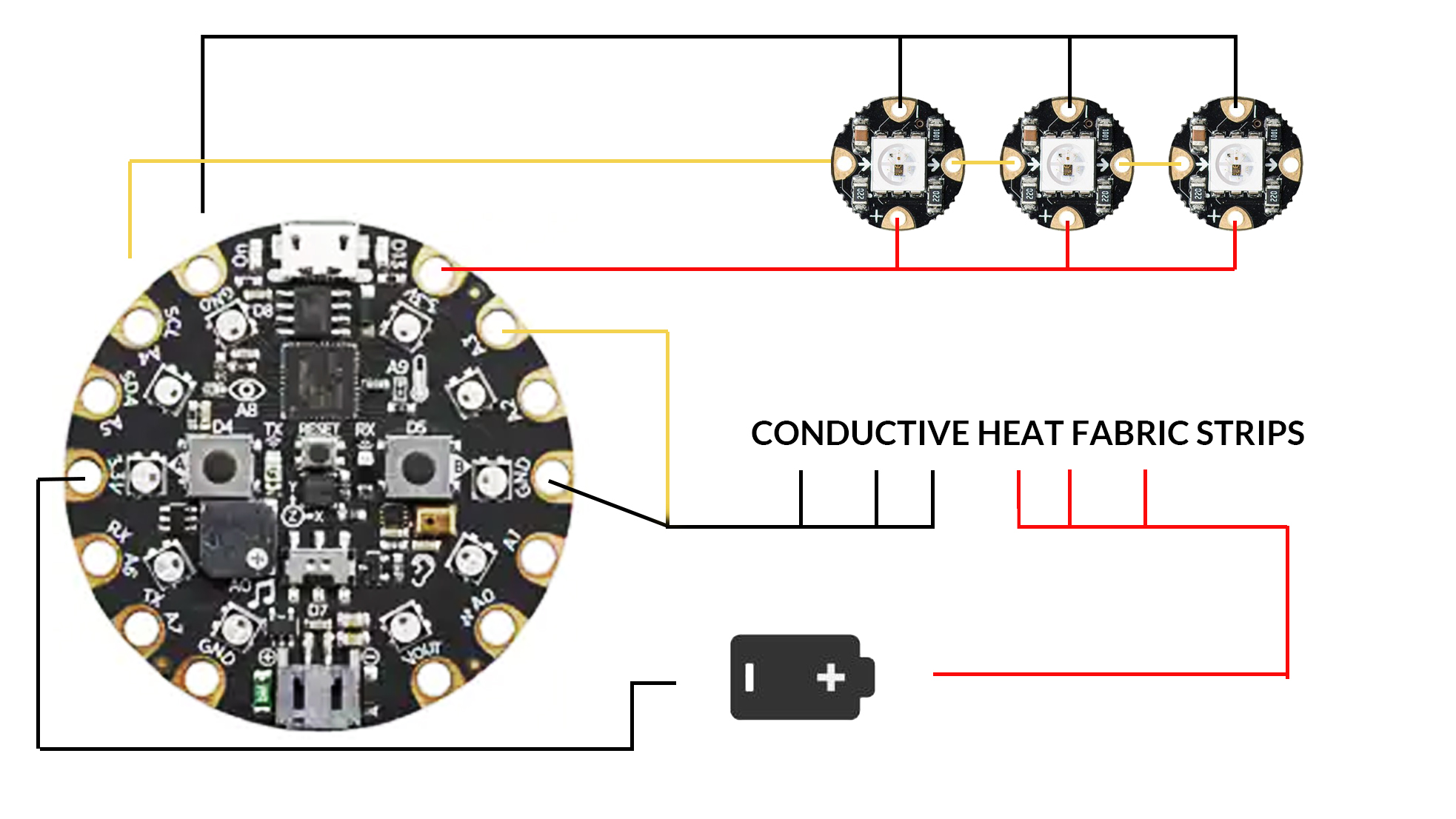
Here is an illustration of how the sensor works.
- Started by laser cutting circles using rhino and trotec
Laser cut setting for the copper fabric:
Power: 20
Speed: 1.8
-
Hand cutting small pieces of Heat fabric ( connective fabric) and gluing it on the desired recycled head piece flower so whn you move your hand through the flower they might connect or touch.
-
Using the connective thread I attached half of the touching pieces to the adafruit ground while the other half to the adafruit power supply.
-
Made sure to create a fabric layer between the flower piece and the adafruit circle to make sure no undesiered connections happening. created a void in the foam base for the battery and made sure it can be changed regularly.
Note : Make sure to use "adafruit circuit playground express" for the board
Arduino code
#include <Adafruit_NeoPixel.h>
#ifdef __AVR__
  #include <avr/power.h>
#endif

// Which pin on the microcontroller board is connected to the NeoPixels?
#define PIN            A4  // For Circuit Playground Express

// How many NeoPixels are attached to the board?
#define NUMPIXELS      3

// When we setup the NeoPixel library, we tell it how many pixels, and which pin to use to send signals.

Adafruit_NeoPixel pixels = Adafruit_NeoPixel(NUMPIXELS, PIN, NEO_GRB + NEO_KHZ800);

int delayval = 100; // delay for half a second

int RED = pixels.Color(255, 0, 0);    // ints work better for me
int GREEN = pixels.Color(0, 255, 0);
int BLUE = pixels.Color(0, 0, 255);

void setup() {
  Serial.begin(9600);
  pixels.begin(); // This initializes the NeoPixel library.
}

void loop() {
   int i;              // loop variable
   int value;          // analog read of potentiometer
   int display_value;  // number of NeoPixels to display out of NUMPIXELS

   // Read PIN value and scale from 0 to NUMPIXELS -1
   value = analogRead(A3);
   //Serial.print(value);
   Serial.println(value);
   display_value = int(value  * NUMPIXELS / 1023);
   //Serial.println(display_value);

   // For a set of NeoPixels the first NeoPixel is 0, second is 1, all the way up to the count of pixels minus one
  if ((value>=0)&& (value<3)){
    for(i=0; i<value; i++){  // pixels.Color takes RGB values, from 0,0,0 up to 255,255,255
      pixels.setPixelColor(i, 0, 0, 0);

    }
    }
  if ((value>=3)&& (value<10)){
    for(i=0; i<value; i++){  // pixels.Color takes RGB values, from 0,0,0 up to 255,255,255
      pixels.setPixelColor(i, 230, 209, 52);
    }
  }

    if ((value>=10)&& (value<20)){
    for(i=0; i<value; i++){  // pixels.Color takes RGB values, from 0,0,0 up to 255,255,255
      pixels.setPixelColor(i,230, 60, 100);
  }
  }
    if ((value>=20)&& (value<50)){
    for(i=0; i<value; i++){  // pixels.Color takes RGB values, from 0,0,0 up to 255,255,255
      pixels.setPixelColor(i, 100, 0, 100);
    }
  }
    if ((value>=50) && (value<160)){
    for(i=0; i<value; i++){  // pixels.Color takes RGB values, from 0,0,0 up to 255,255,255
      pixels.setPixelColor(i, 230, 52, 73);
    }
  }
    if ((value>=160)&& (value<250)){
    for(i=0; i<value; i++){  // pixels.Color takes RGB values, from 0,0,0 up to 255,255,255
      pixels.setPixelColor(i, 227, 115, 131);
    }

  }
    if ((value>=0)&& (value<6)){
    for(i=0; i<value; i++){  // pixels.Color takes RGB values, from 0,0,0 up to 255,255,255
      pixels.setPixelColor(i, 0, 0, 0);
    }
    }
   pixels.show(); // This sends the updated pixel color to the hardware.

   delay(delayval); // Delay for a period of time (in milliseconds).
The result was not as satisfactory. Although it works at times, Sometimes the lights will not work as planned. Although the analog input is readable through the serial print, the connections were a bit off. Probably due to the sewing and connecting from my part as all it tricky working and sewing within tight areas. If I used the lights that are part of the adafruit microcontroller, It would have probably worked perfectly.
For connecting multiple sewable neopixels to adafruit you can check this useful Link