8. W E A R A B L E S
I N S P I R A T I O N
All Direction Is Curved, All Motion Is Spiral at Easttopics Gallery from EJTECH on Vimeo.
Sound_Embroidery from claire wiliams on Vimeo.
Installation textile avec 2 Microphones textiles et 4 hautparleurs textiles. from Ryth Kesselring on Vimeo.
LilyKorg test#1 from Afrdt on Vimeo.
A C T U A T O R S
Actuators are those that perform actions commanded by the controller and are capable of transforming an electrical signal into sound, magnetism, movement, heat, among others.
S O U N D
Sound is a type of energy made when something vibrates.
Soft Speaker
How a Speaker Works

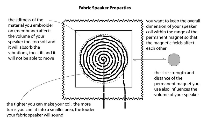
A speaker is a coil of a highly conductive material wound in close proximity to a magnet producing an electromagnetic field when electric current flows. This electromagnetic field translates the electrical signal into an audible sound. Therefore, the stronger the magnet and the more conductive the coil material, the louder the speaker volume.

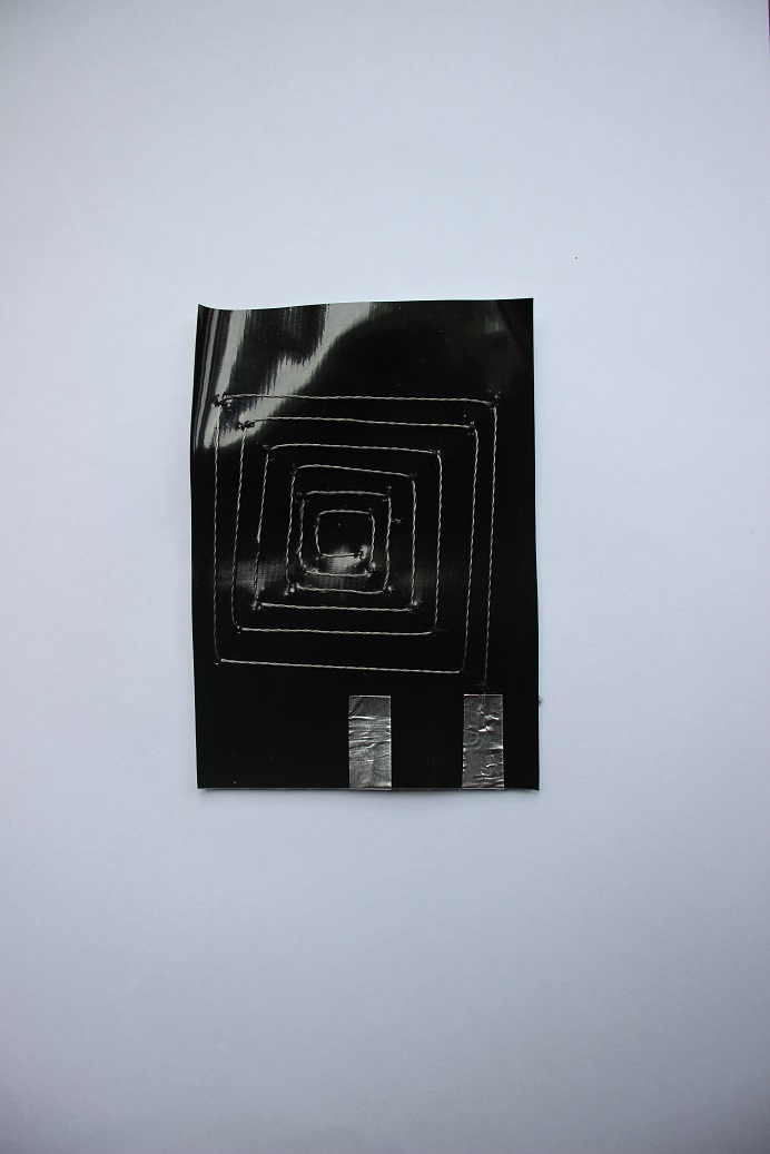
Constructing a Soft Speaker
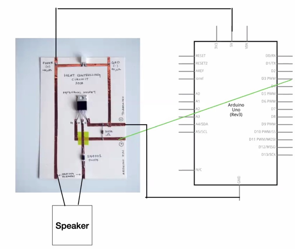
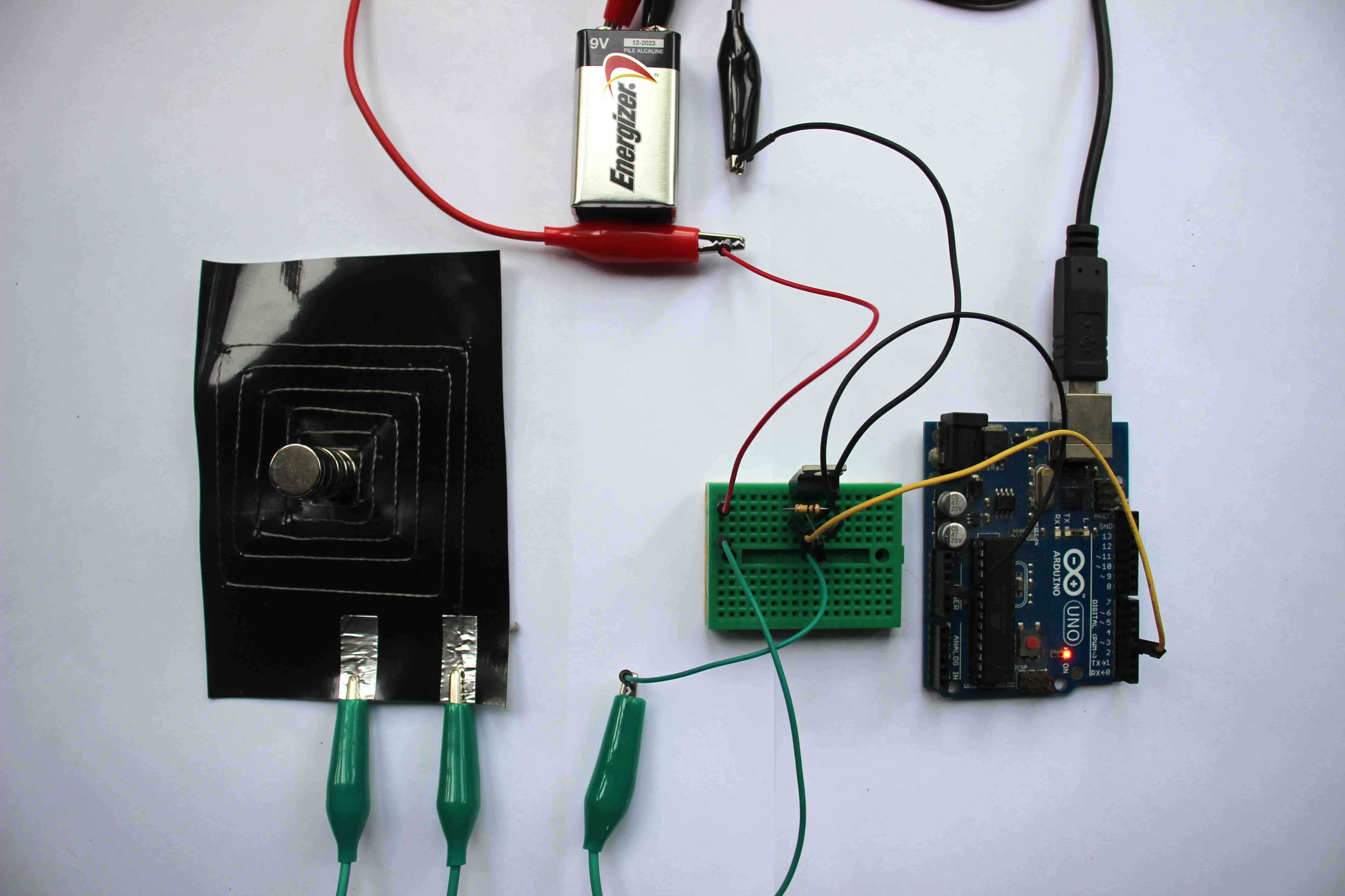
Testing with Arduino
To control the soft speaker through arduino it was necessary to use a circuit driver as shown in the diagram below:
and I used this code:
const int speaker = 3; //buzzer to arduino pin 3


void setup(){

  pinMode(speaker, OUTPUT); // Set buzzer - pin 3 as an output

}

void loop(){

  tone(speaker, 1000); // Send 1KHz sound signal...(from 20 to 20000Hz)
  //tone(pin, frequency);
  delay(1000);        // ...for 1 sec
  noTone(speaker);     // Stop sound...
  delay(1000);        // ...for 1sec

}
References
Soft Speakers: Digital Embroidering of DIY Customizable Fabric Actuators
https://www.kobakant.at/DIY/?p=5935
In this activity I will get to know and test possible input and output electronic components that I can use in my final project
Detecting the intensity of ultraviolet
UV radiation is a form of electromagnetic radiation with wavelength from 200 nm to 370 nm, shorter than that of visible light, but longer than X-rays.
I used the UVM30A sensor to detect the intensity of ultraviolet radiation. I found in the datasheet a graph that represents the sensor output in mV in relation to the UV index. The output signal consists of a voltage of 0 to 1 V and the current varies between 0.06 and 0.1 mA.
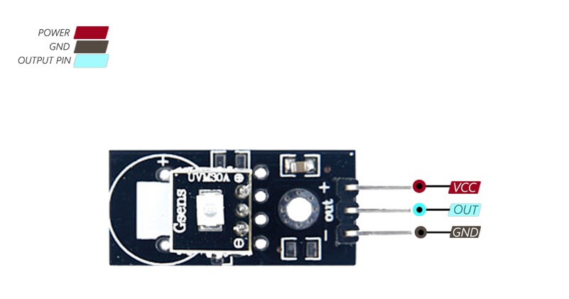
# UV Sensor Uvm 30a
This module has 3 pins:
VCC: Module power supply – 3V to 5V GND: Ground OUT (SIG): Output analog signal – varies from 0-1 V
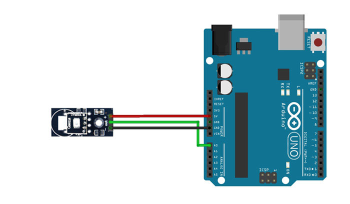
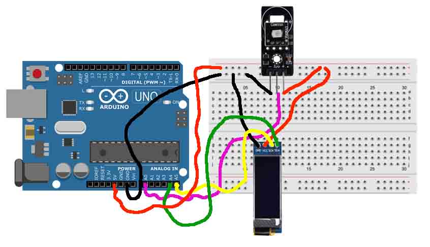
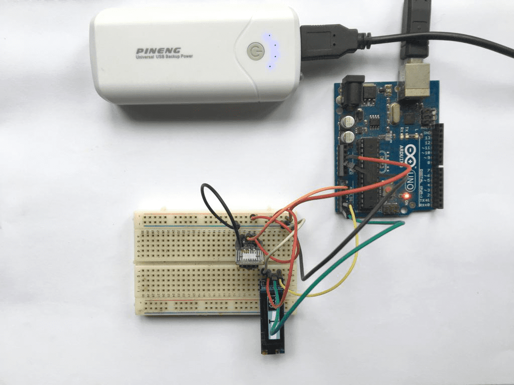
Connection between UV sensor and Arduino
Circuit
Code
I used the sample code in the datasheet:
int sensorValue = A0

void setup(){
  Serial.begin(9600);
}

void loop()
{
  int sensorValue;

 sensorValue=analogRead(A0);
 Serial.print("The voltage value:");
 Serial.print(sensorValue*5000/1023.0);
 Serial.println("mV");
 delay(1000);
 Serial.print("\n");
}
After I sent the code to the Arduino board through its software, I opened the serial monitor and as I approached my smartphone's flashlight I noticed the variation of the output in mV.
OLED display 128x32
Visualization interface
The OLED display size of 0.91″, resolution of 128 x 32 pixels and I2C communication interface is used to show information in graphic and text format.
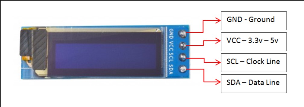
OLED Display Module Pinout
This module has 4 pins: >>VCC: Module power supply – 3V to 5V >>GND: Ground >>SDA: Data >>SLC: Clock
Circuit
| DISPLAY | ARDUINO |
|---|---|
| GND | GND |
| VCC | 5V |
| SDA | A4 |
| SLC | A5 |
Testing the Display with Arduino
In order to issue commands and control the screen I had to install two libraries in the Arduino IDE: The SSD1306 driver library used to initialize the display and the GFX library used for functions to display text, draw lines and circles, etc.
To install the library navigate to the Sketch > Include Library > Manage Libraries… Wait for Library Manager to download libraries index and update list of installed libraries.
After installing the two libraries I went to the arduino IDE menu under
File → Examples → Adafruit SSD1306 → ssd1306_128x32_12c. After opening the example sketch ssd1306_128x32_12c , I uploaded it to the Arduino board with the OLED wired, as shown in the table above. The OLED display started showing a demo that displays various text and graphics on the screen.
Viewing UV sensor data with the oled display
Circuit
Code
#include <SPI.h>
#include <Wire.h>
#include <Adafruit_GFX.h>
#include <Adafruit_SSD1306.h>

//Resolucao do display Oled (em pixels)
#define SCREEN_WIDTH 128
#define SCREEN_HEIGHT 32

#define OLED_RESET 4 // Reset pin # (or -1 if sharing Arduino reset pin)
Adafruit_SSD1306 display(SCREEN_WIDTH, SCREEN_HEIGHT, &Wire, OLED_RESET);

int indiceUV;

void setup()
{
  Serial.begin(9600);

  //Checagem do display no endereço I2C 0x3C
  if (!display.begin(SSD1306_SWITCHCAPVCC, 0x3C))
  {
    Serial.println(F("SSD1306 allocation failed"));
    for (;;); //Para o programa
  }

  //Inicializa o display Oled
  display.display();
  delay(2000);
}

void loop()
{
  //Leitura dos dados do sensor
  int leitura_porta = analogRead(A0);

  //De acordo com a leitura define o indice UV corrrspondente
  if (leitura_porta <= 10) {
    indiceUV = 0;
  } else if (leitura_porta > 10 && leitura_porta <= 46) {
    indiceUV = 1;
  } else if (leitura_porta > 46 && leitura_porta <= 65) {
    indiceUV = 2;
  } else if (leitura_porta > 65 && leitura_porta <= 83) {
    indiceUV = 3;
  } else if (leitura_porta > 83 && leitura_porta <= 103) {
    indiceUV = 4;
  } else if (leitura_porta > 103 && leitura_porta <= 124) {
    indiceUV = 5;
  } else if (leitura_porta > 124 && leitura_porta <= 142) {
    indiceUV = 6;
  } else if (leitura_porta > 142 && leitura_porta <= 162) {
    indiceUV = 7;
  } else if (leitura_porta > 162 && leitura_porta <= 180) {
    indiceUV = 8;
  } else if (leitura_porta > 180 && leitura_porta <= 200) {
    indiceUV = 9;
  } else if (leitura_porta > 200 && leitura_porta <= 221) {
    indiceUV = 10;
  } else {
    indiceUV = 11;
  }

  //Mostra os valores no Serial Monitor
  Serial.print("Valor porta: ");
  Serial.print(leitura_porta);
  Serial.print(" - Indice: ");
  Serial.println(indiceUV);

  //Apaga o display
  display.clearDisplay();

  //Desenha retangulos
  display.fillRect(46, 0, 81, 32, SSD1306_INVERSE);
  display.drawRect(0, 0, 45, 32, SSD1306_WHITE);
  display.display();

  //Define tamanho da fonte
  display.setTextSize(1);
  //Texto com letras em branco
  display.setTextColor(SSD1306_WHITE);
  //Posicao do cursor
  display.setCursor(4, 3);
  display.println(F("INDICE"));
  display.setCursor(12, 14);
  display.setTextSize(2);
  display.println(F("UV"));

  display.setTextSize(4);
  //Texto invertido, com texto preto e fundo branco
  display.setTextColor(SSD1306_BLACK, SSD1306_WHITE);
  display.setCursor(65, 2);
  display.println(indiceUV);

  display.display();
  delay(2000);
}
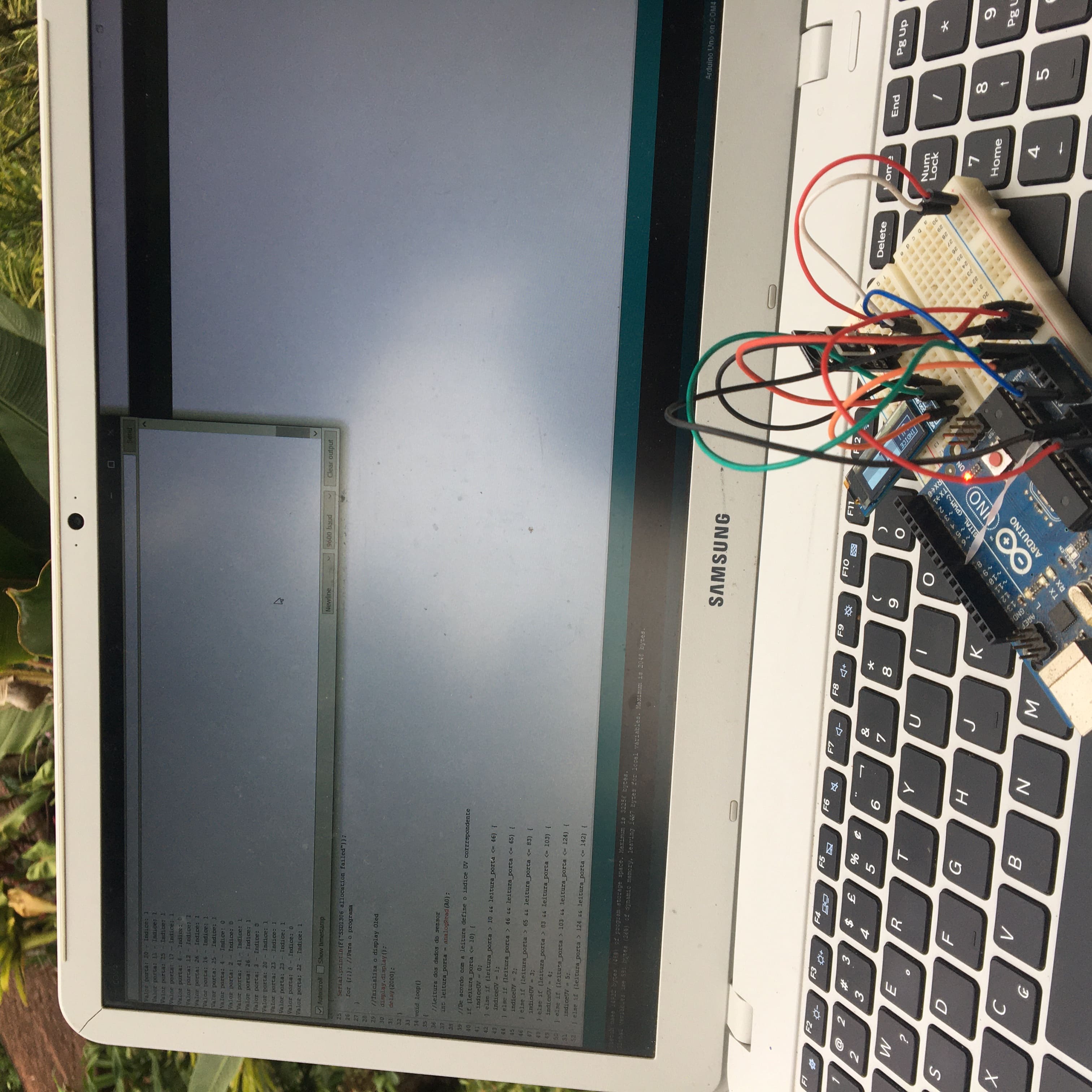
When loading the code to the arduino this will make it read the analog pin 0 (A0) to which the sensor output is connected and convert it to mV so that we can compare with the values of the UV index table and calculate the UV index at that specific location and time. After the calculation and determination of the UV index, the index is displayed on the 128x32 oled Display.
Research
Guide for oled display with arduino