8. Wearables
Learning outcomes
- References and Concept development
- Design: program a microcontroller, design circuit and schematic
- Fabrication: Integrate inputs and outputs in a microcontroller wearable project
- Documentation: Anyone can go through the process, understand it and reproduce it
- Final outcome: Assembled project, functioning and complete
- Originality - Aesthetics: Has the design been thought through and elaborated?
Student checklist
- Document the concept, sketches, references also to artistic and scientific publications
- Create a swatch/sample using an ATTiny/Arduino/Adafruit with one input and one output, using hard-soft connection solutions and battery
- Create 2 actuator swatches and test them with the Arduino or ATTiny, chosing from examples such as: motors / mini vibration, leds / neopixels, flip dot / electromagnet, heat pad / with thermochromic coating, speaker / mp3 player, SMA (shape memory alloy)
- Learn how to program an Arduino/ATTiny/Adrafruit, documenting your process, the libraries added, power requirements and source code
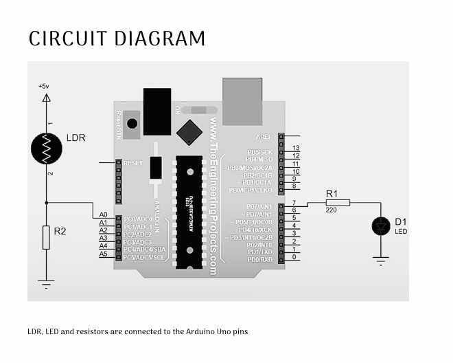
- Document the schematic and circuit
- Upload a small video of your object working
- Integrate it to a project (extra credit) Initially my idea was to detect the temperature of the dog/cat using temperature sensor LM35 and show it on the collar. Then I decided to use an LDR sensor that detects the presence or absence of light. I decided to use an LDR sensor and make a dog collar. The dog collar will have LEDs across it and and an LDR sensor. When there is low light, the LEDs should light up and when the light is high, LEDs won't light up.
Cat collar with LDR Sensor
I want to build a cat collar that has a lilypad and battery sewn into it. But with supplies being limited I decided to make use of the collar from etextiles week to make the collar with sensor.
What is an LDR Sensor?
** Spiralling my way into the week**
** 1.Make an LED light up when connected to battery**
** 2.Make an LED light up when it is dark with an LDR sensor** How to make a Dark Sensor This video shows how to set up Arduino and connect an LED to light up:
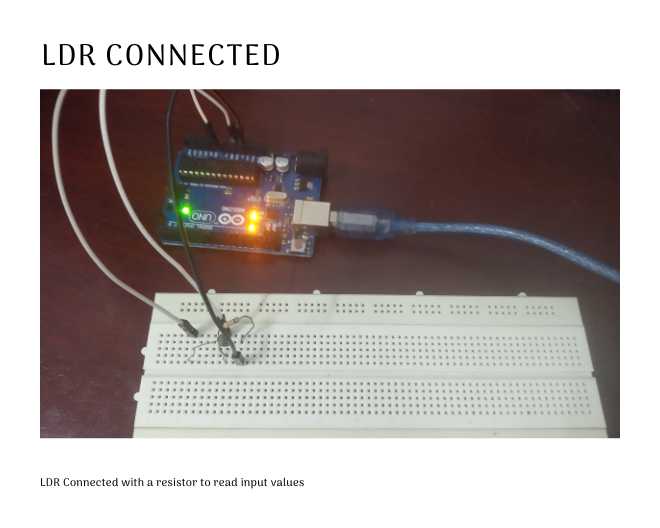
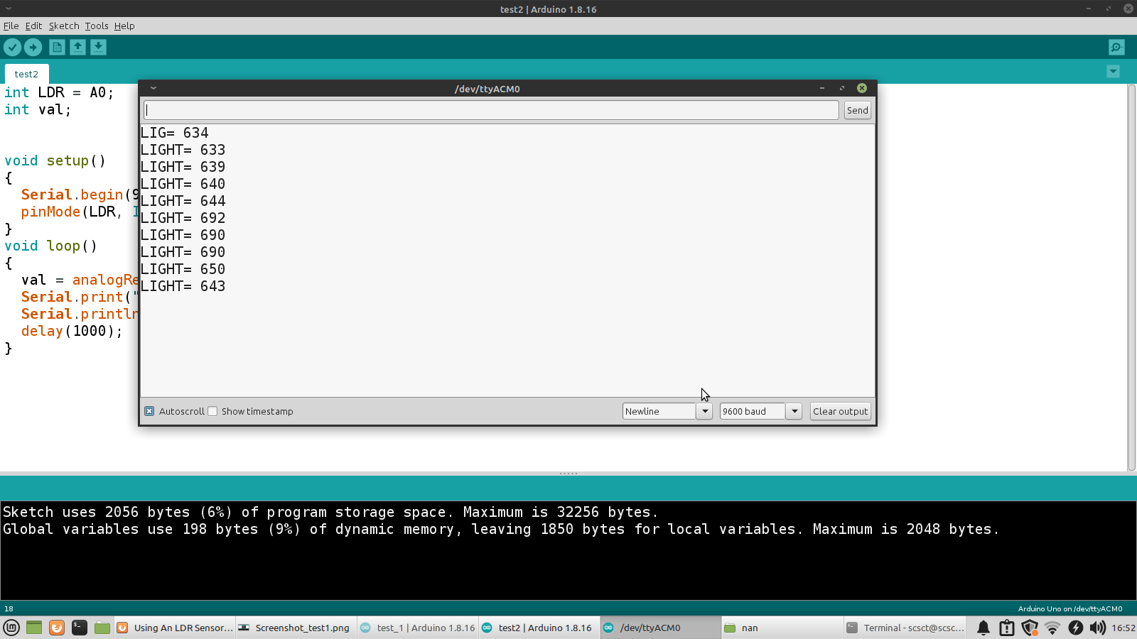
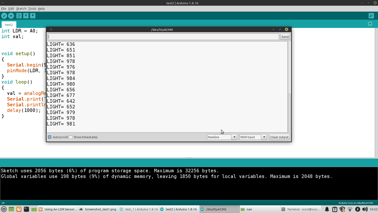
Finding how the resistance changes in an LDR sensor
Next I connected an LDR with a resistor to read the input light values
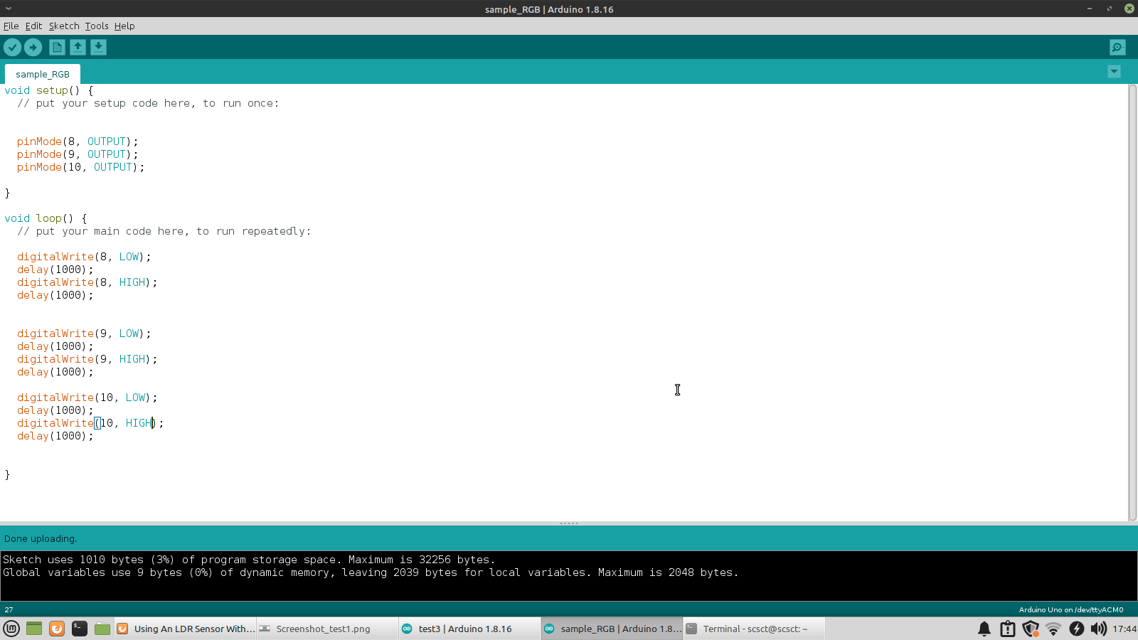
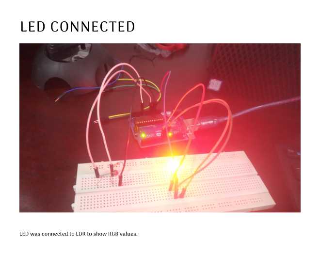
I test programmed an LED to show RGB values.
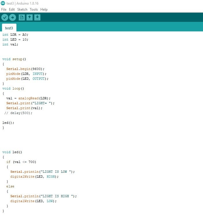
I wrote a program to light up the builtin LED of the Arduino when there is low light.
int ldrPin=A0;
int ldrVal=0;
int ledPin=LED_BUILTIN;
void setup() {
  // put your setup code here, to run once:
Serial.begin(9600);
pinMode(ledPin,OUTPUT);
}

void loop() {
    // put your main code here, to run repeatedly:
ldrVal= analogRead(ldrPin); //0-1023
Serial.println(ldrVal);
if(ldrValint ldrVal=0;)
{
  digitalWrite(ledPin,HIGH);
  Serial.println("on");
}
else
{
  digitalWrite(ledPin,LOW);
  Serial.println("off");
}
delay(100);
}
Next I connected an external LED and a 220 ohm resistor to Pin 7.
For switching on the external LED when there is low light, I used the same code but changed the LED_BUILTIN(in line 3) with the pin to which the LED is connected, ie Pin 7.
int ledPin=7;
After this I used the same cat collar I made in week 5 and connected it with the circuit.
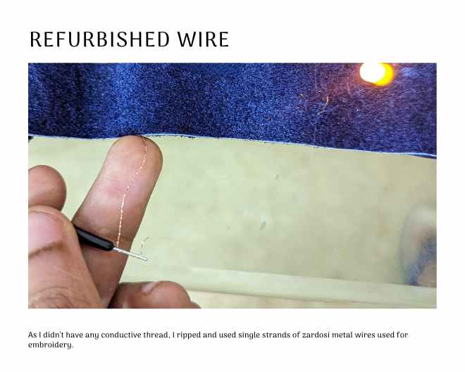
As I didn't have much supplies I had to refurbish everything. I ripped some embroidery threads that I was planning to make Speaker with. I used a strand of the thread for connctions.
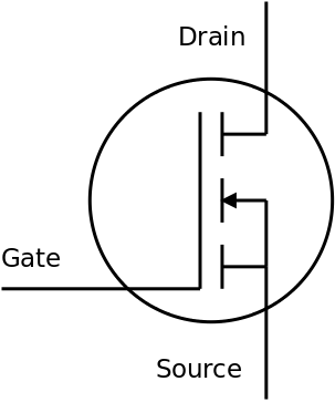
Preparing Actuators:MOSFET circuits
To create a circuit using an N-Channel MOSFET transistor, follow these steps:
Materials needed:
Copper tape Regular tape N-Channel MOSFET transistor Soldering iron and solder Pliers 9V battery clip 1N4007 diode (optional, for safety) Steps:
Apply the copper tape in the pattern shown below, ensuring that the traces are aligned correctly. Use regular tape to insulate the middle and left MOSFET traces from each other. This will prevent them from making contact.
Carefully use the pliers to bend the legs of the MOSFET. Make sure they are far enough apart from each other so that the copper traces won't touch. Also, ensure that the MOSFET lies flat on the paper.
Solder the legs of the MOSFET and the 9V battery clip to the respective copper tape traces. Double-check the connections to ensure they are secure.
If you want to add an extra layer of safety, you can include a 1N4007 diode. Connect the diode in parallel with the load (e.g., motor or heating pad) for better protection.
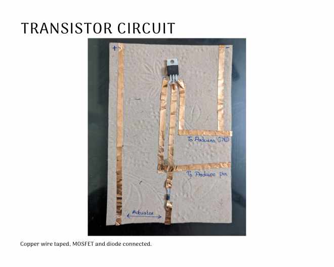
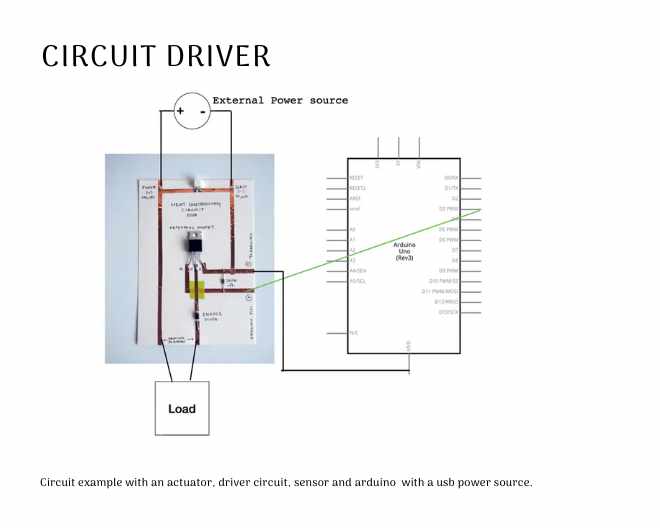
By following these steps, you will have successfully set up an N-Channel MOSFET circuit that can control the power flow to a high-power actuator using an IC or microcontroller. This arrangement allows you to power the IC at a lower voltage while using its control signals to manage the flow of higher power from a separate secondary power source to the actuator. It's a useful way to control devices that require different operating voltages within a single control circuit.
I wound some zardosi embroidery thread like a coil and placed a 10mm magnet from an old bag project of mine in the middle. This should create an electromagnet.
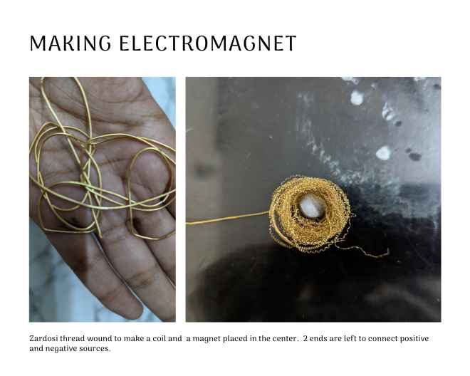
Here I tested it's working.
Bill of Materials
| Qty | Description | Price | Link |
|---|---|---|---|
| 1 | Arduino Uno | Lab inventory | |
| 1 | Resistor 220 ohm | Lab inventory | |
| 1 | Resistor 1 kohm | Lab inventory | |
| 1 set | Jumper wires | Lab inventory | |
| 1 | LDR resistor | Lab inventory | |
| 1 | 9v Battery | Lab inventory | |
| 1 | IRF230 mosfet | Lab inventory | |
| 1 | IN4001 Diode | Lab inventory | |
| 2 | neodymium magnet 10mm | Lab inventory | |
| 1 | Coil | Lab inventory | |
| 1 | Thick paper/card | Lab inventory | |
| 1 | Copper Tape | Lab inventory |
Files
Files can be downloaded from here