13. Skin Electronics
Learning outcomes
- References and Concept development
- Design: Program a microcontroller, design circuit and schematic
- Fabrication: Capable of Integrating inputs and outputs in a microcontroller project
- Documentation: Anyone can go through the process, understand it and reproduce it
- Final outcome: Is the project assembled, functioning and complete
- Originality - Aesthetics: Has the design been thought through and elaborated?
Student checklist
- Document the concept, sketches, references also to artistic and scientific publications
- Design a “skin-circuit”, exploring the replication of the examples below or: the Skin masquerade party project, the Twinkle Nails project, interactive tattoo, explore how to create a new skin electronics accessory.
- Document the project and included all source files and all materials used
- Upload your design files and source code
- Make a video with your skin electronic working
- Make a short performance/concept of your project functioning (extra credit)
Research
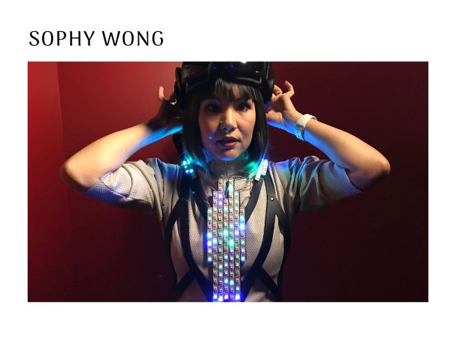
Physics Kitty Helen Leigh Sophy Wong

Concept Development
I want to use my fingers as a sensor. Using fingers as sensors is a fascinating concept that involves capturing and interpreting finger movements to perform certain actions. In this specific case, the goal is to create a system where moving the fingers in a particular direction will turn on a light, while moving them in another direction will turn it off.
To achieve this, several components and technologies may be required, such as sensors, microcontrollers, and programming languages. One possible approach is to use a flex sensor, which can detect the direction and degree of finger movement, and convert it into an electrical signal that can be processed by a microcontroller.
The microcontroller can then be programmed to interpret the signal and activate or deactivate a light accordingly. The programming language used may depend on the microcontroller chosen, but popular options include Arduino and Raspberry Pi.
To make the system more user-friendly, it may be beneficial to include a feedback mechanism that lets the user know when the light has been turned on or off, such as an LED indicator. Additionally, the system could be designed to be wireless, allowing the user to control the light from a distance using a smartphone app or remote control.
Overall, using fingers as sensors can open up many possibilities for intuitive and interactive control systems, and this specific application of controlling a light can have practical uses in various settings, such as in homes, offices, and public spaces.
Design
I started doing from the very beginning of all the electronics assignments, Downloaded Arduino IDE on to my laptop, added the drivers,


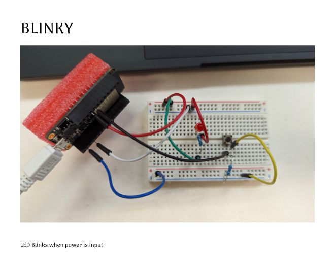
I made a blinky circuit and decided to make improvements on it to make the Skin sensor
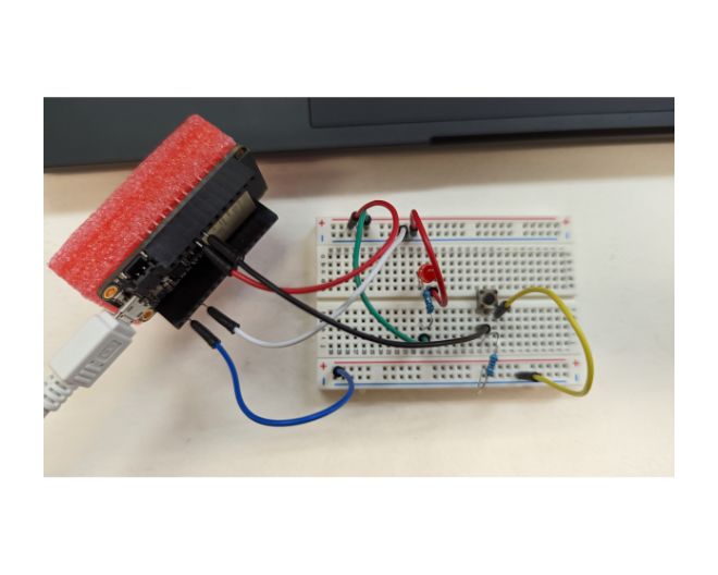


Voltage Divider Circuit
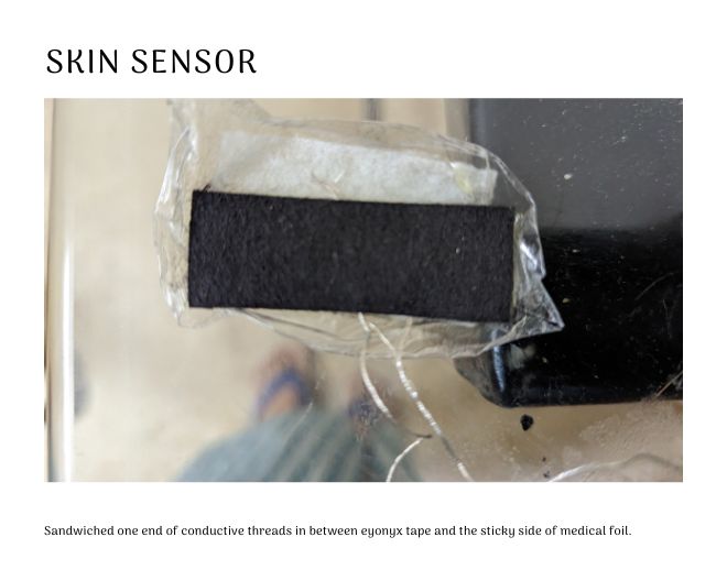
Skin Sensor
I made a quick sensor using Eonex Conductive fabric and Conductive Thread.
I wanted to work on developing stretch sensors using fabrics that possess conductive and resistive properties that change based on the stretching of the fabric. My aim is to create an easy-to-use stretch sensor that could open up new possibilities in the field. I tried using stretchy fabrics from Eeonyx, which are coated with doped polypyrrole, a conducting polymer. While the initial results are promising, we still need to test the sensors in a specific situation to evaluate their performance accurately.
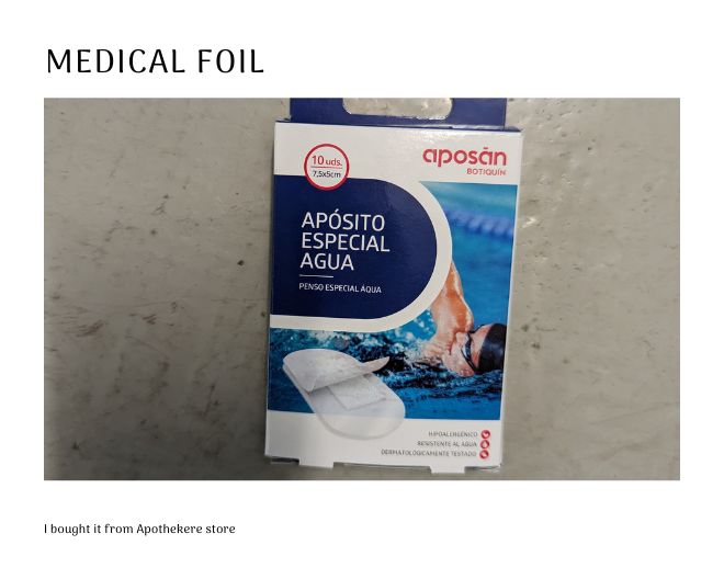
Medical Foil for Skin Sensor
An interesting idea is to use transparent medical foil instead of fabric as the base material for the sensor. This approach creates sensors that are in close proximity to the skin, similar to tattoos.
I purchased this medical foil from a local Apothekere (drug/medicine store) in Barcelona. I also checked with nearby tattoo shops, but unfortunately, they were out of stock. This type of foil is commonly used for skin protection after getting tattoos and is often sold by tattoo shops.
The foil has two layers: a paper backing on the sticky side and a transparent foil on the top side. To use it for creating a sensor, carefully remove the top layer with a pair of tweezers (this may be a bit tricky) and place the Eonyx sensor material onto the exposed adhesive surface. Connect the conductive thread on to the eyonyx material. I eaasentially sandwiched one end of both the conductive threads in between eyonyx tape and the sticky side of medical foil.
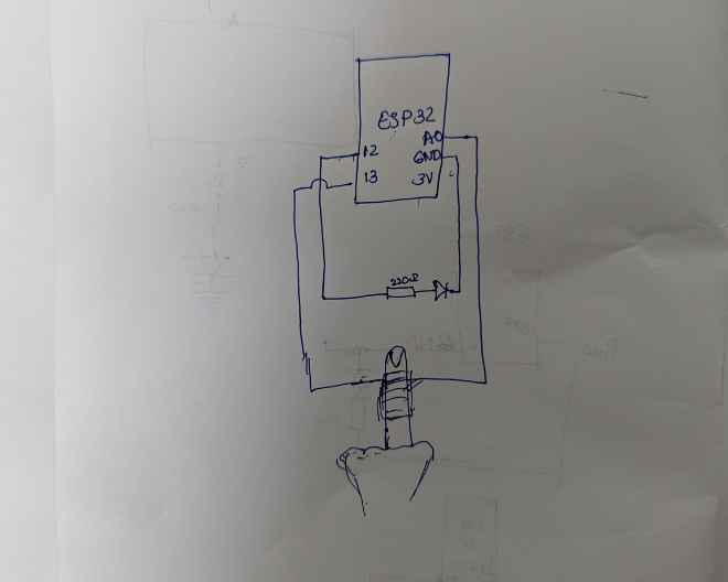
I connected the sensor to the circuit.

The Circuit
void setup() {
// put your setup code here, to run once:
pinMode(A0,INPUT);
pinMode(12,OUTPUT);
Serial.begin(9600);
}
void loop() {
// put your main code here, to run repeatedly:
if(analogRead(A0) > 2000){
digitalWrite(12, HIGH);
}
else{
digitalWrite(12,LOW);
}
Serial.println(analogRead(A0));
delay(100);
}
I also tried to make Fish sensor using copper textile but it didn’t work.
| Qty | Description | Price | Link |
|---|---|---|---|
| 1 | Medical Foil | 4.75 € | Lohmann & Rauscher |
| 1 | Adafruit Huzza32-ESP32 WROM | Lab inventory | |
| 1 | Resistor 220 ohm | Lab inventory | |
| 1 | Resistor 1 kohm | Lab inventory | |
| 1 set | Jumper wires | Lab inventory | |
| 1 | Eonex piece | Lab inventory | |
| 1 | Conductive Thread | Lab inventory | |
| 1 | LED | Lab inventory |