E-textiles
Research
E-textiles, or electronic textiles, encompass fabrics that integrate electronic elements like conductive threads, fibers, or other components to fabricate functional electronic devices. Blending traditional textile materials with modern technology, E-textiles facilitate the evolution of wearable technology, smart fabrics, and other inventive applications. These textiles may incorporate sensors, actuators, and various electronic components, endowing them with responsiveness to environmental conditions and the capability to interact with electronic devices. E-textiles have diverse applications across fields such as fashion, healthcare, sports, and beyond. They serve as fabrics embedded with electronic components, including sensors, chips, batteries, lights, microcontrollers, forming the bedrock of wearable technology and smart clothing. In E-textiles, the selection of fabrics plays a pivotal role in design, often involving manipulation of material resistance to produce varied information outcomes. This is achieved through the creation of distinct structures and layouts using different materials and fabrics.
The distinctive feature of E-textiles lies in the direct embedding of circuits into the textile, enabling individuals to touch, feel, and wear them. This characteristic renders E-textiles versatile translators of diverse information types. They find extensive applications in the medical field, utilized for health monitoring purposes such as tracking vital organs, heart rate, respiratory rate, temperature, and more.
Reference

01 BORI GYOROK
03 Ying Gao
04 Drexel’s interactive projects
05 Kobakant
lecture notes
We had the global lecturel from Liza Stark which was really inspired, start from basic of how electricity works to application, realted projects, here are some basic concept learned from lesson:
Electrical Circuit Basics
Voltage Source: Provides the electrical potential for the circuit (e.g., batteries, power supplies). Conductors: Materials that allow the flow of electric current (e.g., wires). Load/Resistor: A device that consumes electrical energy (e.g., light bulb, motor). Switch: Controls the flow of current by opening or closing the circuit. Current (I), Voltage (V), and Resistance (R):
Current (I): The flow of electric charge measured in Amperes (A). Voltage (V): The electrical potential difference measured in Volts (V). Resistance (R): Opposition to the flow of current measured in Ohms (Ω). Follows Ohm's Law: V = I * R. Ohm's Law:
Describes the relationship between voltage, current, and resistance: V = I * R. Helps calculate one parameter if the other two are known. Series and Parallel Circuits:
Series Circuit: Components are connected in a single path. The same current flows through each component. Parallel Circuit: Components are connected in multiple paths. Voltage is the same across each component.
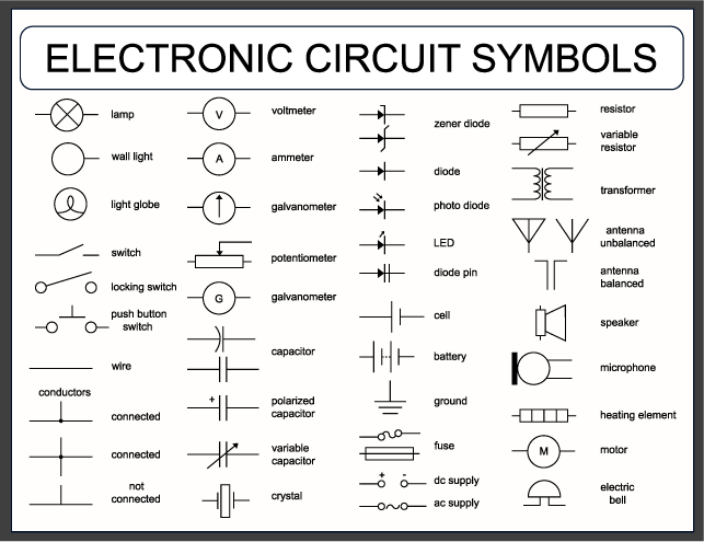
Some basic electrical circuit symbols (source: Adobe stock)
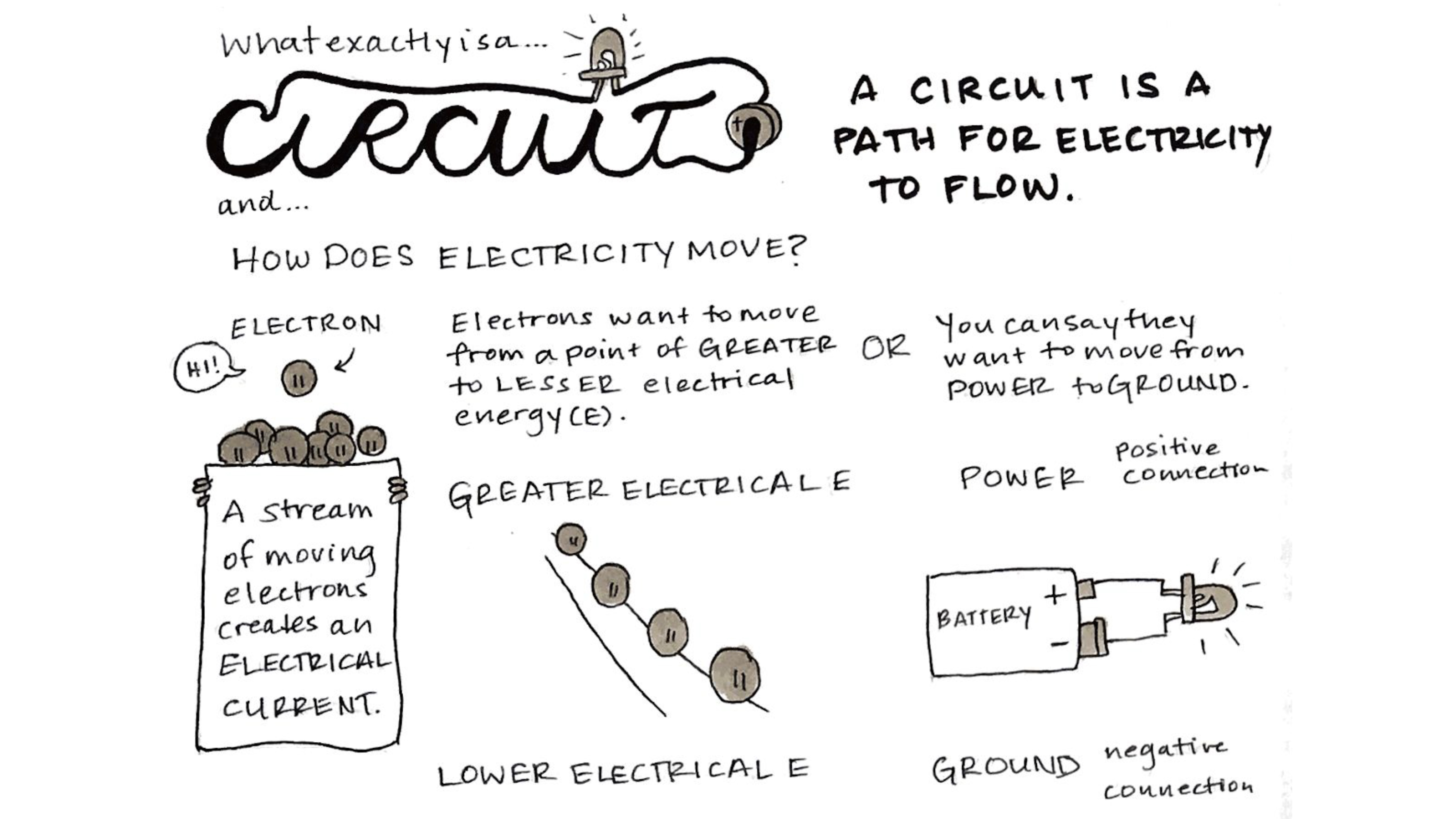
How the circuit works (source: Liza Stark presentation)
Working process
We also had local lecture from Gerard and Citlali Hernández Sánchez They brought us hands on experiment about how to properly connect all components and design circuit, in the same time also assist us work out our assignments.
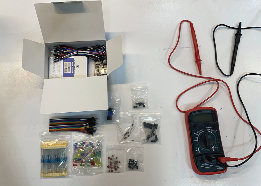
Tools: Electronics fun kit and multimeter
Helpful links: - Arduino
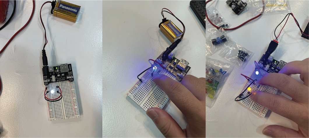
Getting a basic understanding of how to use the Fun Kit, starting from the simplest circuits to incorporating resistors for controlling LEDs and moving on to parallel connections. These will form the foundation for completing the upcoming assignment.
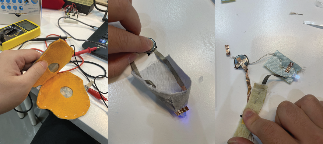
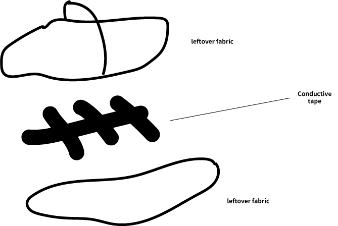
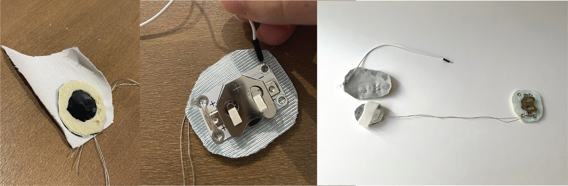
Testing a small digital sensor made using conductive threads, conductive tape, and fabric.
Result
The main concept is to design a finger learning kit utilizing conductive threads and fabric scraps to create both digital and analog sensors. Through two sets of accessories, the pressure movements of the fingers can be translated into a visual (LED) display.
Digital Sensor
int buttonState;

void setup() {
    //put your setup code here, to run once:
  Serial.begin(9600);
  pinMode(D7,INPUT);
}

void loop() {
    //put your main code here, to run repeatedly:

  buttonState=digitalRead(D7);
  Serial.println(buttonState);

}
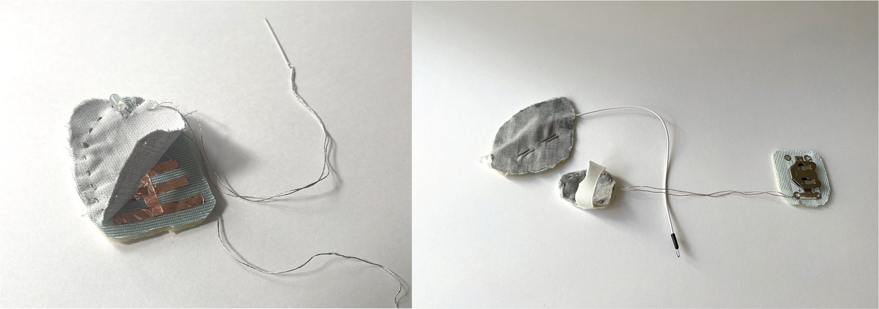
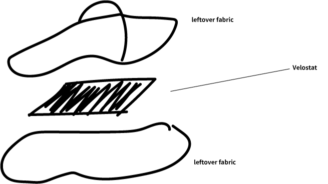
Analog Sensor
const int velostatPin = A0; // Replace with the actual analog pin where the Velostat sensor is connected

void setup() {
  Serial.begin(9600);  // Initialize serial communication
}

void loop() {
  int velostatValue = analogRead(velostatPin); // Read the analog value from the Velostat sensor

  Serial.print("Velostat Value: ");
  Serial.println(velostatValue);

  // You can add conditional checks here based on the analog values to detect specific states or thresholds.

  delay(1000); // Delay for 1 second between readings

}
Would love to explore different analog sensor by changing the behave way such as bending, strectching...etc, a lot of possibilities!