Skin Electronics
Research
Skin electronics encompass electronic devices or components specifically designed to be worn directly on or integrated into the skin. The overarching objective is to develop wearable technology that is discreet, comfortable, and seamlessly integrates with the human body. Key characteristics and components of skin electronics include:
-
1.Flexible and Stretchable: Skin electronics often utilize materials that are flexible and stretchable, allowing them to conform to the skin's contours. This flexibility ensures comfort and facilitates ease of movement, enhancing the wearability of the technology.
-
2.Thin and Lightweight: Typically constructed with thin and lightweight materials, skin electronics aim to minimize any impact on the wearer's comfort. The use of thin, flexible materials also contributes to the overall conformability of the device.
-
3.Biocompatible Materials: Materials chosen for skin electronics prioritize biocompatibility, ensuring prolonged contact with the skin is safe and does not cause irritation or adverse reactions.
-
4.Sensors: Many skin electronics integrate sensors to monitor various physiological parameters, including temperature, humidity, pressure, and bio-signals such as heart rate, muscle activity, or brain waves.
-
5.Wearable Health Monitoring: Skin electronics find applications in health monitoring, providing continuous monitoring of vital signs for real-time health assessment.
-
6.Human-Machine Interfaces: Some skin electronics act as interfaces between the human body and electronic devices, incorporating features such as touch sensors, gesture recognition, or other interactive elements.
-
7.Energy Harvesting: Addressing power requirements, skin electronics may explore energy harvesting methods, such as capturing energy from body movements or temperature differentials.
-
8.Biometric Identification: Skin electronics can be employed for biometric identification, offering a secure and unobtrusive means of identity verification.
-
9.Medical Applications: Beyond monitoring, skin electronics are being developed for medical applications, such as drug delivery patches or electronic skins for prosthetics.
-
10.Integration with Clothing or Accessories: Skin electronics can seamlessly integrate into clothing or wearable accessories, enhancing the overall user experience and ensuring the technology is discreet.
In essence, the development of skin electronics involves interdisciplinary collaboration, bringing together expertise in materials science, electronics, and biomedical engineering to create devices that seamlessly merge with the human body. These technologies present new possibilities in healthcare, communication, and human-computer interaction.
The image from Katia Vega's global lecture presentation clearly explained the concept of on body technology
Reference
02 Martin Weigel team at Saarland University in Saarbrücken, Germany
03 Researchers from the University of Tokyo's Graduate School of Engineering
05 Duoskin, MIT
Process and workflow
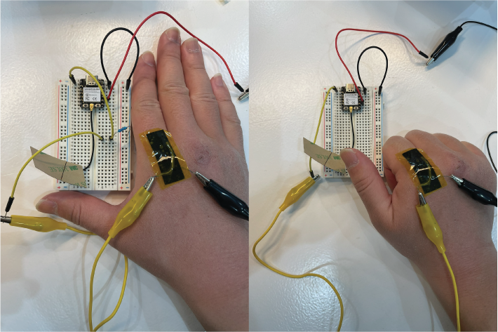
We had some experiments with Citlali We made both skin pressure sensors and a skin matrix, to understand the principle of working with our skin, through these experiments, we found out there are a lot of possibilities could be explore.
Skin Sensor
Required materials:
- Conductive thread
- Skin-safe double sided tape
- Velostat/eontex
- Kapton tape
The sketch shows how to palce all the materials.
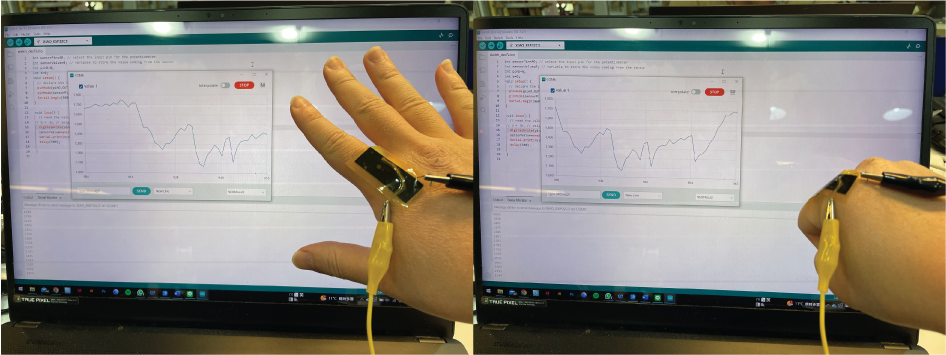
The resistance was changing based on the degree of bending of my fingers.
After determining the resistance, we connect it to the Arduino by selecting one of the resistance values as the reference resistor. This allows us to read the values displayed on the monitor and subsequently test various resistors to identify the ones providing the broadest reading ranges. These codes enable us to read data by bending our fingers.
int sensorPin=A0; // select the input pin for the potentiometer
int sensorValue=0; // variable to store the value coming from the sensor
int pinD=8;
int b=0;
void setup() {
  // declare the ledPin as an OUTPUT:
  pinMode(pinD,OUTPUT);
  pinMode(sensorPin,INPUT);
  Serial.begin(9600);
}

void loop() {
  // read the value from the sensor:
// b = !b; // asigno el contrario
  digitalWrite(pinD,HIGH);
  sensorValue=analogRead(sensorPin);
  Serial.println(sensorValue);
  delay(500);

}
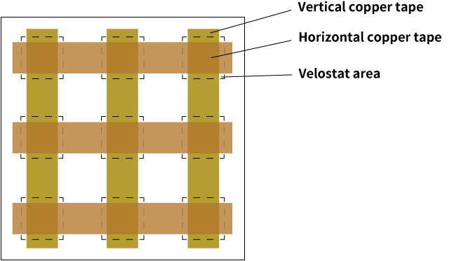
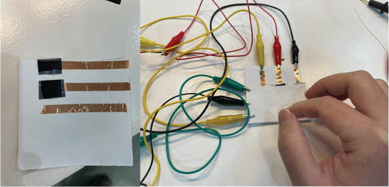
Skin matrix sensor
After grasping the functionality of the pressure sensor, Citlali guided us in constructing a 3x3 matrix with 9 sensor reading points.
Required materials:
- Tracing paper
- Copper tape
- Velostat
- 3 x 1k ohm resistor
- The surface which can place circuit(in this case we use white paper)
The structure graphic shows how the units assemable.
Code for reading the matrix values as an array from 0-8
//3x3 Matrix using Copper Tape and Velostat
//Each Analog Input
//+ 220 ohms Resistor  // The resistor depends on the resistivity of the sensor


#define numRows 3  // Constant variable
#define numCols 3
#define sensorPoints numRows* numCols

int rows[] = { A0, A1, A2 };
int cols[] = { 8, 9, 10 };
int incomingValues[sensorPoints] = {};

void setup() {
  for (int i = 0; i < numRows; i++) {
    pinMode(rows[i], INPUT);
  }
  for (int i = 0; i < numCols; i++) {
    pinMode(cols[i], OUTPUT);
  }
  Serial.begin(9600);
}

void loop() {
  for (int colCount = 0; colCount < numCols; colCount++) {
    digitalWrite(cols[colCount], HIGH);  //5v
    for (int rowCount = 0; rowCount < numRows; rowCount++) {
      incomingValues[colCount * numRows + rowCount] = analogRead(rows[rowCount]);  // read INPUT
    }                                                                              // end row Count

    digitalWrite(cols[colCount], LOW);  // set back to LOW 0v (-)
  }                                     // end colCount

  // Print the incoming values of the grid:
  for (int i = 0; i < sensorPoints; i++) {
    Serial.print(incomingValues[i]);
    if (i < sensorPoints - 1)
      Serial.print("\t");
  }
  Serial.println();
  delay(10);
}
Code for Skin matrix sensor visulaisation in Processing
/*
Code based on Tom Igoe’s Serial Graphing Sketch
 >> http://wiki.processing.org/w/Tom_Igoe_Interview
 Reads X analog inputs and visualizes them by drawing a grid
 using grayscale shading of each square to represent sensor value.
 >> http://howtogetwhatyouwant.at/
 */

import processing.serial.*;

Serial myPort; // The serial port
int rows = 3;
int cols = 3;
int maxNumberOfSensors = rows*cols;
float[] sensorValue = new float[maxNumberOfSensors]; // global variable for storing mapped sensor values
float[] previousValue = new float[maxNumberOfSensors]; // array of previous values
int rectSize = 0;
int rectY;
void setup () {
  size(600, 600); // set up the window to whatever size you want
  rectSize = width/rows;

  println(Serial.list()); // List all the available serial ports
  String portName = Serial.list()[2]; // set the number of your serial port!
  myPort = new Serial(this, portName, 9600);
  myPort.clear();
  myPort.bufferUntil('\n'); // don’t generate a serialEvent() until you get a newline (\n) byte
  background(255); // set inital background
  smooth(); // turn on antialiasing
  rectMode(CORNER);
}

void draw () {
  for (int i = 0; i < maxNumberOfSensors; i++) {
    fill(sensorValue[i]);
    rect(rectSize * (i%rows), rectY, rectSize, rectSize); //top left
    if ((i+1) % rows == 0) rectY += rectSize;
  }
  rectY=0;
}

void serialEvent(Serial myPort) {
  String inString = myPort.readStringUntil('\n'); // get the ASCII string
  println("test");
  if (inString != null) { // if it’s not empty
    inString = trim(inString); // trim off any whitespace
    int incomingValues[] = int(split(inString, "\t")); // convert to an array of ints

    if (incomingValues.length <= maxNumberOfSensors && incomingValues.length > 0) {
      for (int i = 0; i < incomingValues.length; i++) {
        println("Raw sensor value: " + incomingValues[i]);
        sensorValue[i] = map(incomingValues[i], 255, 1000, 255, 255);
        println("Mapped sensor value: " + sensorValue[i]);
      }
    }
  }
}
Lights up through skin graphic
My idea is to overlay conductive materials on my skin through geometric designs, showcasing a clean and powerful aesthetic. Then, using velostat as a pressure-sensing medium, I aim to create LED illumination that appears to change in brightness with the rhythm of breathing.
Start from geometrical simple arrangement.
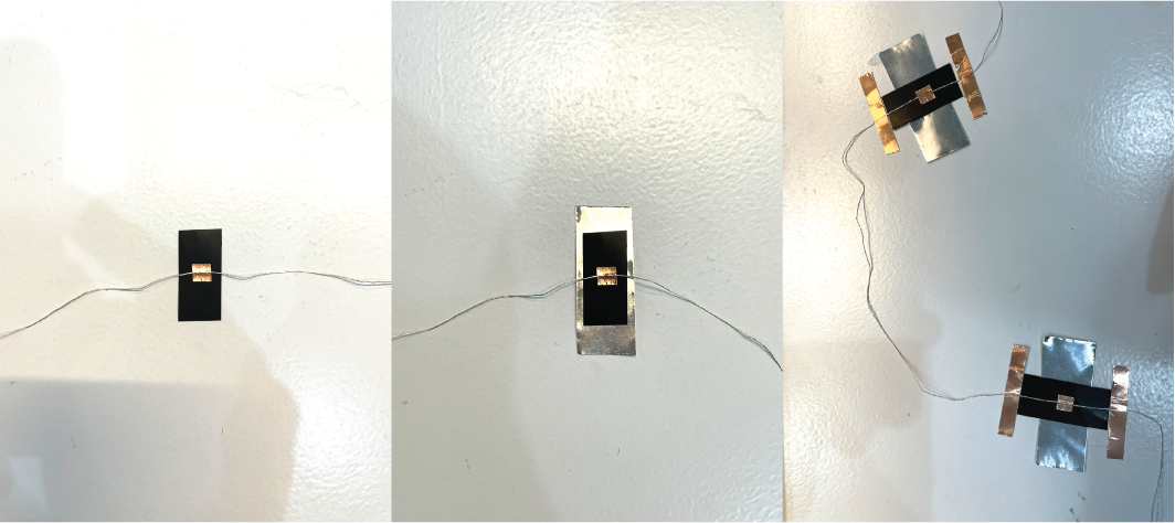
Play the material arrangement on the skin.
How does it work.
Conclusion
Unlike wearable electronic devices, skin electronics have a more direct correlation and relationship with the human skin and physiology. Consider the human body as the largest biological material medium; all physiological responses could potentially serve as sensors to drive electronic devices. This is such a fascinating field to explore, and in the future, there is an opportunity to further extend the content of this week for ongoing development.