5. E-textiles
Understanding Basics
Throughout this week, I have been introduced and come across many different inspiring projects. This week's focus for me was to understand the soft switcehs and get a better understanding on how to write some code more than creating a final done and aesthetic piece. After the global lecture, we had two local lectures: one by Gerard and one by Citlali Hernández Sánchez. Both lecturers were very inspiring and they showed us how to create and use a digital and analog sensor.
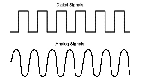
"The difference between analog and digital technologies is that in analog technology, information is translated into electric pulses of varying amplitude. In digital technology, translation of information is into binary format (zero or one) where each bit is representative of two distinct amplitudes."
With Gerard we were able to create a circuit on our breadboards, connect an LED, understand resistance, and turn it on and off with a button.
Circuit
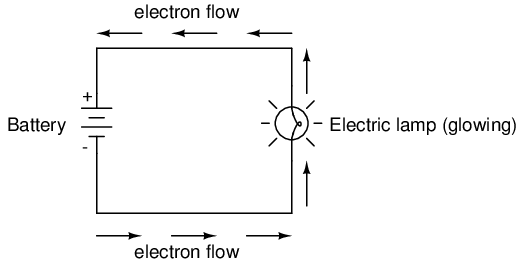
An electric circuit is a closed loop of components that allow the electrons to pass through.
Breadboard
A breadboard is the circuit building platform, you connect the components on it without soldering. It has rows for the power and the ground on either end and then has rows of 5. These series of 5 are connected to one another so anything placed in one will be translated into all 5.
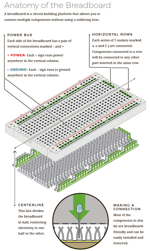
image source SparkFun Education by Megan Hemmings
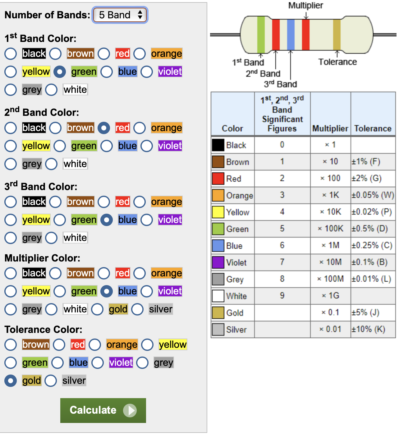
Resistors
A resistor implements electrical resistance in a circuit, like reducing the flow of electrons. To understand which resistors to use in our LED circuits we used the calculator below.
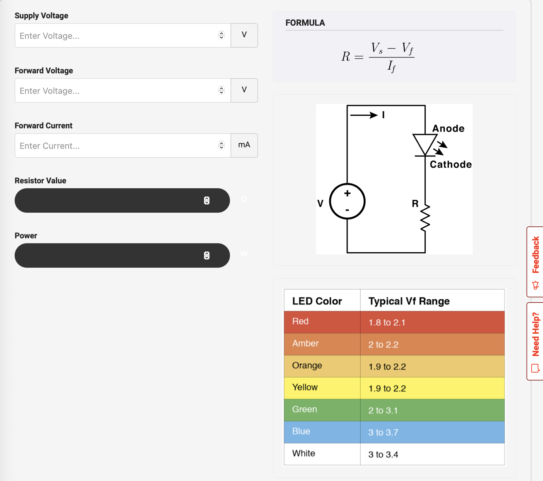
Also, you are able to find out which resistor you are using if it is not labeled by using this calculator.
Digital Sensor
First part of the week we started by understanding how to create digital snesor. We started by understanding how LEDs can be connected, then understanding the use of resistors, adding a potentiometer, and then moving on to creating soft switched. A switch with textiles and conductive thread.
Works
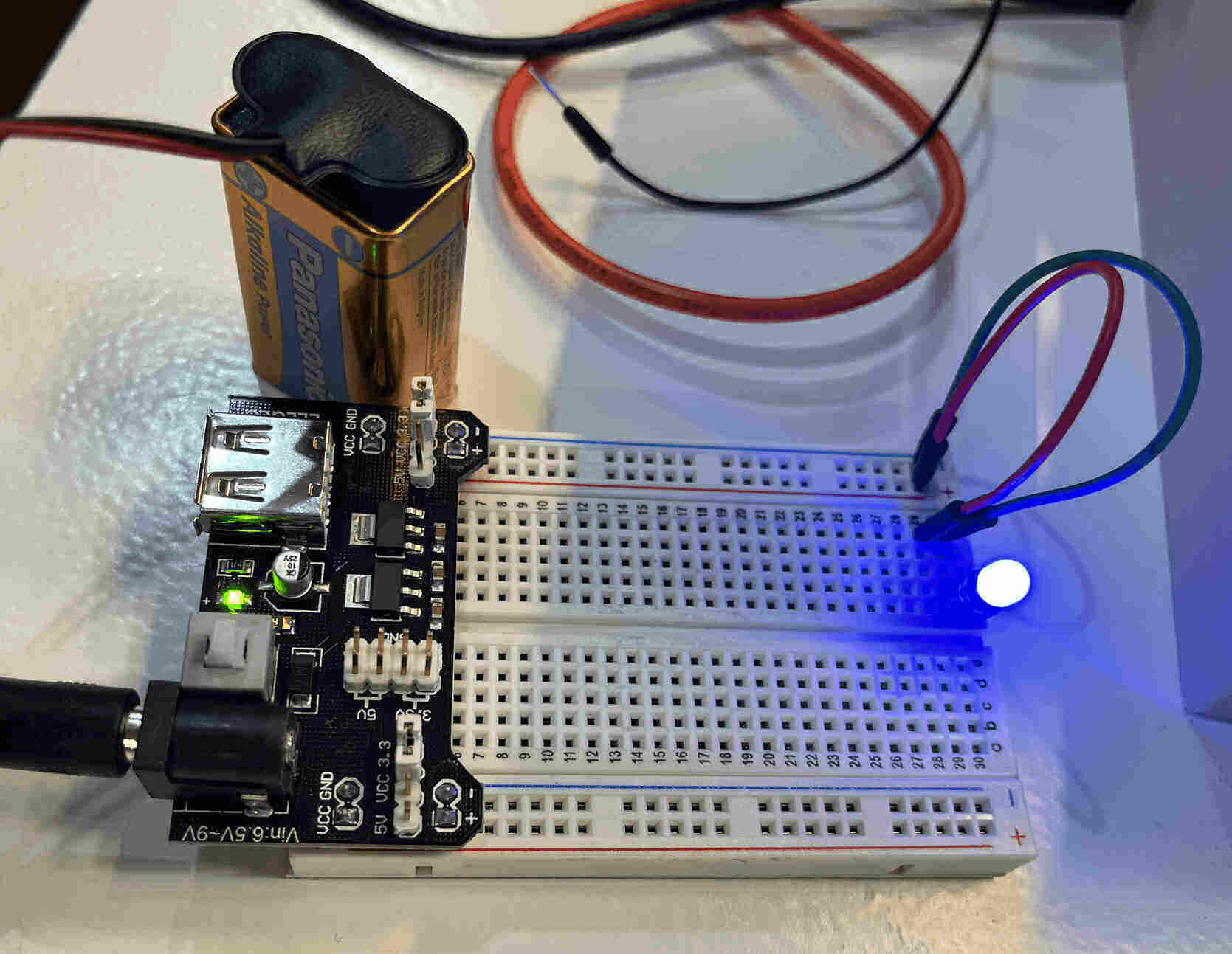
First step was to understand how to connect an LED to the board.
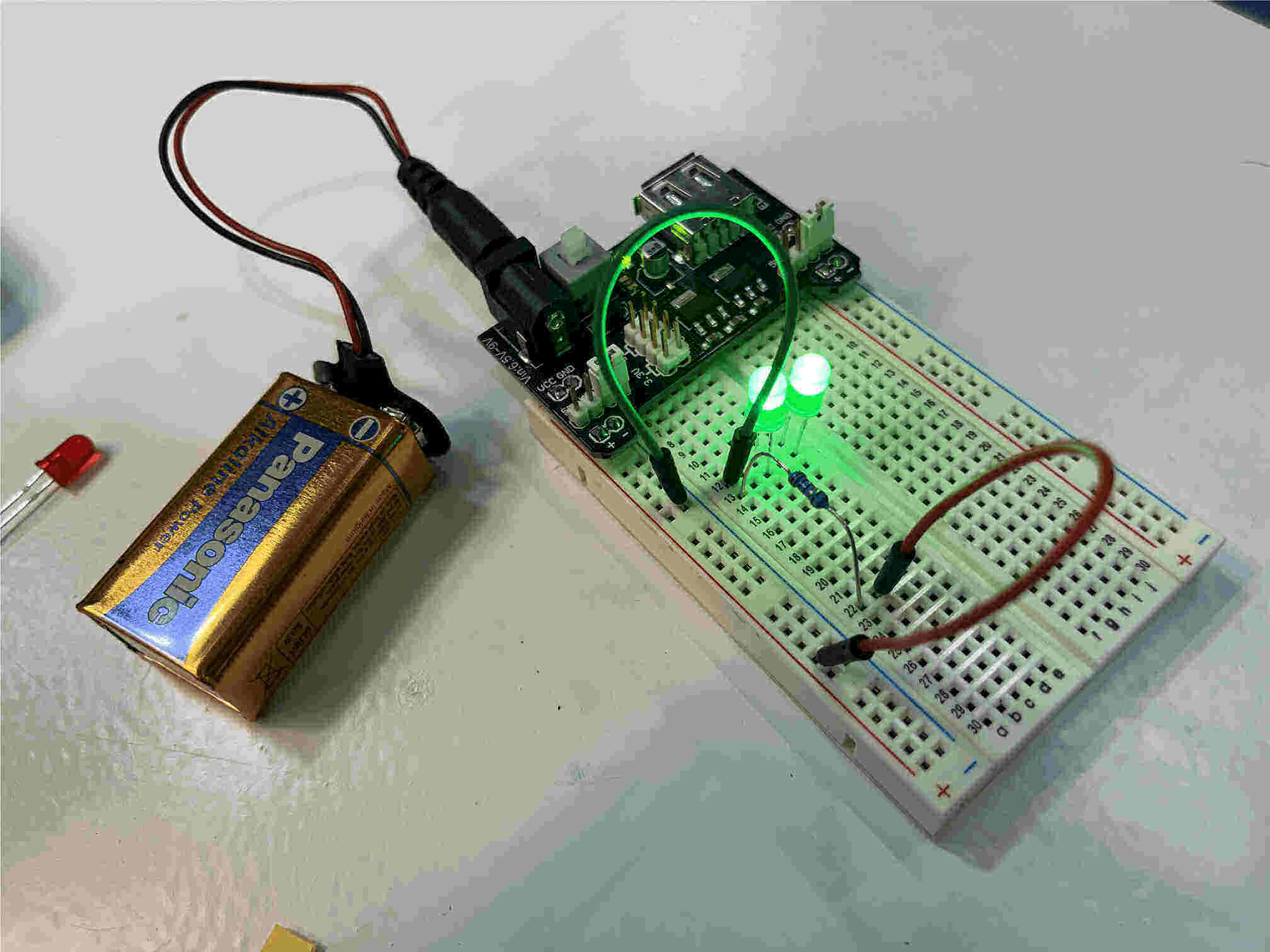
Then tested adding a resistor and adding two LEDs in parallel.
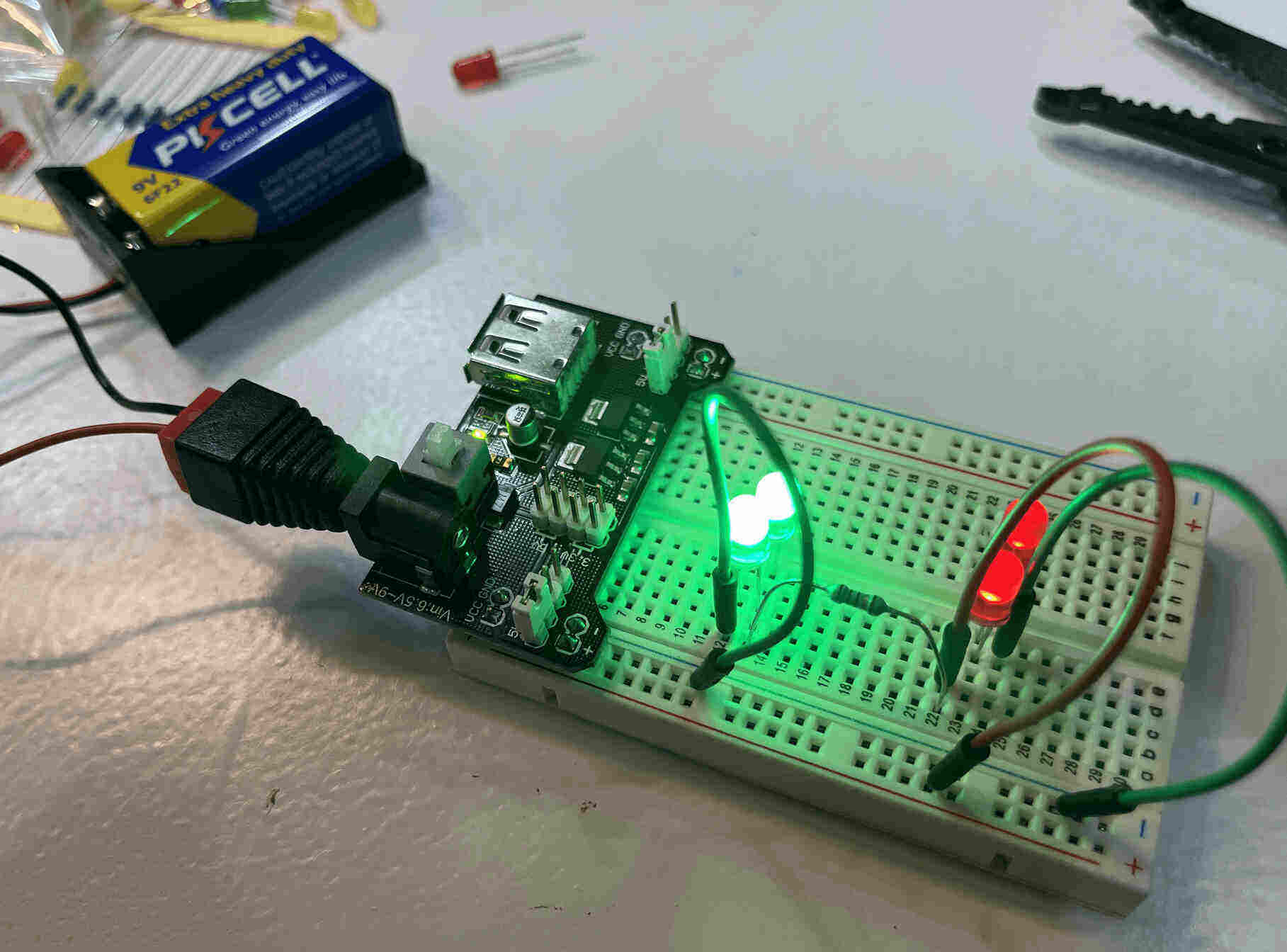
Testing one in parallel and one in series. It shows how much the one in series is dimmed.
Then I wanted to try using the RGB LED. It is one LED that has 4 different pins, R, GND, G, and B. There are two types, one where the longest pin (the second) is a cathode and one where its an anode. Ours was a cathode.
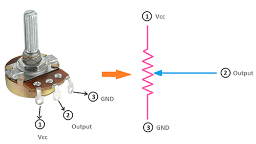
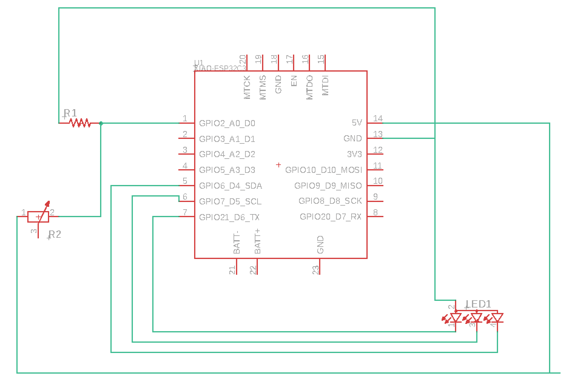
After trying that, I tested it out with a potentiometer. Its always good practice to check the schematics online to know where to connect all the pins.
Digital Sensor
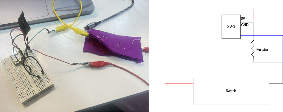
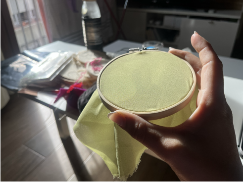
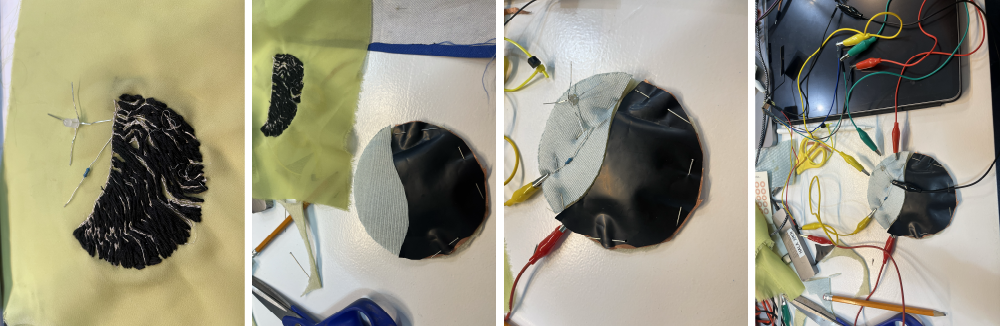
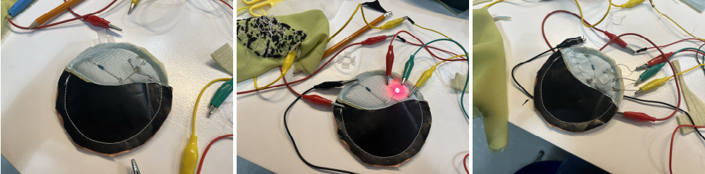
We began designing our switch. I decided to use conductive thread on neoprene.
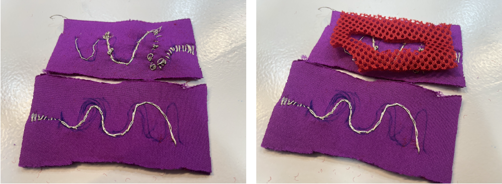
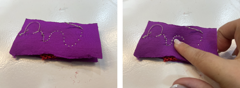
In the above sample switch, I used scrap purple fabric, a thick sponge mesh, and conductive thread. When the switch is pressed, the conductive thread on either end touch each other and the circuit closes.
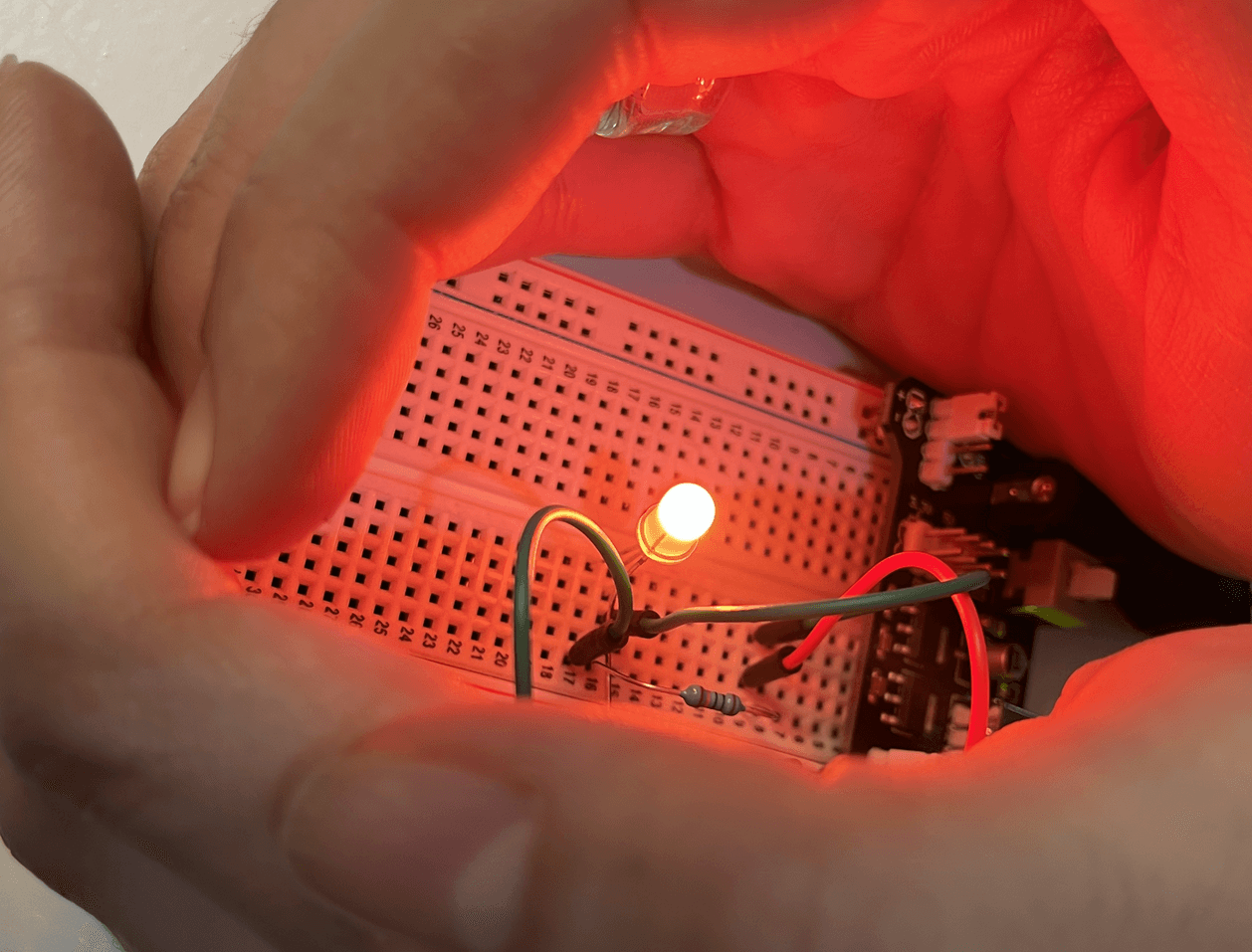
Below you will see how the sample is then used as a switch to turn on and off an LED.
XIAO
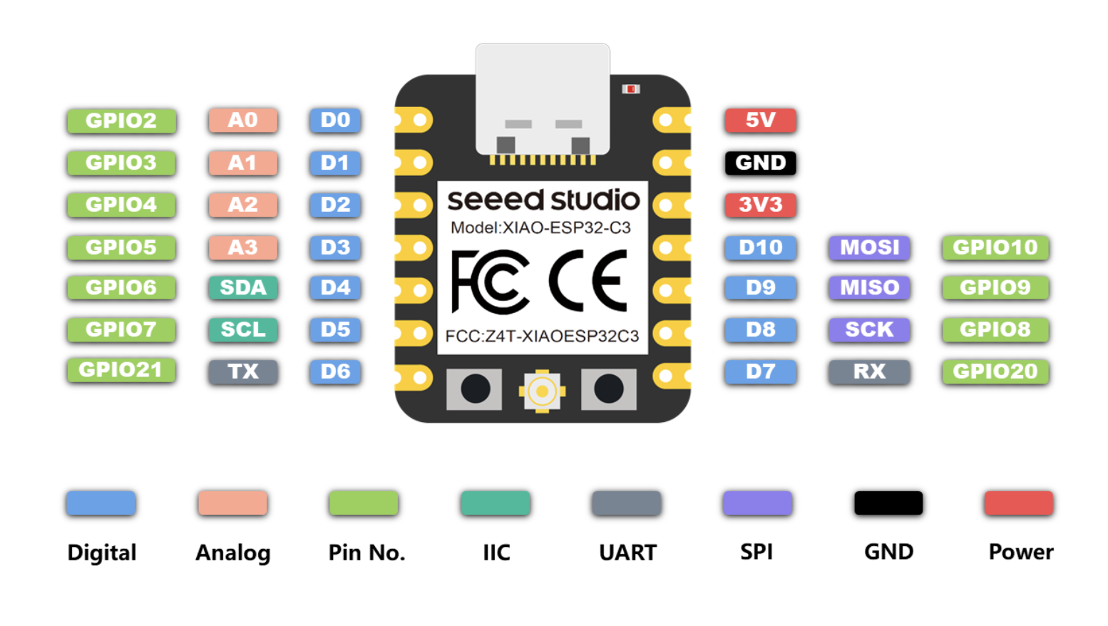
Citlali showed us how to use the XIAO - ESP32C3 to digital and analog read and write.
The XIAO is a mini computer that we then used to talk to the components and connect the inputs to outputs with a way for us to read it as well.
Looking at the pinout diagram, we see that it supplies 5V and 3.3V, has ground, has 11 digital pins, and 4 of which can also be used as analog pins.
int buttonState;

void setup() {
  Serial.begin(9600);
  pinMode(D7,INPUT); // Enable the internal pull-up resistor
}

void loop() {
  buttonState=digitalRead(D7);
  Serial.println(buttonState);

}
Digital Switch to LED
int ledPin = D6;   // LED connected to GPIO pin 2
int buttonState;
int ledState = LOW;     // Track the LED state

void setup() {
  Serial.begin(9600);
  pinMode(D6, OUTPUT);
  pinMode(D7, INPUT_PULLUP); // Enable the internal pull-up resistor
}

void loop() {
  int switchState = digitalRead(D7);

  if (switchState == LOW) {
    // Button is pressed, toggle the LED state
    ledState = !ledState;
    digitalWrite(ledPin, ledState);
    delay(100); // Debounce the button
  }
}
Trial of RGB LED Color Changing
Materials Used
- XIAO
- RGB LED
- Conductive Thread
- Scrap Fabric
- Scrap Mesh Spacer
Digital Sensor // Key Chain
I crochet a long key chain holder that would be a necklace and would have a light at the edge where the keys hang. When that part is squeezed together, the light will turn on illuminating the way or the key hole.
The materials used for the keychain is the cotton yarn, a coin battery, battery holder, insulating thick fabric, conductive thread, and an LED.

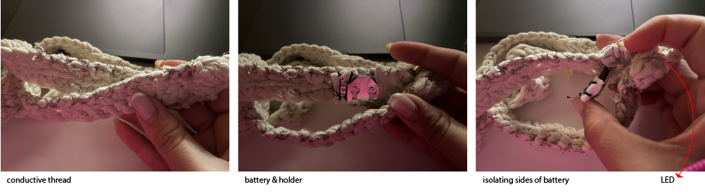
Materials Used
- 3V Coin Battery
- Battery Holder
- White LED
- Conductive Threaf
- Yarn
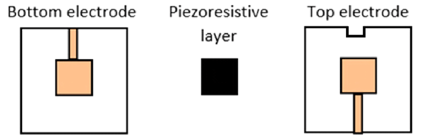
Analog Sensor
Using the same sensor as the digital, I added a velostat between the layers and then changed the code so I can read the values that were given by the analog switch.
A velostat is pressure sensitive and its resistance changes with pressure. The more pressure the less the resistance.
const int velostatPin = A0; // Replace with the actual analog pin where the Velostat sensor is connected

void setup() {
  Serial.begin(9600);  // Initialize serial communication
}

void loop() {
  int velostatValue = analogRead(velostatPin); // Read the analog value from the Velostat sensor

  Serial.print("Velostat Value: ");
  Serial.println(velostatValue);

  // You can add conditional checks here based on the analog values to detect specific states or thresholds.

  delay(1000); // Delay for 1 second between readings
}
void setup() {
  Serial.begin(9600);
}

void loop() {
  int y1 = analogRead(A0);
  Serial.println(y1);  // values between 0 and 1023
  delay(100);
}
Changing Color
void setup() {
pinMode(redPin, OUTPUT);
pinMode(greenPin, OUTPUT);
pinMode(bluePin, OUTPUT);
}

void loop() {
// Fade in red
for (int i = 0; i < 256; i++) {
    analogWrite(redPin, i);
    delay(10);
}

for (int i = 255; i >= 0; i--) {
    analogWrite(redPin, i);
    delay(10);
}

for (int i = 0; i < 256; i++) {
    analogWrite(greenPin, i);
    delay(10);
}

for (int i = 255; i >= 0; i--) {
    analogWrite(greenPin, i);
    delay(10);
}

for (int i = 0; i < 256; i++) {
    analogWrite(redPin, i);
    analogWrite(bluePin, i);
    delay(10);
}
}
Materials Used
- XIAO
- RGB LED
- Resistor
- Conductive Thread
- Velostat
- Scrap Fabric
- Scrap Mesh Spacer
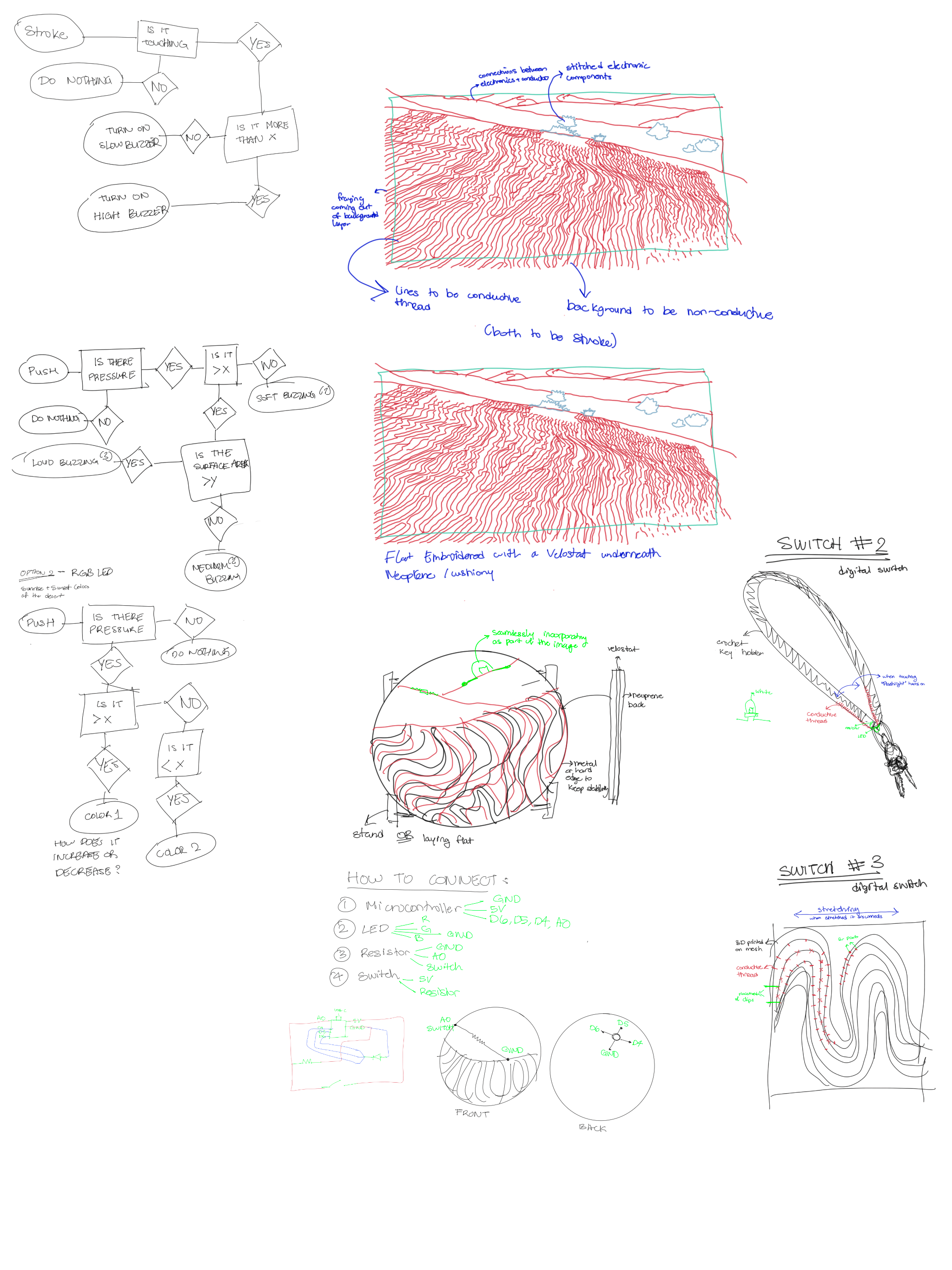
Project
To clear out my thoughts, I began with ideation. I drew out some flow charts and quick sketches of what I wanted my piece to be.
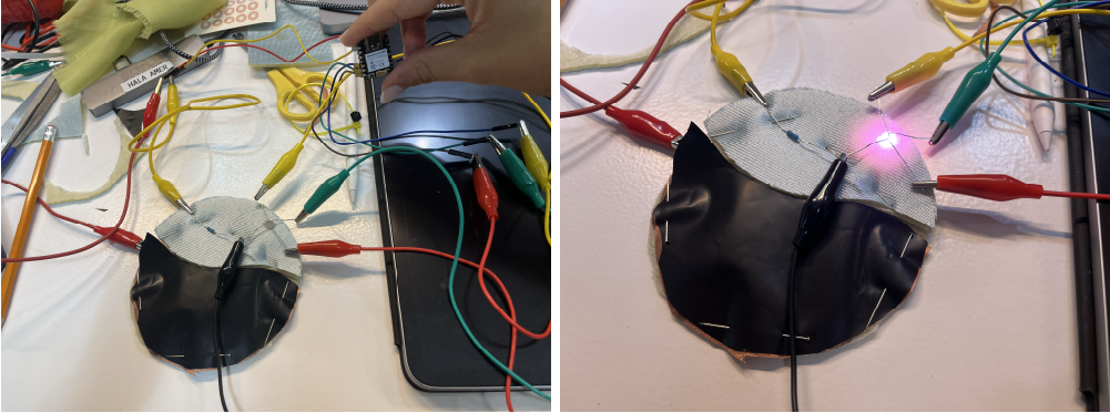
After putting everything together, I plugged in the XIAO to test the fading of colors. It did not work, there were only two colors blinking. After step by step investigation, I found two problems:
-
The G and B alligator clips were flipped (g plugged in b and vice versa). Upon fixing it, it was still giving the wrong color values.
-
The LED did not have any resistors attached. Since the LED was not giving me any of the correct colors, I deduced that the issue must have been with the resistors. It was working but the light must have burned out with tume. I got a new LED and added some resistors to each leg and tested the colors, they were working again.
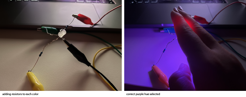
So the solution is to remove all the components from the neoprene and resew the ned LED with the resistors.
Materials Used
- XIAO
- RGB LED
- Resistor
- Conductive Thread
- Velostat
- Scrap Fabric
- Wool Spacer
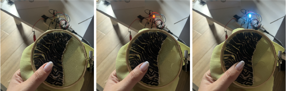
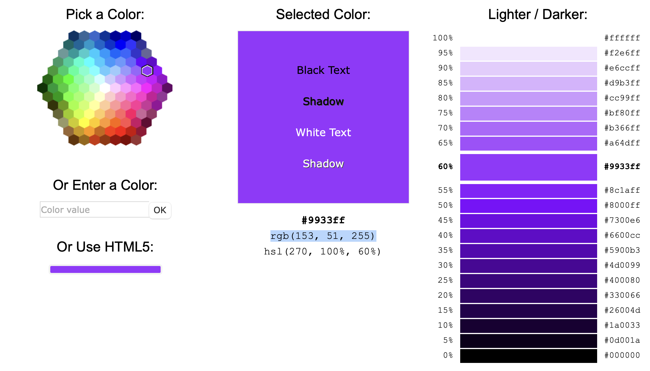
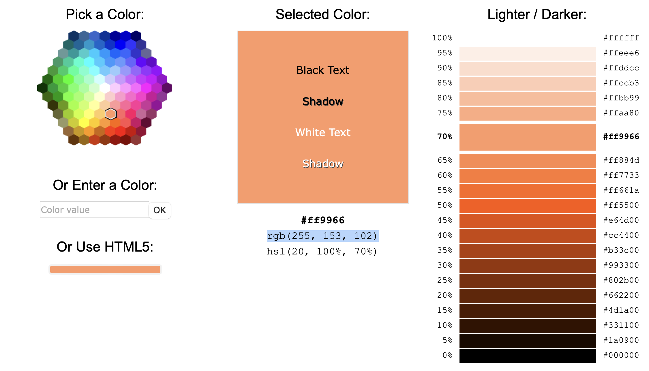
Color Selection
I selected the colors I wanted the fade to be by using the HTML Color Picker by W3Schools.
The colors I selected were to represent a sunrise and sunset.
Color Dimming Trial
const int redPin = D6;    // Connect the red pin of the RGB LED to digital pin 9
const int greenPin = D5;  // Connect the green pin of the RGB LED to digital pin 10
const int bluePin = D4;   // Connect the blue pin of the RGB LED to digital pin 11

void setup() {
pinMode(redPin, OUTPUT);
pinMode(greenPin, OUTPUT);
pinMode(bluePin, OUTPUT);
}

void loop() {
for (int i = 0; i < 256; i++) {
    analogWrite(redPin, 153);
    analogWrite(greenPin, 51);
    analogWrite(bluePin, 255);
    delay(10);
}
for (int i = 255; i >= 0; i--) {
    analogWrite(redPin, 153);
    analogWrite(greenPin, 51);
    analogWrite(bluePin, 255);
    delay(10);
}
for (int i = 0; i < 256; i++) {
    analogWrite(redPin, 255);
    analogWrite(greenPin, 153);
    analogWrite(bluePin, 102);
    delay(10);
}
for (int i = 255; i >= 0; i--) {
    analogWrite(redPin, 255);
    analogWrite(greenPin, 153);
    analogWrite(bluePin, 102);
    delay(10);
}
}
Code that worked... for a while.
const int sensorPin = A0;  // Analog pin where the sensor is connected
const int redLED = D6;     // Digital pin where the LED is connected
const int greenLED = D5;   // Digital pin where the LED is connected
const int blueLED = D4;    // Digital pin where the LED is connected

void setup() {
pinMode(sensorPin, INPUT);
pinMode(redLED, OUTPUT);
pinMode(greenLED, OUTPUT);
pinMode(blueLED, OUTPUT);
Serial.begin(9600);  // Initialize serial communication for debugging
}

void loop() {
// Read the analog value from the sensor
int sensorValue = analogRead(sensorPin);

// Map the sensor value to the LED brightness (0 to 255)
int brightness = map(sensorValue, 0, 1023, 0, 255);

// Smoothly fade the LED brightness
fadeRedLED(brightness, 3000);    // Adjust the fading duration as needed
fadeGreenLED(brightness, 3000);  // Adjust the fading duration as needed
fadeBlueLED(brightness, 3000);   // Adjust the fading duration as needed


// Print the sensor value and brightness to the serial monitor
Serial.print("Sensor Value: ");
Serial.print(sensorValue);
Serial.print("   Brightness: ");
Serial.println(brightness);

delay(100);  // Add a short delay for stability
}

void fadeRedLED(int targetBrightness, int duration) {
int currentBrightness = analogRead(redLED);
int step = (targetBrightness - currentBrightness) / duration;
for (int i = 0; i < duration; i++) {
    currentBrightness += step;
    analogWrite(redLED, currentBrightness);
    delay(1);
}
// Ensure the LED reaches the target brightness
analogWrite(redLED, targetBrightness);
}
void fadeGreenLED(int targetBrightness, int duration) {
int currentBrightness = analogRead(greenLED);
int step = (targetBrightness - currentBrightness) / duration;
for (int i = 0; i < duration; i++) {
    currentBrightness += step;
    analogWrite(greenLED, currentBrightness);
    delay(1);
}
// Ensure the LED reaches the target brightness
analogWrite(greenLED, targetBrightness);
}
void fadeBlueLED(int targetBrightness, int duration) {
int currentBrightness = analogRead(blueLED);
int step = (targetBrightness - currentBrightness) / duration;
for (int i = 0; i < duration; i++) {
    currentBrightness += step;
    analogWrite(blueLED, currentBrightness);
    delay(1);
}
// Ensure the LED reaches the target brightness
analogWrite(blueLED, targetBrightness);
}
Troubleshooting the fading with the values.
Code for the above:
```c int redPin = D6; // Pin conectado al ánodo o cátodo del LED rojo int greenPin = D5; // Pin conectado al ánodo o cátodo del LED verde int bluePin = D4; // Pin conectado al ánodo o cátodo del LED azul int delayTime = 1000; // Tiempo de retardo entre pasos de fundido const int sensorPin = A0; // Analog pin where the sensor is connected
void setup() { pinMode(sensorPin, INPUT); pinMode(redPin, OUTPUT); pinMode(greenPin, OUTPUT); pinMode(bluePin, OUTPUT); Serial.begin(9600); // Initialize serial communication for debugging }
void loop() { int y1 = analogRead(A0); Serial.println(y1); // int sensorValue = analogRead(sensorPin); // int brightness = map(sensorValue, 0, 1023, 0, 255); // Serial.println("Sensor Value: "); // Serial.println(sensorValue); // Serial.println(" Brightness: "); // Serial.println(brightness); // pink to orange if (y1 > 100 && y1 <= 300) { fadeToColor(255, 255, 0, 255, 140, 0, 7000); } // orange to yellow else if (y1 > 300 && y1 < 600) { fadeToColor(255, 140, 0, 255, 105, 180, 7000); } // yellow to purple else if (y1 >= 600) { fadeToColor(255, 105, 180, 128, 0, 128, 7000); } else { analogWrite(redPin, 0); analogWrite(greenPin, 0); analogWrite(bluePin, 0); } }
void fadeToColor(int startR, int startG, int startB, int endR, int endG, int endB, int duration) { int steps = duration / delayTime; float deltaR = (endR - startR) / steps; float deltaG = (endG - startG) / steps; float deltaB = (endB - startB) / steps;
for (int i = 0; i < steps; i++) { analogWrite(redPin, startR + i * deltaR); analogWrite(greenPin, startG + i * deltaG); analogWrite(bluePin, startB + i * deltaB); //delay(delayTime); delay(1000); } }
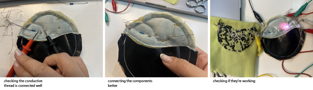
I had to resew all the connections since they weren't working for a while.
My Friend for the Week // ChatGPT
I tried to first write down the code that I know and then ask Chat if it would work and if it needs fixing. Then I would ask it to explain every line of code it added for me.