8. Wearables
During this week I was in Shanghai, China for the opening of an exhibition and the Shanghai Design Week. I will be pulling from future weeks to showcase my understanding of Wearable devices and technologies.
| Actuators | A component of a circuit that moves or controls another part based on input |
| Visla Approaches | LEDs, Neopixels, Fiber Optics, Thermochromic Ink |
| Sound Approaches | Speakers, Electromagnets |
| Motion | Shape Memory Alloys, Flip Dots, Vibration Motors/Haptics |
Capacitive Sensors, Conductive Ink
Used in Week12: Skin Electronics.
What is a Capacitor Sensor?
A capacitive sensor functions by detecting altering capacitance of a nearby object. When there is an applied electric field, the capacitance of the object changes. The sensor then measures this change in the capacitance and reports it back to a receiver. If the electric field is removed, then the capacitance of the object decreases. The sensor then reports that decrease to the receiver. The receivers use this information to determine the change in capacitance based on the time of the change. They are sensitive and easily affected by other elements like temperature and humidity.
The ink used in these explorations is Bare Conductive which is a skin safe conductive ink.
To create a capactive sensor with the electric paint, the tutorial uses two digital pins (4 and 2) with a 1M Ohm resistor between them. Pin 2 is directly connected to the sensor (electric paint). Once you come closer to the electric paint, the values shoot up and when you are further away they are smaller. Similar to a proximity sensor.
I then painted a square on tape and cut it out and placed it on cling film to wrap it around my arm and see how the ranges changed. Because it is touching the skin, maybe from the heat of the skin, the values are already quite high and the LED is always on.
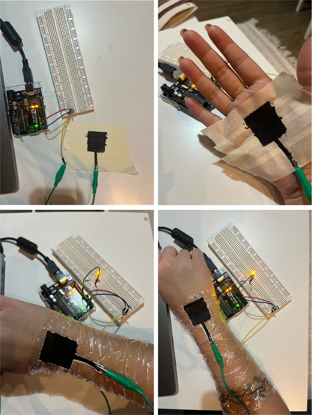
 I then added the long wavy line to connect the pin to the square and wrapped the cling film around my arm more securely. I noticed that with this sensor I'm able to see changes in the value while approaching the ink, with added pressure, and with movement.
Values:
- Proximity: if my arm is laying flat on a surface the values are around 30 and then with approaching it with my other hand they go up to 200s.
- Pressure: with my arm laying flat on a suface the values are around 30 and when pressing with my other hand on top of the square and some of the line the values jump up to 700.
- Movement: as I move my hand and fingers and rotate my wrist, the cling film and ink touches my skin at different points and when it does the values vary from 0 to 200.
Taking it one step at a time, I now tried moving the LED onto my hand as well and finding ways to connect it to the arduino. I made the LED and resistor into a ring and used the solder to wrap it around the connections to hold them together and to the jumper wires. Next step is to figure out how to extend the connections and attach the microcontroller to my arm as well.
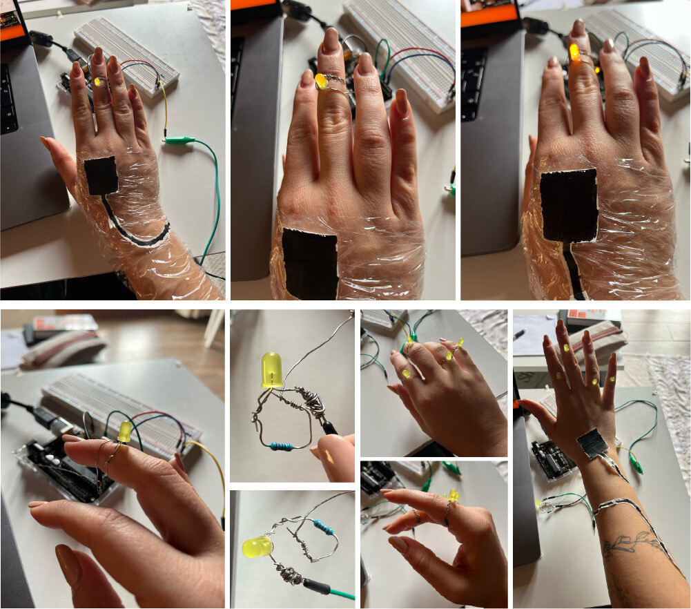
I began attaching the rings to the rest of the circuit. I attached the solder from the front to the pin jumper wire. The ground was attached from the palms using the electric paint and wrapped around the arm following the paths.

Connections

Code for the Capacitor Sensor to turn on LED after a specific threshold.
#include <CapacitiveSensor.h>
int ledPin = 9;
const int threshold = 10000;
CapacitiveSensor sensor = CapacitiveSensor(4, 2);  // 1M resistor between pins 4 & 2, pin 2 is sensor pin

void setup() {
  Serial.begin(115200);
}

void loop() {
  long measurement = sensor.capacitiveSensor(30);
  Serial.println(measurement);
  delay(100);
  if (measurement > threshold) {
    ledPin = map(measurement, 0, 1023, 0, 255);
    analogWrite(9, ledPin);
  } else {
    analogWrite(9, 0);
  }
}
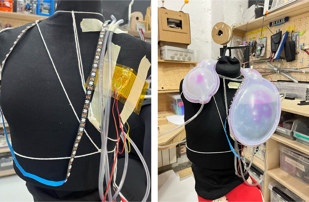
LED Strip, Neopixels
Used in Week10: Open Source Hardware, Photobioreactor.
Tools Used:
- Arduino Uno, R3
- LED Strip
- Neopixel library for Arduion IDE
- Photoresistor
Using a photoresistor and an LED strip to make sure the Algae has the correct luminosity at all stages.

#include <Adafruit_NeoPixel.h>
#define pResistor_pin A2  // Photoresistor
#define LED_PIN 9         // LED strip
// Defining LED constant
#define LED_COUNT 60


int luminosity;     // Store value from photoresistor (0-1023)
int setpoint = 45;  // Set your desired temperature in Celsius
int Vo;


Adafruit_NeoPixel strip(LED_COUNT, LED_PIN, NEO_GRB + NEO_KHZ800);


void setup() {
 Serial.begin(9600);
 pinMode(pResistor_pin, INPUT);
 strip.begin();
 strip.show();
}


void loop() {
 luminosity = analogRead(pResistor_pin);
 static unsigned long previousMillis = 0;
 const unsigned long interval = 5000;
 unsigned long currentMillis = millis();
 if (currentMillis - previousMillis >= interval) {
   previousMillis = currentMillis;
   Serial.print("Luminosity: ");
   Serial.println(luminosity);
 }
 if (luminosity < 700) {
   for (int i = 0; i < strip.numPixels(); i++) {
     strip.setPixelColor(i, strip.Color(143, 0, 255));  //violet light #8F00FF
   }
   strip.show();
 } else {
   for (int i = 0; i < strip.numPixels(); i++) {
     strip.setPixelColor(i, strip.Color(0, 0, 0));
   }
   strip.show();
 }
}
Motors, Air Pump
Used in Week10: Open Source Hardware, Photobioreactor.
Tools Used:
- Arduino Uno, R3
- Air Pump
- Power Supply
- Relay
We used the pump to agitate the liquid and to keep the CO2 entering for the Algae's needs.
To control the pump's on and off timings we used a relay connected to the power supply, pump, and arduino.

Here's a video to learn more about this pump and how to connect it.
#define relayPin 2        // Relay
// Pump timing variables
unsigned long lastTime = 0;
unsigned long interval = 5000;
void setup() {
 Serial.begin(9600);
 pinMode(relayPin, OUTPUT);
}
void loop() {
 unsigned long currentTime = millis();
 if (currentTime - lastTime >= interval) {
   digitalWrite(relayPin, !digitalRead(relayPin));
   lastTime = currentTime;
 }
}
Heating Pad
Used in Week10: Open Source Hardware, Photobioreactor.
Tools Used:
- Arduino Uno, R3
- Heating Pad
- Thermistor
- Power Supply
- Regulator
Temperature
To maintain the temperature in the photobioreactor to the Algae's liking. We added a heating pad connected to a thermistor. The thermistor is used to maintain the heating pad at the optimal temperature. Keep in mind that the temperature in the code will be different to the temperature of the heating pad so make sure to adjust it accordingly.
In this we used the circuit created during the Wearables week with Citlali and connected the thermistor and heating pad to it, power supply, and arduino.
Thermistor
Thermistors are a type of semiconductor that racts like a resistor sensitive to temperature, meaning they have greater resistance than conducting materials, but lower resistance than insulating materials. To establish a temperature measurement, the measured value of a thermistor's electrical resistance can be correlated to the temperature of the environment in which that thermistor has been situated. Omega
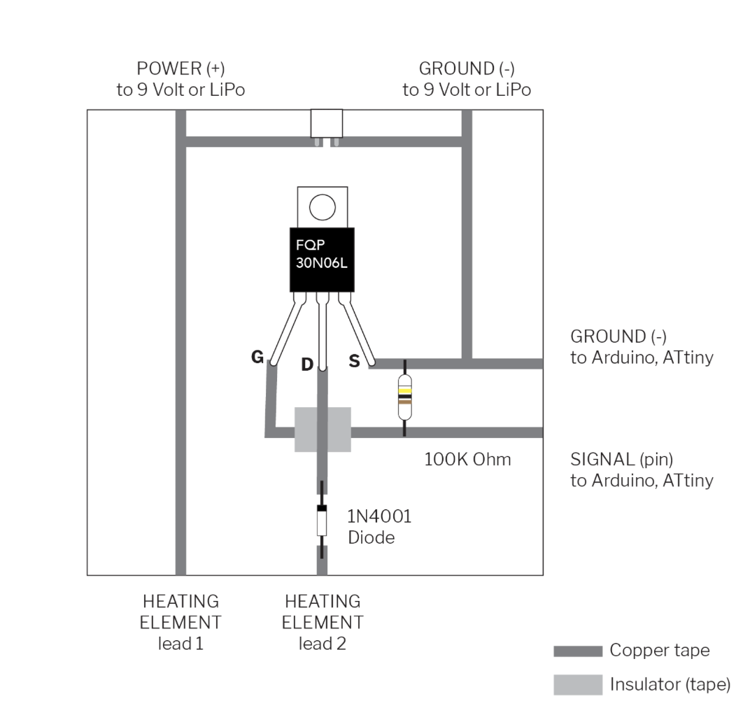
Transistor
A transistor is a miniature semiconductor that regulates or controls current or voltage flow in addition amplifying and generating these electrical signals and acting as a switch/gate for them. When working as an amplifier, a transistor transforms a small input current into a bigger output current. As a switch, it can be in one of two distinct states -- on or off -- to control the flow of electronic signals through an electrical circuit or electronic device.
There are two primary types of transistors. The first is the Bipolar Junction Transistor (BJT) and the second is the Field Effect Transistor (FET). MOSFETs are a type of FET. BJTs are usually used for electrical currents of under one amp, while MOSFETs are typically used for higher-current applications.
Mosfet
In this case, I used a Mosfet connected to the heating pad and the thermistor. A Mosfet is a metal–oxide–semiconductor field-effect transistor. It is an electronic device used to switch or amplify voltages in circuits. It is a voltage controlled device and is constructed by three terminals. Their primary use is to control conductivity, or how much electricity can flow, between its source and drain terminals based on the amount of voltage applied to its gate terminal.
To maintain the heating pad at a specific temperature and regulating it there using a thermistor is a difficult code. I used a PID control system. "A PID controller seeks to keep some input variable close to a desired setpoint by adjusting an output. The way in which is does this can be 'tuned' by adjusting three parameters (Proportional,Integral,Derivative)."Arduino, Brett Beauregard
#define heat A1           // Heat Pad
// Temperature reading variables
float R1 = 10000;
float logR2, R2, T, Tc, Tf;
float c1 = 1.009249522e-03, c2 = 2.378405444e-04, c3 = 2.019202697e-07;


// PID Constants
float Kp = 10;   // Proportional gain
float Ki = 0.1;  // Integral gain
float Kd = 1;    // Derivative gain
float previousError = 0;
float integral = 0;


// Global variables for filtering
const int numReadings = 10;
static int readings[numReadings];
static int index = 0;
static int total = 0;


void setup() {
 Serial.begin(9600);
}


void loop() {
 Vo = analogRead(ThermistorPin);
 R2 = R1 * (1023.0 / (float)Vo - 1.0);
 logR2 = log(R2);
 T = 1.0 / (c1 + c2 * logR2 + c3 * logR2 * logR2 * logR2);
 Tc = T - 273.15;
 Tf = (Tc * 9.0) / 5.0 + 32.0;


 // PID Control
 float error = setpoint - Tc;
 integral += error;


 // Anti-windup - limit the integral term to a certain range
 const float integralWindupLimit = 100.0;
 integral = constrain(integral, -integralWindupLimit, integralWindupLimit);


 float derivative = error - previousError;


 // Calculate PID Output
 float output = Kp * error + Ki * integral + Kd * derivative;


 // Safety check - limit the output to prevent excessive heating
 const int maxOutput = 255;
 output = constrain(output, 0, maxOutput);


 analogWrite(heat, static_cast<int>(output));


 //display the serial.print with 5 second intervals without delay
 static unsigned long previousMillis = 0;
 const unsigned long interval = 5000;
 unsigned long currentMillis = millis();
 if (currentMillis - previousMillis >= interval) {
   // Save the current time
   previousMillis = currentMillis;
   Serial.print("Temperature: ");
   Serial.print(Tf);
   Serial.print(" F; ");
   Serial.print(Tc);
   Serial.println(" C");
   //Serial.print("PID Output: ");
   //Serial.println(output);
 }


 previousError = error;
}
Final Photobioreactor Wearable
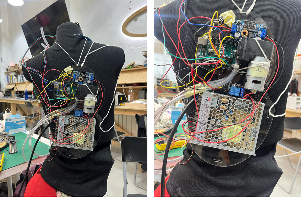
In this project, the 'wearable' part is the components attached to the back acrylic piece worn as a backpack and not embedded in the silicone.