12. Skin Electronics
Inspiration & Research
Looking through past projects from Fabricademy and searching for skin electronics in general, I found these eight projects/papers that resonated with me for different reasons.

- Cyborg Nails by Olivia Cueva
- Flexinol Dancers Glove by Emma Picanyol
- DuoSkin Temporary Tattoos by MIT's Media Lab
- Mask by Linette Manuel
-
Temporary Tattoo Sensor by University of Tokyo's Graduate School of Engineering "Designed to be hypoallergenic, the sensor can be worn for longer than similar stick-ons – such as MIT's gold-leaf temporary tattoos that can control electronics remotely.This is because of the nanoscale mesh the electrode is made from, which includes a water-soluble polymer, polyvinyl alcohol (PVA) and a gold layer – chosen because it's known to be biologically compatible. The patches are placed on the skin and sprayed with water, dissolving the PVA and allowing the wearable's gold threads to seamlessly attach to the contours, pores and ridges of human skin. Because it's breathable, it avoids the skin irritation created by other wearables with a non-dissolvable layer."
-
Thin Skin by University of Tokyo "A protective layer of organic material that's ultrathin and ultraflexible. Created high-quality protective film that’s under two micrometers thin using alternating layers of Silicon Oxynitrite and Parylene. The film kept oxygen and water vapor from passing through and could be attached to indium tin oxide (ITO) electrodes, which are used in flat-panel displays and smart windows."
- Hybrid 3D Printing of Soft Electronics Developed by creating a new technique of printing called Hybrid Printing that allows for printing of pure TPU and Silver TPU layer by layer. "The silver flakes align themselves along the printing direction so that they overlap each other like plates, improving their ability to conduct electricity along the 3D printed electrodes." The componenets are attached by placing a dot of TPU before placing the component. "Once they dries, the TPU dots anchored the components and helped to distribute stress throughout the entire matrix, allowing the devices to be stretched up to 30% while still maintaining their function."
Bare Conductive
While reading up on conductive paint I found Bare Conductive, which is also the ink we had available at FabLab Barcelona. Bare Conductive started as a project by four graduate students at the Royal College of Art who formulated the ink to be applied on skin, carry a current, and then washed away. One of their first projects was a Humanthesizer where they had dancers dancing on painted EVA foam pads. When the dancer steps on two pads, she closes the circuit and the pads make a sound.
The resistance of the ink changes with movement, as it is being stretched which could also have multiple interesting applications. It becomes a sensor.
Since the research, Bare Conductive has developed and now works on producing the inks and also kits that combine their tools with projects to educate about electronics. Electric Paint is a black water-based, non-toxic paint that conducts electricity when dried up.
Some interesting projects made with Bare Conductive:
- Liquid Lightbulb Switch: place a blob of the conductive ink inside oil, a liquid that it does not mix with, in a hollow base. Then place the lightbulb on top of that base with the electrodes in the oil. You can turn on or off the light by tilting the base until the electrodes are touching the conductive ink.
- Lamp: Using the electric paint and the light up board on paper cutouts.
- Proximity Lamp: Using the electric paint and the light up board to create a proximity sensor and switch. The light increases when your hand is closer to the sensor.
- Noise Maker: how to use a 555 timer and an Electric Paint potentiometer to make an interactive noise-maker
... and many more projects.
However, all of their advanced projects are using their own Touch Board, Light Up Board, along with the Electric Paint.
They also have a tutorial on how to make your own electric paint. You will need acrylic paint and graphite powder!
Henna
 With this information I wanted to utilize Henna as an aesthetic outcome for my project. Henna is widely used in the Middle Easte and South Asia. It was originally used in Egypt but then adopted by the rest of of the Middle East and North Africa along with India and Pakistan. Henna comes from crushed leaves of a small shrubbery that thrives in hot climates. The leaves are ground into a fine paste and turn from green to orange to the deep brown color we see. It was used in many applications from cooling off and protection from the heat to traditions around marriage, which are still in use today.
Skin Sensor
We started this week with a tutorial with Citlali where we made skin presure sensors and skin matrices. We also learnt about array function!
We started by making the skin pressure sensors with eontex and velostat.
Materials Used:
- Skin-safe double sided tape
- Conductive thread
- Velostat/eontex
- Kapton insulating tape
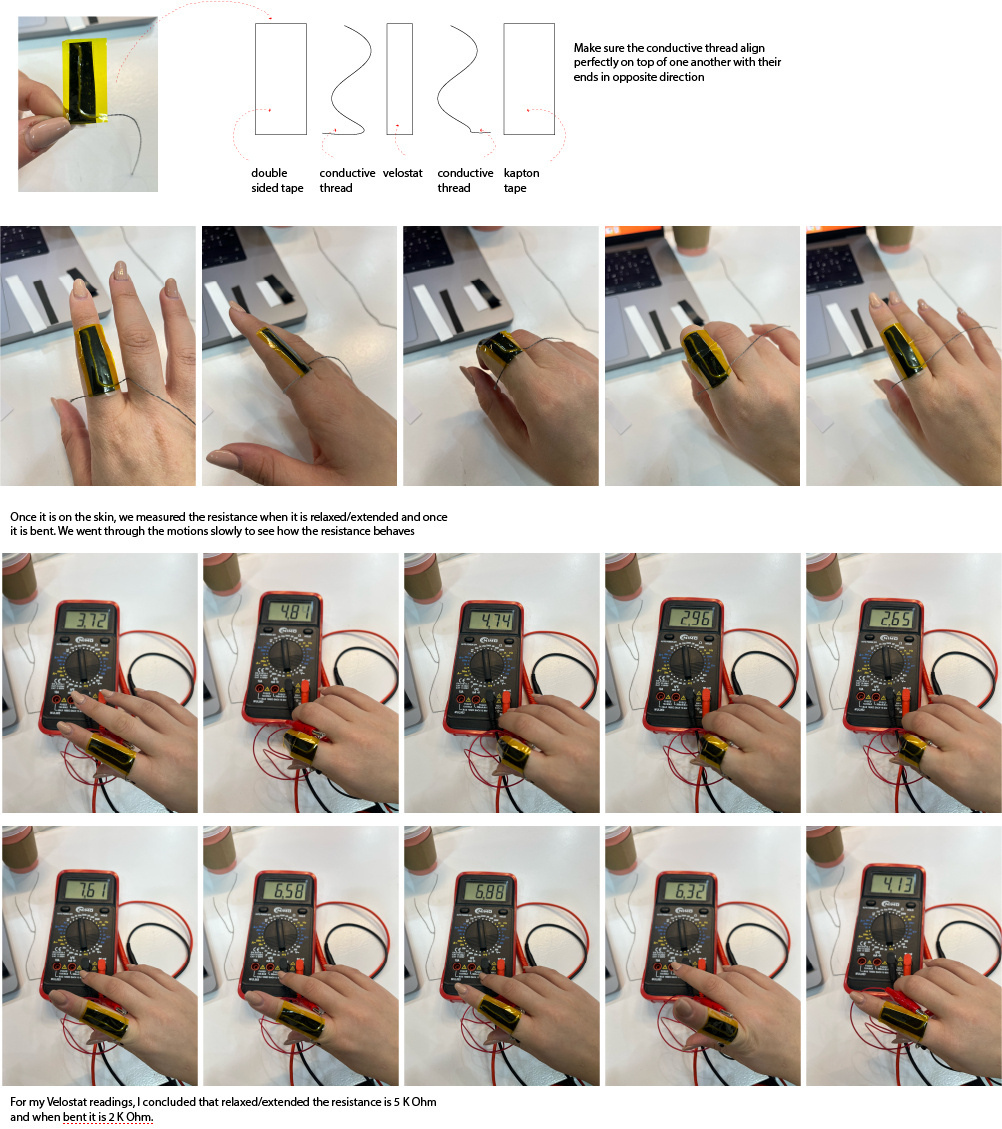
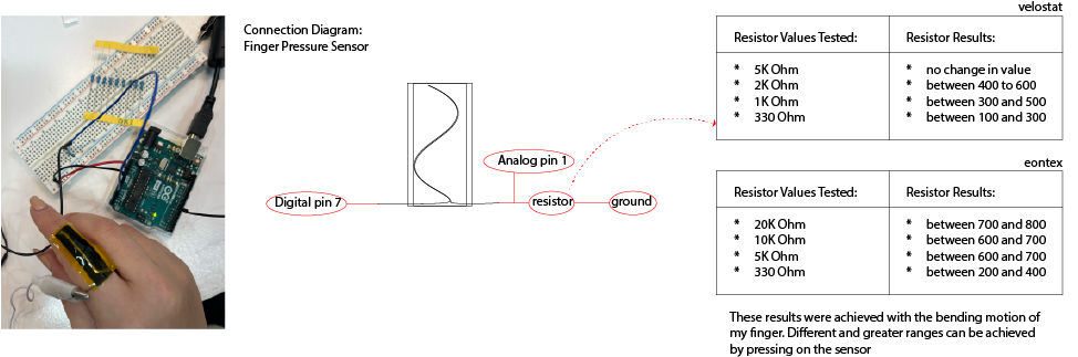
Once we know the resistance, we can connect it to the arduino using one of the resistance values as the resistor. We do this to read the values that it gives us on the monitor and then test the different resistors to give us the largest reading ranges.
All the steps above made on velostat were also made with the eontex.
Code to read the change in values when bending the finger
int sensorPin = A1;
int sensorValue = 0;
int pinD = 7;

void setup() {
  pinMode(pinD, OUTPUT);
  Serial.begin(9600);
}

void loop() {
  sensorValue = analogRead(sensorPin);
  Serial.println(sensorValue);
  delay(500);
}
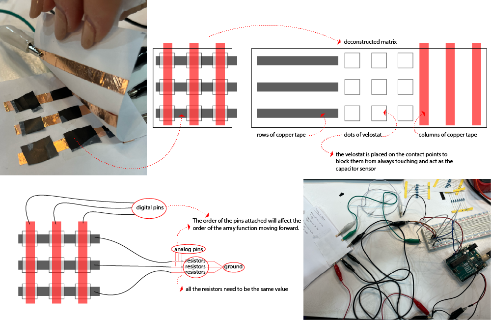
Matrix
Once we understoof how the pressure sensor worked, Citlali walked us through creating a 3x3 matrix with 9 sensor reading points. We started by creating the matrix on paper.
Code to read the matrix values as an array from 0-8 (with explanations)
#define numRows 3
#define numCols 3
#define sensorPoints numRows* numCols

int rows[] = { A0, A1, A2 };
int cols[] = { 8, 9, 10 };
int incomingValues[sensorPoints] = {};  // this is the array of all the 9 sensors

void setup() {
  for (int i = 0; i < numRows; i++) { pinMode(rows[i], INPUT); }   // so that it can be an input but increasing up to the number of rows that we have in the array
  for (int i = 0; i < numCols; i++) { pinMode(cols[i], OUTPUT); }  // so that it can be an input but increasing up to the number of columns that we have in the array
  Serial.begin(9600);
}

void loop() {
  for (int colCount = 0; colCount < numCols; colCount++) {
    digitalWrite(cols[colCount], HIGH);
    for (int rowCount = 0; rowCount < numRows; rowCount++) {
      incomingValues[colCount * numRows + rowCount] = analogRead(rows[rowCount]);  // it does this function first three times before closing and going to the one outside of it
    }
    digitalWrite(cols[colCount], LOW);  // its reading the one row three times then it turns it off and jumps to the next row
  }
  for (int i = 0; i < sensorPoints; i++) {
    Serial.print(incomingValues[i]);
    if (i < sensorPoints - 1)
      Serial.print("\t");
  }
  Serial.println();
  delay(100);
}
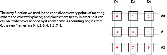
Once we have this set and able to read each square as shown above. We took it to Processing to visualize the array and matrix better.
Java Code for Processing
/*
Code based on Tom Igoe’s Serial Graphing Sketch
 >> http://wiki.processing.org/w/Tom_Igoe_Interview
 Reads X analog inputs and visualizes them by drawing a grid
 using grayscale shading of each square to represent sensor value.
 >> http://howtogetwhatyouwant.at/
 */

import processing.serial.*;

Serial myPort; // The serial port
int rows = 3;
int cols = 3;
int maxNumberOfSensors = rows*cols;
float[] sensorValue = new float[maxNumberOfSensors]; // global variable for storing mapped sensor values
float[] previousValue = new float[maxNumberOfSensors]; // array of previous values
int rectSize = 0;
int rectY;
void setup () {
  size(600, 600); // set up the window to whatever size you want
  rectSize = width/rows;

  println(Serial.list()); // List all the available serial ports
  String portName = Serial.list()[2]; // set the number of your serial port!
  myPort = new Serial(this, portName, 9600);
  myPort.clear();
  myPort.bufferUntil('\n'); // don’t generate a serialEvent() until you get a newline (\n) byte
  background(255); // set inital background
  smooth(); // turn on antialiasing
  rectMode(CORNER);
}

void draw () {
  for (int i = 0; i < maxNumberOfSensors; i++) {
    fill(sensorValue[i]);
    rect(rectSize * (i%rows), rectY, rectSize, rectSize); //top left
    if ((i+1) % rows == 0) rectY += rectSize;
  }
  rectY=0;
}

void serialEvent(Serial myPort) {
  String inString = myPort.readStringUntil('\n'); // get the ASCII string
  println("test");
  if (inString != null) { // if it’s not empty
    inString = trim(inString); // trim off any whitespace
    int incomingValues[] = int(split(inString, "\t")); // convert to an array of ints

    if (incomingValues.length <= maxNumberOfSensors && incomingValues.length > 0) {
      for (int i = 0; i < incomingValues.length; i++) {
        println("Raw sensor value: " + incomingValues[i]);
        sensorValue[i] = map(incomingValues[i], -50, 1000, 0, 255);
        println("Mapped sensor value: " + sensorValue[i]);
      }
    }
  }
}
When you are working in Processing, make sure that the Serial Monitor on Arduino IDE is closed before playing on Processing. Also, make sure to check which port/com you are using and change the value in the code as necessary.
I then translated that into lighting up LEDs depending on the specific point of the matrix and the pressure.
#define numRows 3
#define numCols 3
#define sensorPoints numRows* numCols

int led0 = 3;
int led1 = 5;
int led2 = 6;
int led3 = 10;
int led4 = 11;
int rows[] = { A0, A1, A2 };
int cols[] = { 8, 9, 10 };
int incomingValues[sensorPoints] = {};  // this is the array of all the 9 sensors

void setup() {
  for (int i = 0; i < numRows; i++) { pinMode(rows[i], INPUT); }   // so that it can be an input but increasing up to the number of rows that we have in the array
  for (int i = 0; i < numCols; i++) { pinMode(cols[i], OUTPUT); }  // so that it can be an input but increasing up to the number of columns that we have in the array
  Serial.begin(9600);
  pinMode(led0, OUTPUT);
  pinMode(led4, OUTPUT);
}

void loop() {
  for (int colCount = 0; colCount < numCols; colCount++) {
    digitalWrite(cols[colCount], HIGH);
    for (int rowCount = 0; rowCount < numRows; rowCount++) {
      incomingValues[colCount * numRows + rowCount] = analogRead(rows[rowCount]);  // it does this function first three times before closing and going to the one outside of it
    }
    digitalWrite(cols[colCount], LOW);  // its reading the one row three times then it turns it off and jumps to the next row
  }
  for (int i = 0; i < sensorPoints; i++) {
    Serial.print(incomingValues[i]);
    if (i < sensorPoints - 1)
      Serial.print("\t");
  }
  Serial.println();
  delay(100);

  int led0Map = map(incomingValues[0], 50, 950, 0, 255);
  analogWrite(led0, led0Map);
  int led1Map = map(incomingValues[1], 50, 950, 0, 255);
  analogWrite(led1, led1Map);
  int led2Map = map(incomingValues[2], 50, 950, 0, 255);
  analogWrite(led2, led2Map);
  int led3Map = map(incomingValues[3], 50, 950, 0, 255);
  analogWrite(led3, led3Map);
  int led4Map = map(incomingValues[4], 50, 950, 0, 255);
  analogWrite(led4, led4Map);
}
Electric Paint Trials
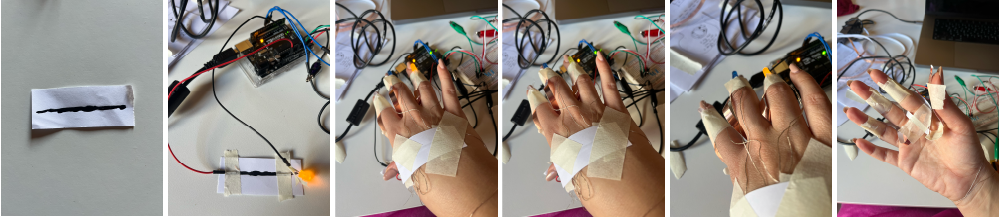
Before deciding on what my project for this week will do, I wanted to get more familiar with the electric paint. I began by painting a line on a paper and waiting for it to dry to test out whether it really was conductive enough! It takes around 15 minutes to fully dry, it is not conductive fully when wet.
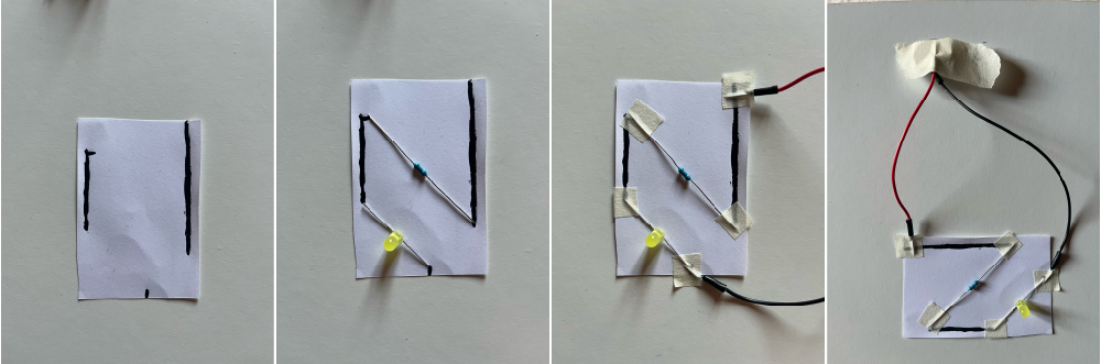
Straight Line
I first tested whether it would turn an LED on just by plugging in the ground and voltage, which it did. I then placed LEDs on my fingers and connected the grounds to my palm and thumb while the voltages to the paper. As it was such a makeshift circuit with tape and thread and was connected to a 3V coin battery, it was only able to turn on one of the LEDs.
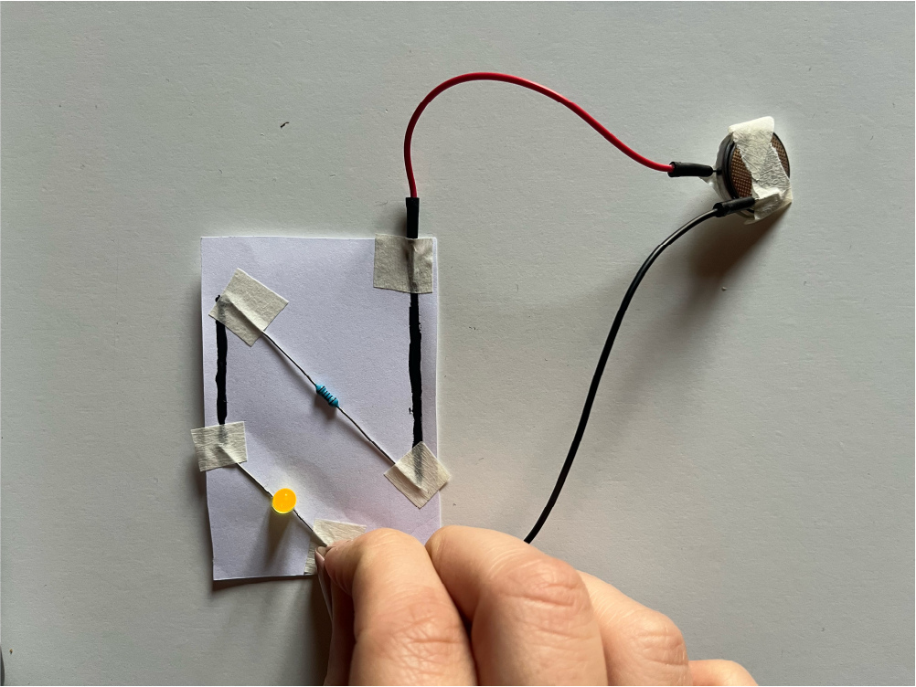
Z-circuit
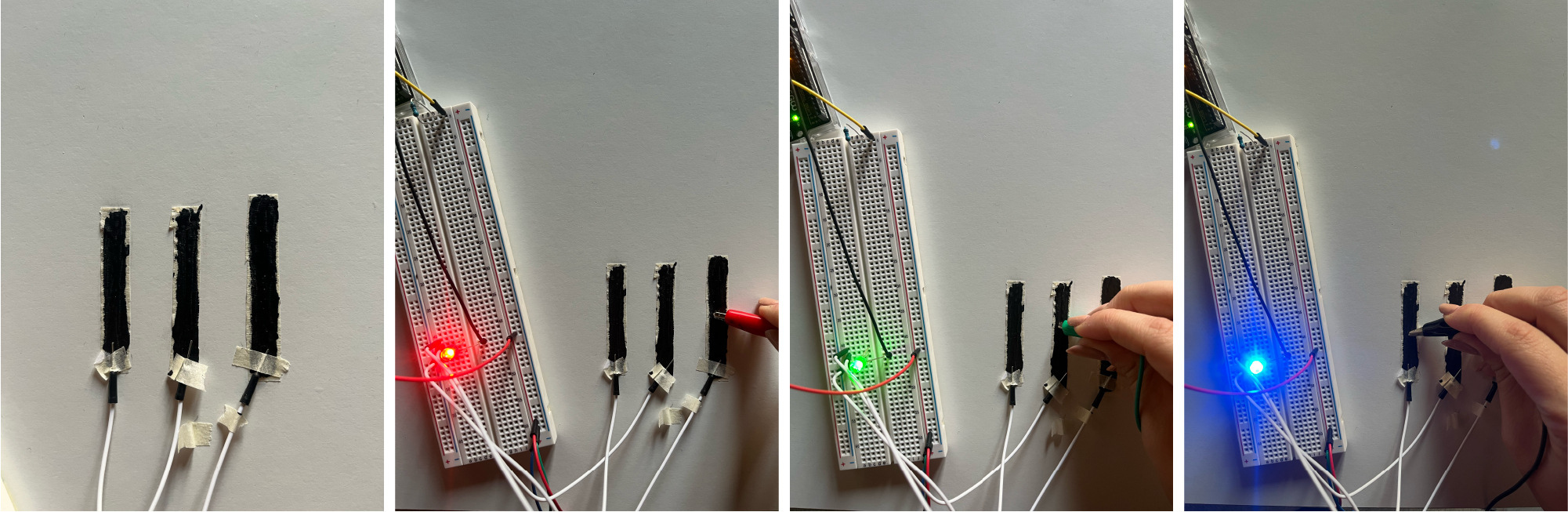
I then drew out a new circuit that has a resistor, LED, and a battery. This circuit did not light up the LED. I believe that there wasn't enough ink on the paper making it less conductive and with the addition of the resistor it is too resistive. The layer of ink needs to be thicker to conduct better.
To check that theory, I used the multimeter to measure the resistance in each line from the two above.
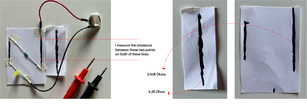
As seen above, the straight line has less resistance allowing more current to pass through it while the other one is more resistive which is why it wasn't lighting up the LED.
I then added a little more ink over the whole circuit and tested it again. It then lit up!
Masking Tape
Moving on from paper, I wanted to try it out on masking tape so I could start to tape it on my skin and see how it would work with the flexibility and movement.
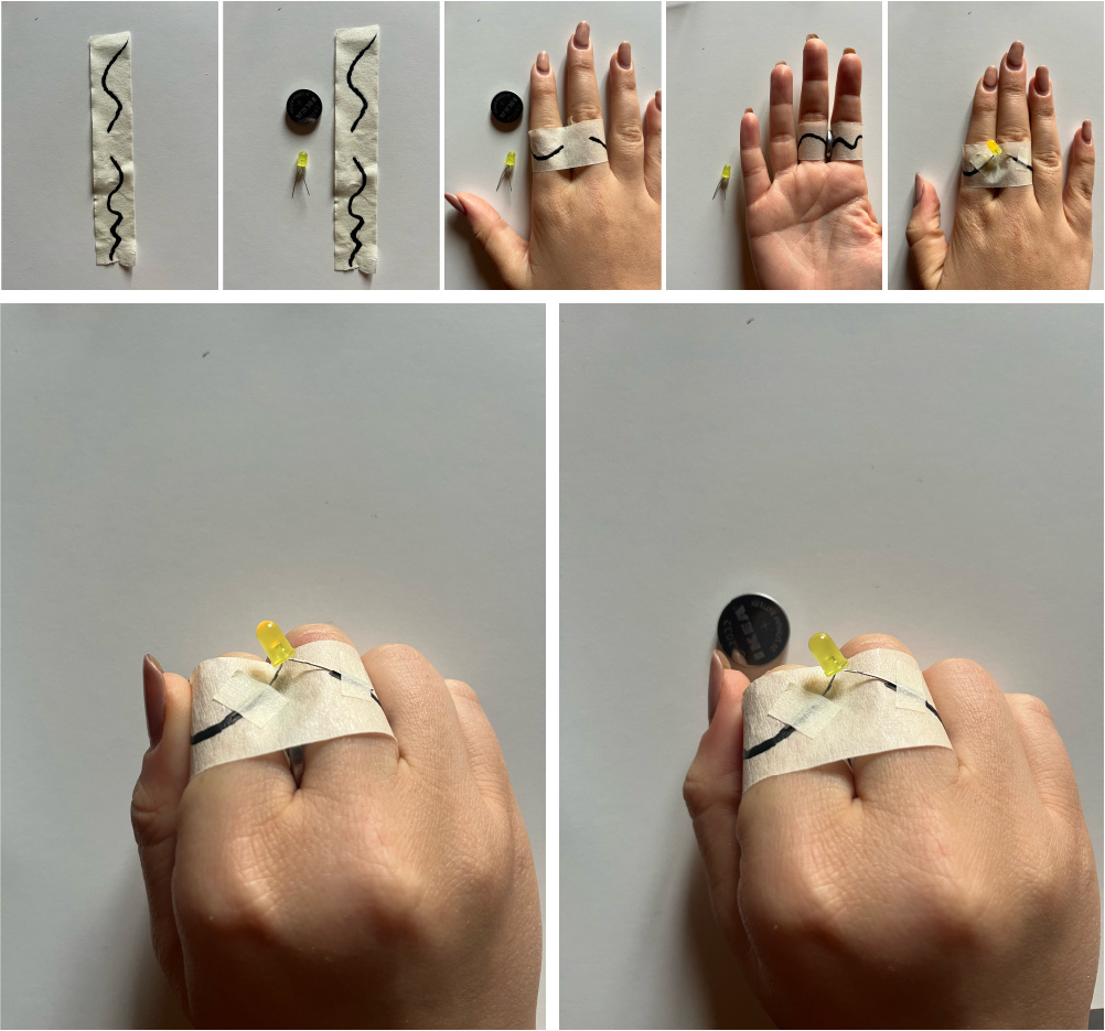
One thing that will be tricky once developing a project is the fact that the coin battery has facing sides for the voltage and ground which is why here i placed it between my fingers.
Henna Masking Tape
I placed tape around my pinky finger to my wrist and began drawing with the electric paint as if it were Henna. One of the lines from my pink to my wrist was the positive and the other was the negative.

I initially had some issues with it due to the masking tape but once I made sure all the connections are really touching, it lit up well. To explore this idea further I will need to find an alternative to the tape. As a next step, I used cling film!
Henna SMD LED
I tested out the cold solder method with the electric paint and soldered red SMD LEDs to a henna pattern I had already drawn on cling film. I soldered the positive end to the main frame and need to design a pattern for all the grounds.
I scratched the above pattern and also using the cling film and decided to paint on my hand directly!

As the skin has a lot of texture, and when it bends it stretches the paint was a little difficult. The lines would crack and break the circuit. However, I kept painting in the cracks and was able to get a cmplete circuit. But then, the Red SMD LEDs each require avoltage of 1.8V and I have 5 in series on each side meaning I need 9V for each line and 18V in general. Which would feel like a slight 'tickle'.
| Positives | Much easier to pain on, cold soldering works much better, can really feel the movement and can design for it better. |
| Negatives | Need to calculate the voltages and currents so it does not shock me. Or need to separate the volts and grounds to different power sources. |
To make this work better, I would need multiple micro batteries as seen in this project.
Electric Paint Potentiometer
As all the trials above were digital I wanted to try some analog sensors with the electric paint.
This first trial turns the line of paint into a potentiometer by dragging the A0 jumper wire across the line. When it is closer to the 5V wire, the number goes up even reaching 1023 at times. When it goes towards the GND wire, it goes down to around 200.

I plugged in an LED and tested out the dimming. At first, using just the jumper wire to go back and forth I wasn't receiving the best values. So I re-purposed the tape from earlier and attached it to my finger and used it as the slider to which I received much better results.
To begin integrating it as a skin electronic, I first painted a larger wavy line on masking tape along that is to be taped to the arm and stroked to increase and decrease the LED brightness.

Electric Paint RGB LED Color Slider
The RGB LED slider is three different strips of electric paint where each one acts as a slider for one color (R,G,B). They act as potentiometers for the RGB LED. It only requires a 9V battery, 3 separate strips, RGB LED, and jumper wires.
I began by testing it on the masking tape first to make sure the connections are all working.
In the lab we have the small SMD RGB LEDs and I wanted to try using them. I looked for their schematic online to find which pin corresponds to which color and whether it is a normal cathode or anode. I found this below as a guide but then tested it with a multimeter.
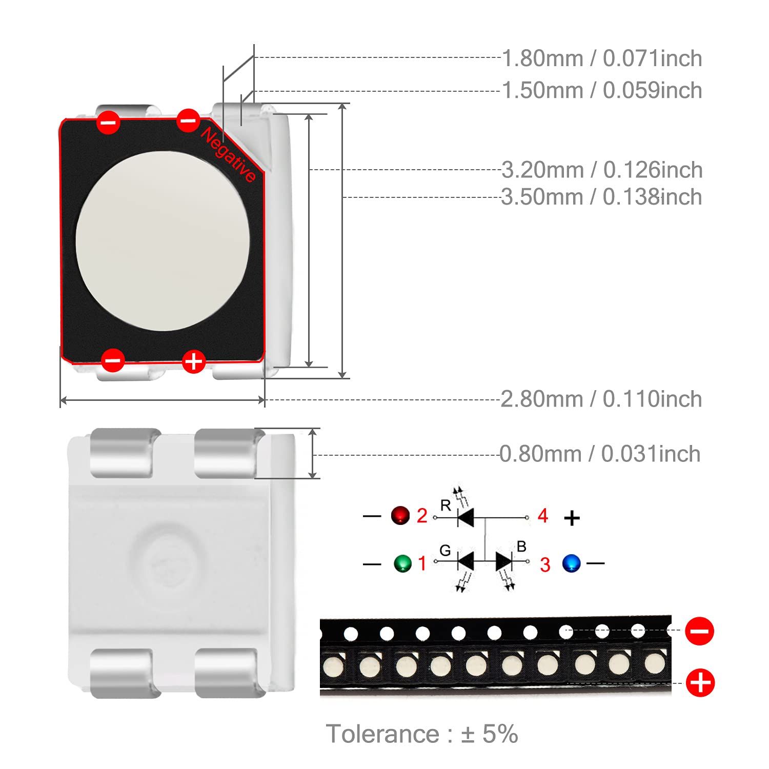
With a multimeter you can check but placing the each prong on either end until you see one of the colors light up. In my case it turned out that it is a normal anode.
Bare Conductive's Electric Paint also works as a cold solder according to their website. So I wanted to test that and attached the solder to each pin using a dot of electric paint and allowed it to dry.
I connnected this soldered SMD RGB LED to the same system and tested it out and it was working very well as both the potentiometer sliders and the LED colors. Time to make a skin electronic out of it!
The concept for this idea is to create a henna tattoo with an SMD RGB LED embedded in it and a stroke sensor on the nails of my opposite hand. When I stroke the henna and stop, the LED is to remain at that color.

code is currently working, connections are not
Electric Paint Capacitive Sensor
What is a Capacitor Sensor?
A capacitive sensor functions by detecting altering capacitance of a nearby object. When there is an applied electric field, the capacitance of the object changes. The sensor then measures this change in the capacitance and reports it back to a receiver. If the electric field is removed, then the capacitance of the object decreases. The sensor then reports that decrease to the receiver. The receivers use this information to determine the change in capacitance based on the time of the change. **They are sensitive and easily affected by other elements like temperature and humidity.
To create a capactive sensor with the electric paint, the tutorial uses two digital pins (4 and 2) with a 1M Ohm resistor between them. Pin 2 is directly connected to the sensor (electric paint). Once you come closer to the electric paint, the values shoot up and when you are further away they are smaller. Similar to a proximity sensor.
I then painted a square on tape and cut it out and placed it on cling film to wrap it around my arm and see how the ranges changed. Because it is touching the skin, maybe from the heat of the skin, the values are already quite high and the LED is always on.
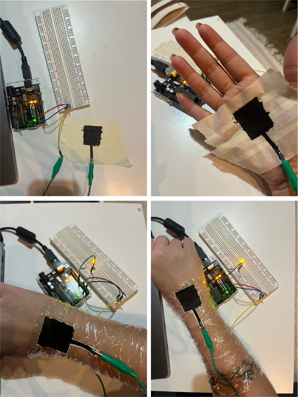
 I then added the long wavy line to connect the pin to the square and wrapped the cling film around my arm more securely. I noticed that with this sensor I'm able to see changes in the value while approaching the ink, with added pressure, and with movement.
Values:
- Proximity: if my arm is laying flat on a surface the values are around 30 and then with approaching it with my other hand they go up to 200s.
- Pressure: with my arm laying flat on a suface the values are around 30 and when pressing with my other hand on top of the square and some of the line the values jump up to 700.
- Movement: as I move my hand and fingers and rotate my wrist, the cling film and ink touches my skin at different points and when it does the values vary from 0 to 200.
Taking it one step at a time, I now tried moving the LED onto my hand as well and finding ways to connect it to the arduino. I made the LED and resistor into a ring and used the solder to wrap it around the connections to hold them together and to the jumper wires. Next step is to figure out how to extend the connections and attach the microcontroller to my arm as well.
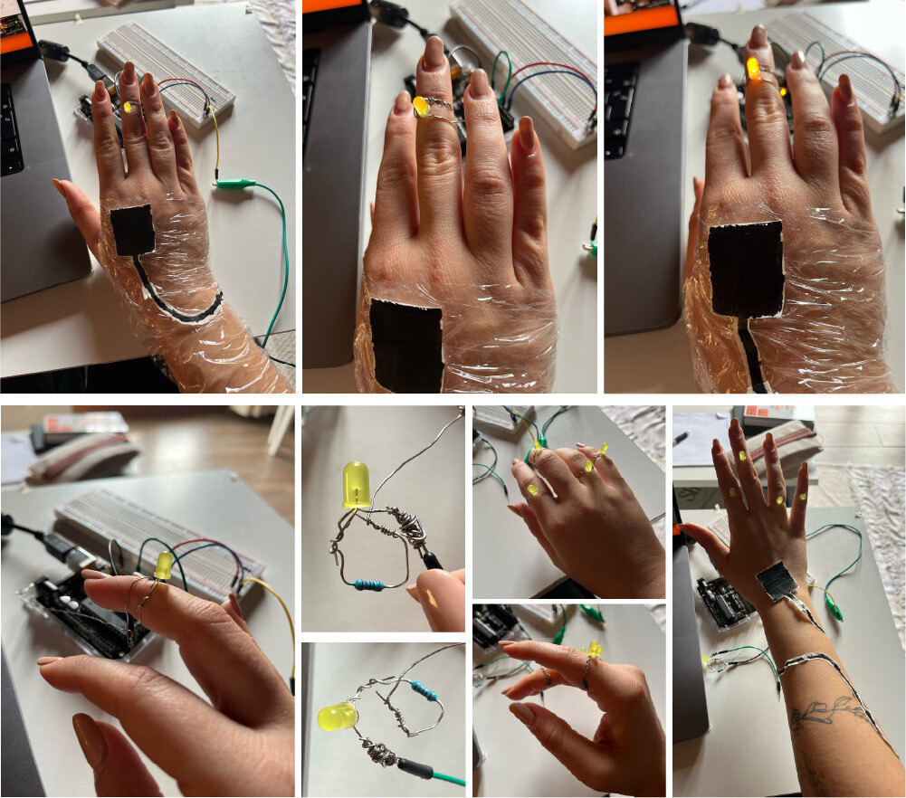
I began attaching the rings to the rest of the circuit. I attached the solder from the front to the pin jumper wire. The ground was attached from the palms using the electric paint and wrapped around the arm following the paths.

Connections

Code for the Capacitor Sensor to turn on LED after a specific threshold.
#include <CapacitiveSensor.h>
int ledPin = 9;
const int threshold = 10000;
CapacitiveSensor sensor = CapacitiveSensor(4, 2);  // 1M resistor between pins 4 & 2, pin 2 is sensor pin

void setup() {
  Serial.begin(115200);
}

void loop() {
  long measurement = sensor.capacitiveSensor(30);
  Serial.println(measurement);
  delay(100);
  if (measurement > threshold) {
    ledPin = map(measurement, 0, 1023, 0, 255);
    analogWrite(9, ledPin);
  } else {
    analogWrite(9, 0);
  }
}
When transforming these tutorials above onto the skin, the values automatically change and the code would need to be readjusted for that.