Wearables
Students checklist week09
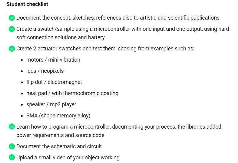
Image Source: Fabricademy Handbook
1. Objective
We started the week with another great and inspiring lecture by Liza Stark, who introduced us to the key terms, concepts, and vocabulary within the field of wearables.
The assignment for this week is to create 3 swatches in total, focusing on outputs designed to be worn on the body: * Two actuator or output swatches designed for the body, tested with a microcontroller board of our choice. * One interactive swatch combining one input and one output of our choice, intentionally designed to be worn on the body.
When designing for the body, there are several important factors to consider—such as defining the problem, identifying who we are designing for, managing time and project scope, and evaluating our ideas against specific design values and constraints.
Because many wearable actuators (like heating elements or speakers) require more current than a microcontroller pin can provide directly, we need to build circuits using transistors (such as an N-Channel MOSFET) to control a secondary power source. As a first step in this process, we will prototype these transistor circuits on paper or cardboard—and that is where I am starting my week.
2. References, research & inspiration
References from bootcamp2026
As a foundation for this week's work, I am drawing on my hands-on experience from the Fabricademy Bootcamp in Ireland (May 2026) at Creative Spark Fab Lab in Dundalk. During Day 3 of the program, I participated in an E-textiles & Wearables lecture and workshop led by Jessica Stanley, where we explored conductive and resistive materials, soft sensors, and built soft circuits using the FabriXiao (Seeed Studio XIAO ESP32C3) and LEDs.
You can find the presentation, circuit documentation, and Arduino code from the session in the Fabricademy Bootcamp Ireland 2026 Handbook (Day 03).
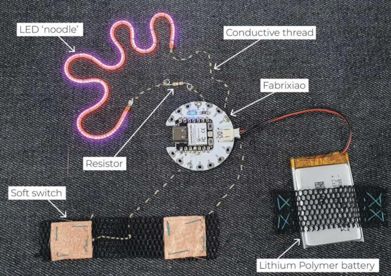
Image Source: FabriXiao Soft Circuit, picture from Fabricademy, link from handbook
To make the microcontroller modular and reusable across different swatches, the XIAO board is mounted using sewn-on snap buttons (press studs). This makes it quick and easy to attach and detach it from the circuits.
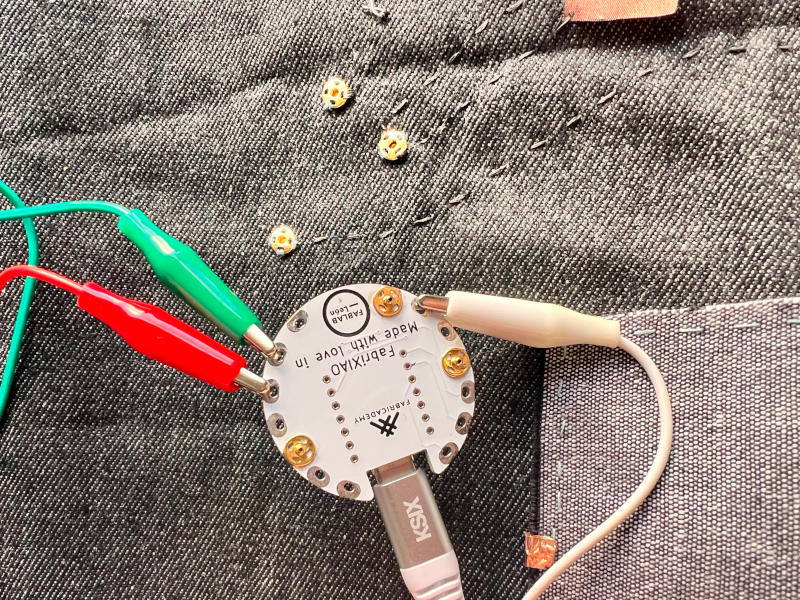
Image Source: Sewable Xiao connected using sewn-on snap buttons, Tina Grønbech
get inspired!
Check out and research alumni pages to betetr understand how to document and get inspired
-
Thermochromic screenprint - Ruby Lennox - FabLab Bcn
-
Led responsive glove - Marion Guillaud - Le TextileLab lyon
-
Thermochromic and sound research - Stephanie Johnson - TextileLab Amsterdam
-
Interactive glove - Stephanie Vilayphiou- Green Fabric
Add your fav alumni's pages as references

"Lorem ipsum dolor sit amet, consectetur adipiscing elit, sed do eiusmod tempor incididunt ut labore et dolore magna aliqua. Ut enim ad minim veniam, quis nostrud exercitation ullamco laboris nisi ut aliquip ex ea commodo consequat. Duis aute irure dolor in reprehenderit in voluptate velit esse cillum dolore eu fugiat nulla pariatur. Excepteur sint occaecat cupidatat non proident, sunt in culpa qui officia deserunt mollit anim id est laborum. Lorem ipsum dolor sit amet, consectetur adipiscing elit, sed do eiusmod tempor incididunt ut labore et dolore magna aliqua.
Caption for the left image
Caption for the right image
-
Download references Links to online reference files, PDF, booklets
-
or embed your own PDF as:
- Video references: Vimeo (only when not yours)
- Video references: Youtube (only when not yours)
3. Tools
4. Process and workflow
Hands-on Tutorial with Jessica Stanley
In this session, we created a simple output circuit using a sewable NeoPixel (an LED designed to be stitched directly onto textiles).
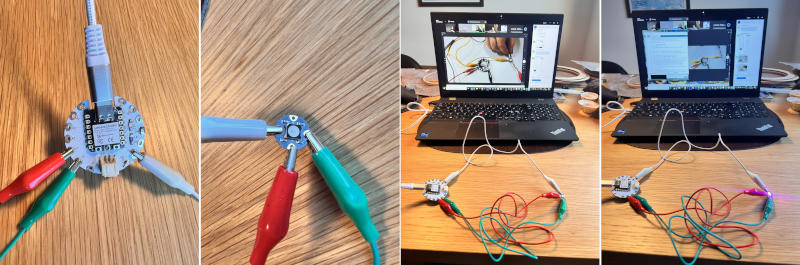
Image Source: Hands-on tutorial output, Tina Grønbech
Hardware and Connections
We built the circuit around the microcontroller board we currently have available. I used the same i used in the E-textile week a Seeed Studio XIAO ESP32C3 board and connected it to the NeoPixel module as follows:
| XIAO ESP32C3 | Sewable NeoPixel |
|---|---|
| GND | - (Minus) |
| 5V | + (Plus) |
| D4 | → (Arrow In / Data In) |
Code Setup in Arduino IDE
To make the LED light up, we used a standard example from Adafruit as a starting point. Here is how to find the code in Arduino IDE, once you have connected your XIAO in the Arduino IDE:
- Go to File > Examples.
- Scroll all the way down to Adafruit NeoPixel.
- Select simple.
This opens a basic code structure that you can easily modify afterward—for example, changing the pin number (to D4 in this case) and customizing the colors and brightness of your NeoPixel. During the exercise, we customized the NeoPixel's colors, brightness, and color transitions by adjusting lines 42 to 50 in the sketch below.
Arduino Code simple output:
// NeoPixel Ring simple sketch (c) 2013 Shae Erisson
// Released under the GPLv3 license to match the rest of the
// Adafruit NeoPixel library

#include <Adafruit_NeoPixel.h>
#ifdef __AVR__
 #include <avr/power.h> // Required for 16 MHz Adafruit Trinket
#endif

// Which pin on the Arduino is connected to the NeoPixels?
#define PIN        D4 // On Trinket or Gemma, suggest changing this to 1

// How many NeoPixels are attached to the Arduino?
#define NUMPIXELS 1 // Popular NeoPixel ring size

// When setting up the NeoPixel library, we tell it how many pixels,
// and which pin to use to send signals. Note that for older NeoPixel
// strips you might need to change the third parameter -- see the
// strandtest example for more information on possible values.
Adafruit_NeoPixel pixels(NUMPIXELS, PIN, NEO_GRB + NEO_KHZ800);

#define DELAYVAL 500 // Time (in milliseconds) to pause between pixels

void setup() {
  // These lines are specifically to support the Adafruit Trinket 5V 16 MHz.
  // Any other board, you can remove this part (but no harm leaving it):
#if defined(__AVR_ATtiny85__) && (F_CPU == 16000000)
  clock_prescale_set(clock_div_1);
#endif
  // END of Trinket-specific code.

  pixels.begin(); // INITIALIZE NeoPixel strip object (REQUIRED)
}

void loop() {
  pixels.clear(); // Set all pixel colors to 'off'

  // The first NeoPixel in a strand is #0, second is 1, all the way up
  // to the count of pixels minus one.
  for(int i=0; i<NUMPIXELS; i++) { // For each pixel...

    // Smooth color fade from blue to red
    for(int j = 0; j<255; j++){
      pixels.setPixelColor(i, pixels.Color(j, 0, 255-j));
      pixels.show();   // Send the updated pixel colors to the hardware.
      delay(20);       // Slow down the color change
    }
  }
}
Prototyping the Transistor Circuit
To control higher-current wearable actuators (such as heating elements, coils, or soft speakers) that require more power than a microcontroller pin can safely provide directly, I built a transistor circuit prototype on cardboard using copper tape.
Components Used
- Microcontroller: Seeed Studio XIAO ESP32C3
- MOSFET: IRLB8721 (N-Channel logic-level MOSFET)
- Diode: 1N4001
- Resistor: 10 kΩ (pull-down resistor between Gate and GND)
- Materials: Cardboard, conductive copper tape, and insulating tape (for the overlapping trace bridge)
Building & Soldering on Cardboard
Following the tutorial schematic from our instructors, I laid out the copper tape tracks on a piece of cardboard. To make it easy to connect alligator clips later, I folded the ends of the copper tape over the edges to the back of the cardboard.
Before soldering the components, I placed a piece of insulating tape where the Gate (G) trace crosses over the Drain (D) trace to prevent a short circuit. Since the adhesive on the back of copper tape is not reliably conductive, I also added small solder joints at all overlapping corners of the tape to ensure a solid electrical connection.
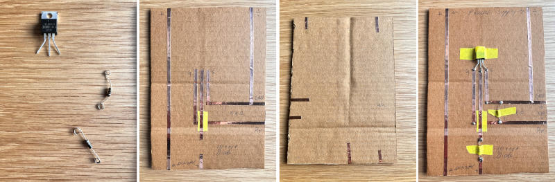
Image Source: Transistor circuit on cardboard, Tina Grønbech
For the component placement:
* IRLB8721 MOSFET: Placed with the printed front facing up (G on the left, D in the middle, S on the right).
* 10 kΩ Resistor: Soldered across the PIN and GND traces to act as a pull-down resistor, ensuring the MOSFET turns off cleanly when no signal is sent.
* 1N4001 Diode: Soldered into the gap on the middle trace (D) leading to the actuator, with the silver stripe (cathode) facing up toward the MOSFET.
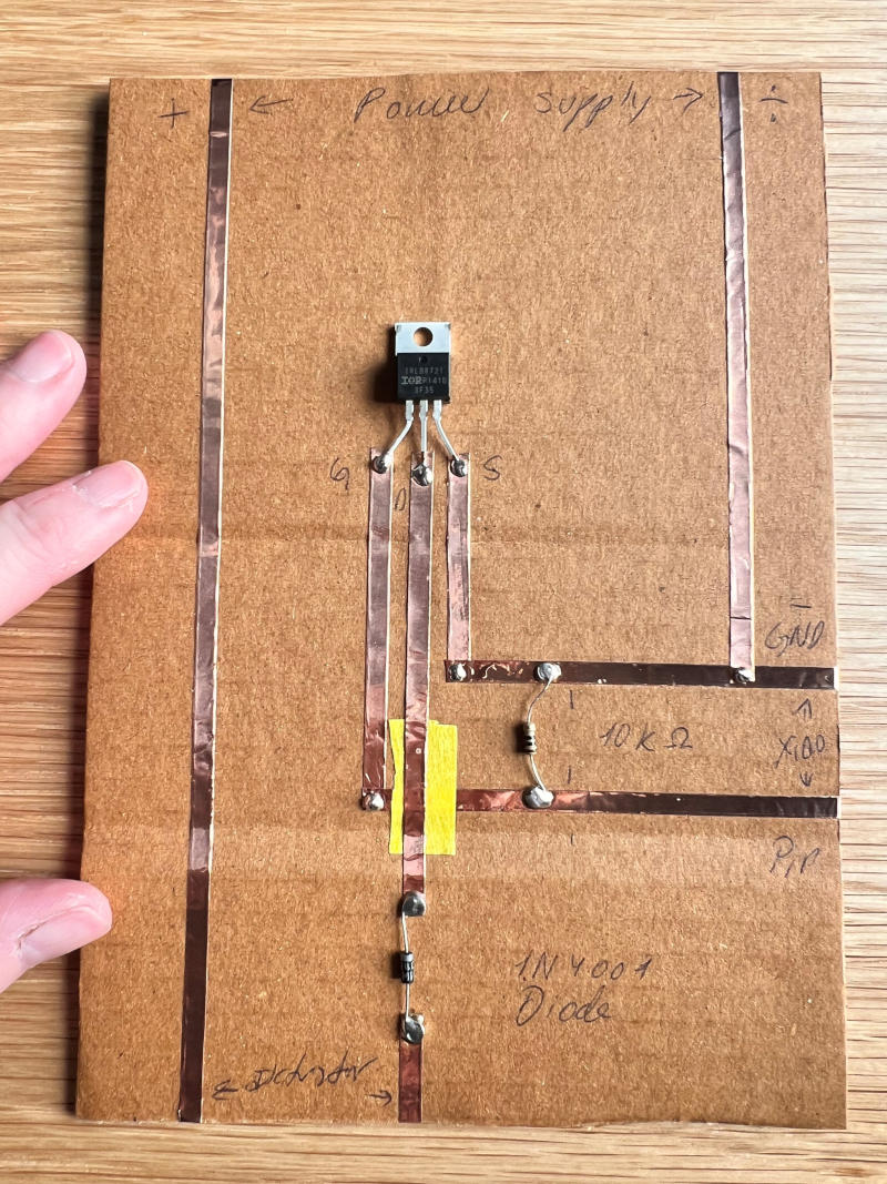
Image Source: Transistor circuit, before testing if it works, Tina Grønbech
Note on Diode Placement (Flyback Protection)
I built my prototype strictly following our instructors' circuit template. However, while researching, I came across an interesting technical discussion in Svetlana Khachatryan's Week 09 documentation regarding feedback from instructor Emma Pareschi.
When the 1N4001 diode is placed in series between Drain (D) and Load (-), it acts as a one-way valve rather than a true flyback diode. To properly protect the MOSFET from inductive voltage spikes (especially when driving coils or motors), the diode can alternatively be placed across Load (+) and Load (-) with the cathode (silver stripe) connected to Load (+).
Design Concept: Maritime Safety Wearables
Drawing on my background as a maritime officer, as well as five years working in a ferry shipping company as an HSE Manager and Designated Person Ashore (DPA), my main focus for this week's wearables assignment is personal safety at sea and on the dock. Working in marine environments—often in darkness, fog, or rough weather—requires gear that is intuitive, durable, and easy to wear over heavy foul-weather outerwear.
To address this, I designed a series of wearable swatches centered around high-visibility signaling and localized audio alerts:
- Actuator Swatch 1 – High-Visibility NeoPixel Armband (Upcycled): An elastic reflective band worn over the sleeve of a jacket, equipped with four sewable NeoPixels. It combines passive safety (reflective strips) with active safety (programmed light signals) for low-visibility conditions.
- Actuator Swatch 2 – The Audio Safety Brooch (Soft Speaker): A spiral embroidered with conductive copper thread and paired with a magnet, designed as a detachable brooch for a jacket collar or shoulder to deliver localized audio alerts close to the wearer's ear.
- Interactive Swatch 3 – Wearable Safety Trigger (Input + Output): Combining a soft textile switch or capacitive sensor with the visual/audio output, allowing the wearer to easily trigger an alert even when wearing heavy work gloves.
Swatch 1: High-Visibility NeoPixel Armband
Ergonomic Layout & Power Integration
To ensure the armband is practical and comfortable to wear on a jacket sleeve, I refined the component placement after testing the fit on the arm:
- LED Positioning: The four sewable NeoPixels are grouped closer together toward the center of the band so they sit directly on the front/outer side of the arm for maximum visibility.
- Microcontroller Orientation: The round FabriXiao board (with the Seeed Studio XIAO ESP32C3) is positioned toward the inner arm (near the underarm) where it sits flat and protected. By orienting the board with the USB-C port facing up and the JST battery connector facing down, it is easy to plug in a cable for reprogramming without removing the board.
- Battery Pocket (3.7V LiPo): A small protective fabric pocket is sewn onto the back of the elastic band directly behind the FabriXiao to house a 3.7V 280mAh (1.036Wh) LiPo battery. This keeps the wire short, tucks the battery safely away from external snags, and utilizes the FabriXiao's built-in charging circuit.
Circuit Architecture (Parallel Power, Series Data)
When connecting addressable LEDs like NeoPixels, the circuit combines two types of connections:
* Power (5V/+ and GND/-) in Parallel: All four NeoPixels share the same continuous power and ground lines running along the inner edges of the grey reflective strips.
* Data (→) in Series: The data signal travels sequentially from the microcontroller pin (D4) into the first NeoPixel (→), out the other side, and into the next NeoPixel in the chain.
...
5. Results
Results & documentation
- Don’t forget to document the outcome including:
- Final result
- Photos from different stages
- Videos of movement or interaction, show how a material moves, something was assembled or the interaction
- Include measurements or a reference object to give a sense of scale
- Describe the (material) properties of what you made
- Comparison between attempts, if you did multiple experiments or generated multiple files before fabricating / deploying. You can use a table as shown in week 4
6. Weekly reflection & critical thinking
- What did I learn? What did I personally find interesting or surprised me?
- What would I do differently? If something "failed" do I know how else to tackle it now?"
- How does this connect to my final project or my learning trajectory?
- What are implications and possible applications, think also from the ethical or environmental aspect, how it could connect to your practice and project?
NuEval — final step
Go to NuEval and fill in the checklist, when not complete notify your instructor.
7. Fabrication files & References
-
File: 3d modelling of mannequin ↩
-
File: Laser cut sheets ↩
-
Reference: Author; Title; Source; year ↩