5. E-Textiles and Wearables I#
Another good global lecture, this week by Liza Stark, the Soft Circuiteer. I’ve listened to many lectures about electronics, but Liza’s one was the most comprehensive and comprehensible so far. We began with the basics - what is a circuit and moved through to what sort of sensors we might make, with which materials and how we can program them in the Arduino IDE. She showed many examples and created a set of excellent notes for us on the page linked above.
3D printing seams and conductive traces
electronics explained#
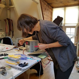
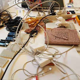
The next day, we had an intensive day locally with Emma who I think is the best electronics explainer in the world ever. She unpacked Liza’s lecture for our group, mixing explanation with hands-on experimentation. You can see below that she had prepared some super-useful presentations for us and that we also got to play with the power supply, multi-meters, arduinos (or similar) etc. Our table was quite tidy and got progressively messier during the day.
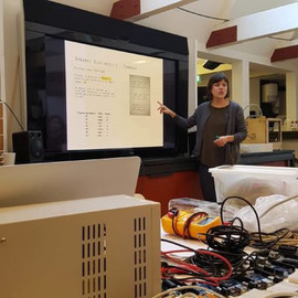
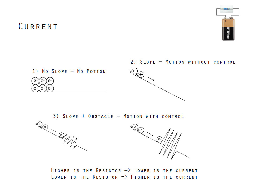
I particularly liked this visualisation Emma had in the presentation, showing the effect that resistors have in a circuit.
things for the future#
- Zipper Switch
- paper electronics with Jie Qi
- sparkfun paper electronics
- more paper electronics
- paper circuits again
- electronics tutorials sitemap
- arduino cookbock
the quandary#
As I said in the first week, I struggle to think of electronic interactions that aren’t contrived and pointless. I like to design interactions, but focus on spatial interactions, interactions with objects, communication, web-based interaction etc. My final project for Fab Academy was probably the closest I’ve come to designing an electronic component into one of my pieces. Even so, we’ve made many of the WeRu standing desks in the five years since, and never included that aspect to them… partly because I never fully resolved it…and I never resolved it because it didn’t seem necessary. Will I solve this quandary in the course of this week…? Read on and see.
testing#
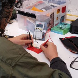
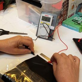
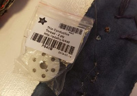
I did a bit of testing of the materials in the lab, using my awesome and cute multimeter, and decided to do my first experiment. I also, eventually, looked at the datasheet for copper taffeta but that’s something I’ll talk about later.
the tilt switch#
The experiment would be a simple switch but would test two things - I wanted to understand how to make a Dorset Button and to see whether it would work as the framework for a speaker, even though we’re doing inputs this week, not outputs. As I said in the first week, I’m quite interested in doing an interactive garment with speakers in it. Actually, Liza showed an interesting one from Kobakant during her lecture.
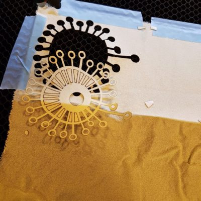
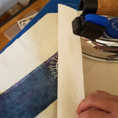
I also wanted to try out using fusing, and to use the materials that we dyed the previous week. You’ll remember that I was the keeper of the blurple (blue & purple) dye pot, so I felt like I should use those samples, but there were some other colours left in the box of leftovers that I used as well. I found some silk and ironed some fusing onto it, then lasercut a shape on it which I then ironed onto the blurple calico sample.
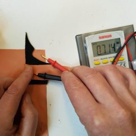
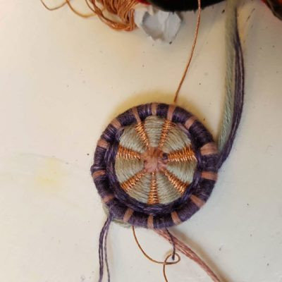
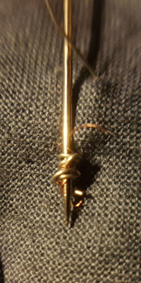
Semi-following the instructions for the Dorset Button in the link above, but also making it up as I went along. I tried to keep the copper thread in the spiral separate by putting the cotton thread in between, but of course, they crossed, leading to pretty mediocre results when tested with the multimeter. Given that Emma said an average speaker is 8ohms, and I was getting less than 1ohm, and the amps in the lab measure between 4 - 8ohms, I decided to carry on with this week’s project and use a different copper material for the next speaker experiment.
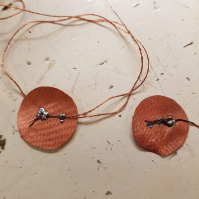
components#
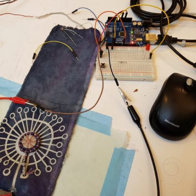
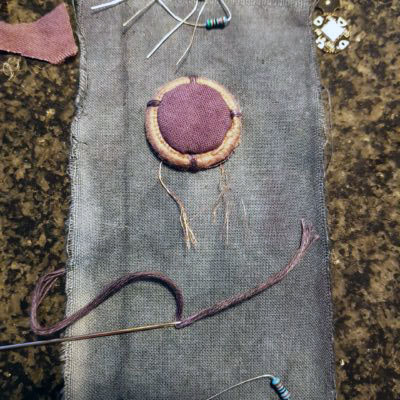
As you can see in the images above, it all came together. The components of the switch are:
- the dorset button with copper thread
- the silk dandelion overlaid with a ripstop section
And there are clearer images of these in the instagram post below.
The ripstop has a ‘leg’ for the alligator clip to connect to, and the button has a continuous length of copper running from the back of the fabric through the plaited component, spiralling in the centre of the button to the bottom edge. It’s more than is necessary, but you’ll remember I was testing something else.
the outcome#
I hope you can also see in the video below that I got it working with some hacked together code that I did during the session with Emma.
I’m not a fan of scrolling past endless lengths of embedded code on a website, so any code longer than a couple of lines will be in the download section.
//wendy's switch

int sw_pin = 8; //pin of the dccduino
int sw_value = 0;

void setup() {
  // put your setup code here, to run once:
  pinMode(sw_pin, INPUT); //define the role of the pin
  Serial.begin(9600); //communication rate
}

void loop() {
  // put your main code here, to run repeatedly:
  sw_value = digitalRead(sw_pin); // will read if the switch is connected or not
  Serial.print("my switch value is: ");
  Serial.println(sw_value); //will print in the serial monitor my switch value is and then a 0 or 1
  delay(1000); // delay of one second


}
You can scroll past endless pictures instead… :)
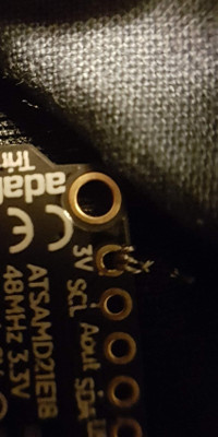
trinket M0#
Every time we do an adafruit order at Fab Lab Wgtn, it’s big enough for them to throw in some freebies. Recently we got a trinket M0 and I brought it with me so I could have a play around with it during fabricademy.
I have already a few adafruit boards set up in arduino, and their python-based software as well, but I needed to do a little more downloading and setting up for this board. I followed the instructions provided on their site (link above), including this handy tip:
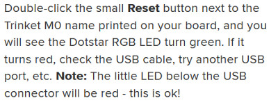
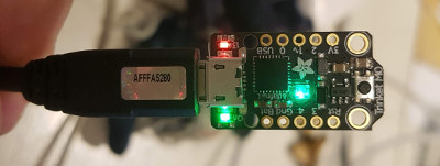
My first cable was’t working, even though I thought it should…
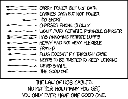
(thanks to Nicolas De Coster for the tip about XKCD hilariousness)
…so I found another one, and saw the Dotstar turn green. Yay, easy troubleshooting… however, it was after I’d checked all the other wires with the multimeter that I found this tip… sigh
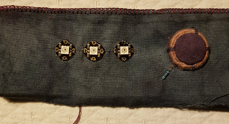
testing the trinket#
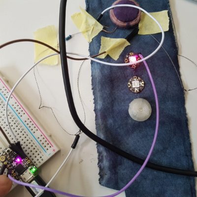
I breadboarded up a simple circuit with one sewable neopixel, but the trinket M0 isn’t as handy as other versions because the connections are pretty loose and variable on the breadboard. I’m holding everything in place and holding my breath… You can see in the video below that it worked, but when I tried to add another I couldn’t hold everything in place well enough to make it work. Anyway, I have the workflow now, and will carry on to include my tilt switch and then the pressure sensor.
If the video isn’t loading and says you have to download it, refresh the page instead…
I will sew the neopixels in place on the fabric now, though it feels like I’m committing too early. I think that’s because I’m used to making hard circuits. I can easily snip threads and re-sew when using soft materials.
pressure sensor#
I had two tries at this - making a Dorset button again. The first time I made it, the readings were so variable afterwards that I couldn’t usefully map its behaviour using simple code like this:
I realised that when it was occasionally reading 0V that it was shorting internally, and when I pulled it apart I saw that somehow I’d broken a copper thread soldered to a copper taffeta pad and it had come through with one of my stitches allowing it to occasionally touch the other copper taffeta pad.
iterative learning#
Carrying on, I applied some of my learning to make a new improved version.
- I wanted the sensor to be softer and more hapticly (sp?) responsive than the first version, so instead of weaving the outer pads with 6 ply cotton yarn, I formed fabric for one side - wetting it, moulding it in the ring in the shape I wanted and putting it on the heater to dry in that shape.
- To make it more reliably responsive, I tested a few combinations of the internal components. Originally, I had two copper pads separated by two neoprene pads. The second version includes the copper pads and the neoprene pads but also has 3 layers of velostat in there. It seems a little strange, but it works.
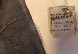
The images above show the components that are inside the pressure sensor, the conductive thread I’ve used to sew most of the circuit, and the glue I used to seal any knots I tied in the conductive thread. Conductive thread is quite determined to untie itself, so the glue is an attempt to stop that. The glue has been on there for a few days now, and it is still sticky enough to adhere to other pieces of fabric, so I might not use that again.
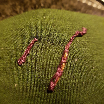
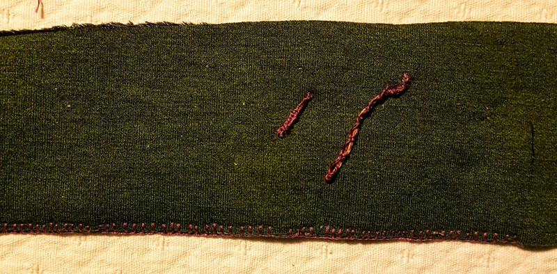
soldering the copper fabric#
So, I mentioned the datasheet for the copper taffeta earlier…
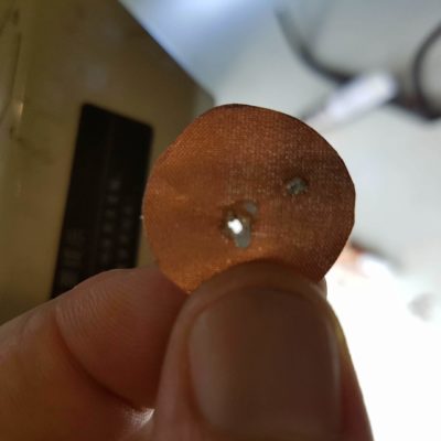
It’s not the longest datsheet I’ve ever seen, but it does have some crucial information in there, which is the temperature range. The first pad I soldered was exposed to higher temperatures for a longer time than the short term recommended by the datasheet. You can see the effects of that above. Even though I read that, I still wanted to see it myself. And actually, the pad still works.
The alternative would be to sew conductive thread to the pads, but I’d never soldered fabric before so I wanted to try it. I don’t know if you can tell in the image above that the copper thread is five or six ply - it’s probably clearer in the first image. Anyway, I had to burn off the coating it has before I started soldering, and it unravels when you do that, making it a little difficult to ‘tin’. You can see that I soldered the threads in two or three places so that I wasn’t relying on one solder joint.
creating the circuit#
After our session with Emma, I drew up a couple of circuit diagrams for this sensor. I remember the moment when I realised that I could understand a schematic. It was like breaking a secret code. It is a real abstraction from the physical outcome. To some degree, so is a circuit diagram, but it is slightly more accessible to a novice. To demonstrate that, I include an image of each, side by side below. I didn’t draw a schematic for this project. The circuit diagram is on the left (or first if you’re viewing mobily), and also, I made the bottom of the two diagrams, as I found some neopixels.
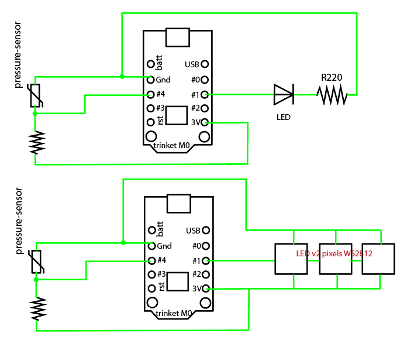
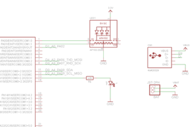
I appreciate that you might not be able to see a big difference between the two images, and that’s partly because of the symbols. I have annotated them (mostly) in the diagram, but you might find this website useful if you want to know more. Of course, the US has their own variations and I actually used their resistor symbol, so they’re obviously colonising this as well.
The diagram helped me immensely to work out how to join the components together. If didn’t have that as a reference when I was making the actual sensor, I could have been quite confused. You can see below that masking tape also helped me enormously. These things are fiddly… again, I didn’t want to sew it all together until I had tested that it all worked. Also, the image of the actual circuit below obviously isn’t as tidy as the circuit diagram…
Also, the resistor in there is a 20K one - I got someone else to press the sensor a few times and worked out the range of resistance was between 36K and 5K, so 20K was the closest match handy for dividing.
So I played araound with a bit of code, and it worked pretty well. I started by running a serial print to see what readings I got. Then using those, I hacked together some if-else statements with some existing neopixel sample code. As I said earlier, you’ll find the code here.
If the video isn’t loading and says you have to download it, refresh the page instead…
Next step: sewing it all together neatly…
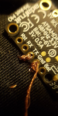
hard and soft connections#
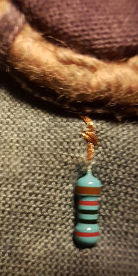
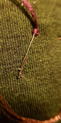
I haven’t been too adventurous with the connections so far. I will try out more as I go - this E-textiles Cheatsheet from Kobakant will be super-useful. You can see below that I pushed the legs of the resistor through the fabric, and then did two kinds of finishing; one by twisting the leg around the needle and one by binding the thread around it. I was using that leg as a jumper, in case my trace from another lead had come through the neoprene.
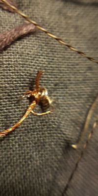
I had to jump the copper thread to one of the legs of the trinket too, so I bound it in a similar way and ran it at the same angle. This is where I could have planned better, but…it works. I sewed the pins on the trinket with two kinds of thread, and you can see that the copper thread is quite bulky. I sewed them through 3 x, same as the stainless thread, but I probably didn’t need to.
the completed circuit#
And this is what it looks like now, with the beginnings of some blanket stitch to close it. The front:
The back:
I appreciate that rather than creating a swatch I’ve created a complete circuit, but I really couldn’t wait until e-textiles II to see it finished!
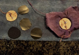
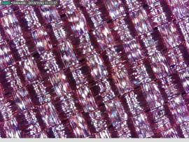
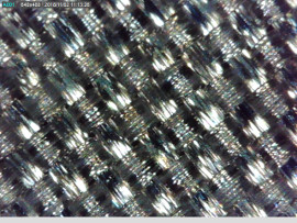
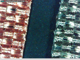
microscope photos#
While I was visiting Jean-Marie, I was playing around with coding my pressure sensor and he asked about the materials in it. I had some spare scraps with me, so he put them under the microscope and we took the photos below. The first of the copper taffeta, one of the ripstop and the last photo is of those two materials on top of the velostat. Super nice to see them in this way - loving the patterns a lot. They might inspire something else… I did try running them through image2surface in Textile Scaffold week, but ended up getting better results with another image.
download files#
bonus section#
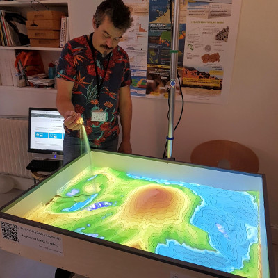
This week’s adventure extended to Switzerland, where I visited Jean-Marie at the SDG Fab Lab.

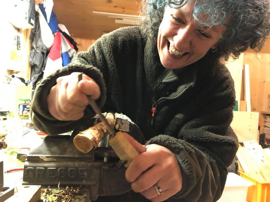
I also visited David Ott & the unofficial Fab Lab OTT, where I got to laugh a lot with friends and play with some great tools/toys in the Swiss Alps.
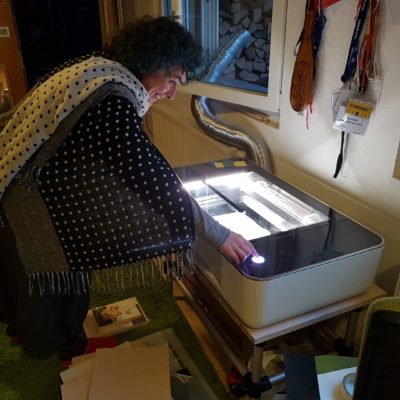
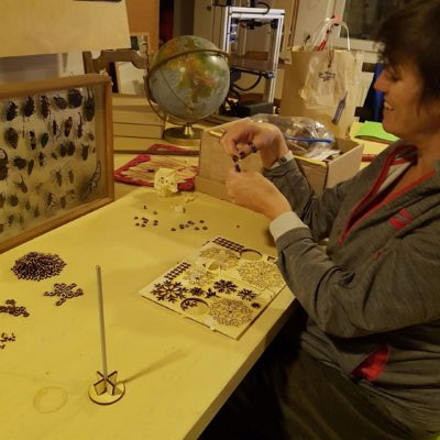
…Digital and handtools…
And this week I discovered that I could embed images from other websites in my webpage, the same way as I do when I add local images, using Markdown. I’ve never had to before, so I’ve never thought about it. As long as you have the website link that ends in the file extension of the image, you’re able. Also, I found a way to embed videos from google drive into my website, following this guide. And embedding videos from instagram following this guide