how to make the GIY incubator#
Although I started differently, it was because I was developing and iterating the idea, where I needed to do each aspect according to what I was focussing on. I recommend that you follow these workflows:
Read everything first - > ensure you have the electronics inventory in the lists below - > gather/order your other materials
If you need to make a fabISP, do that first - > make the main board and the temperature sensor -> populate the boards -> check the main board for continuity -> upload some test code to it ->
Make your casting moulds -> make the heater elements -> solder the 10 amp flex to the traces -> cast the silicon in the initial shape - > -> demould and cast the outer rectangle shape -> test the heater elements using the benchtop power supply -> test the temperature sensor with the heater
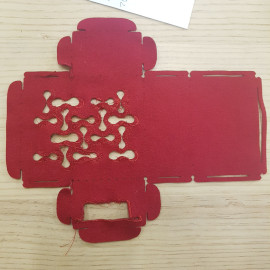
Infuse wax into the canvas material -> laser cut the sides, lid and base element -> laser cut the bamboo elements -> laser cut the wool elements -> leave the extraction going and the wool in the laser cutter for as long as you can. Like any animal product, it smells horrible when burnt.
Sew the lid components together -> crochet the hooks for hanging the bamboo rack from.
Sew the base components together -> remember to include the bullet clip as you sew.
Put together the power supply -> make a cover for it -> (include a fan or heat sink)
Insert heater, LCD screen, potentiometer and temerature sensor -> program your board with the code supplied and plug it all together -> check everything -> power it up and see what you can grow.
(Glitch)knit the jersey to give it extra insulation if you need it, and 3D print the flexible TPU buttons to hold it in place.
the electronics: boards#
Starting with the stuff that needs the most troubleshooting…all prices are in New Zealand dollars. If there are numbers in the link column, they’re the digikey part numbers. Search for these using your preferred search engine and you will also find the datasheets associated.
for the main board:#
| Qty | Description | Price/unit | Link | Notes |
|---|---|---|---|---|
| 1 | attiny 44 ssu | $1.28 | ATTINY44A-SSURCT-ND | Make sure you have a few on hand |
| 1 | 2 x 3 header/AVRisp | $1.35 | 609-5161-1-ND | |
| 1 | 2 x 5 header | $1.72 | 609-5163-1-ND | |
| 1 | 1uF Capacitor | $0.55 | 445-1423-1-ND | |
| 2 | 10K ohm resistor | $0.16 | 311-10.0KFRCT-ND | |
| 1 | 150 ohm resistor | $0.16 | 311-150FRCT-ND | not in inventory |
| 3 | 0 ohm resister | $0.16 | 311-0.0ERCT-ND | |
| 1 | green LED | $0.55 | 160-1169-1-ND | |
| 1 | tactile switch | $1.72 | SW262CT-ND | |
| 1 | n-ch mosfet 50V | $2.14 | RFD16N05LSM9ACT-ND | |
| 1 | LCD screen 16 x 2 | $15.64 | 67-1781-ND | |
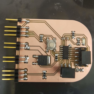
| 11 | header pins, horizontal | $6.86 | S1143E-36-ND | this price is for 36 |
| 1 | FR1, small, single | $1.40 | http://www.globallaminates.com/ | 75 x 50mm, fits the temp sensor as well |
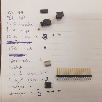
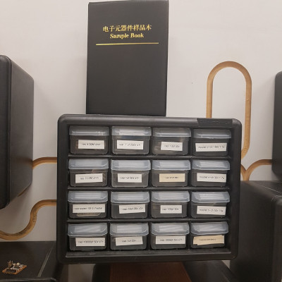
I write up a list and get all my components on a tray, like below - some people use a bit of double-sided tape to keep them in place but I (mostly) trust myself not to sneeze or shake. You can see that we have drawers with the components in them, but I also have a sample book that Felix Ma gave me, for resistors that aren’t in stock.
 )
) 
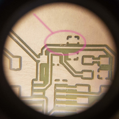
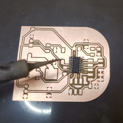
I check the board before I start soldering. I’m looking for any ‘swarf’ or stray threads of copper that are going to stop my board from working. You can see below that I found some, which I removed using a wire brush and tweezers.
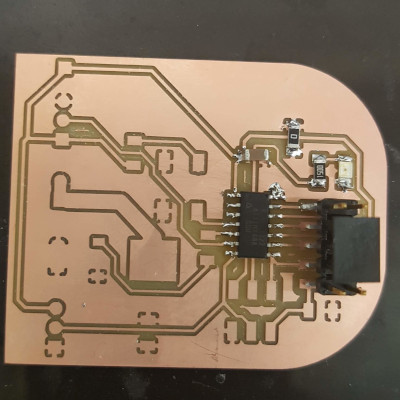
I make sure I haven’t had too much coffee and that I’m not hungry, because I always start by soldering the hardest part first. This is usually the attiny. Everyone has their own way of soldering - I’m left-handed and I go in a clockwise direction. I use a tiny tip when I’m soldering the attiny, and then use a bigger one for the other components. I also put quite a lot of solder on anything that is a connector, as it will be under some strain.
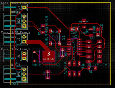
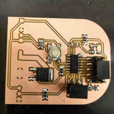
There are only two components on this board that could go around the wrong way - the attiny and the LED. Please pay attention when you solder these in place. It sucks to get that wrong.
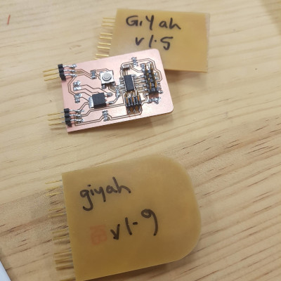
I write on the bottom of the board, which version it is, so I don’t get confused. Even though you’re not developing the board, I recommend that you do this also. You’ll remember that in another week, I couldn’t find my fabISP, because it looked a lot like the others lying around.
for programming:#
- a laptop or desktop computer with the Arduino IDE installed on it
- a programmer. I use this one that I made 7 years ago.
- depending on your operating system, you may need to install a driver for this. Check the Fab Academy archive for documentation on this.
- a cable to connect your programmer to your computer, and one to connect your board to the programmer
If you need to re-program it while it’s in the incubator, unplug the heater element and the LCD screen first. This is because the LCD screen shares some of the pins on the attiny, so it won’t work when they’re both plugged in.
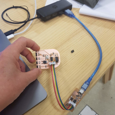
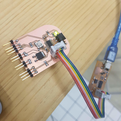
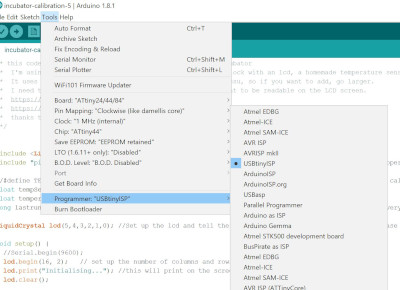
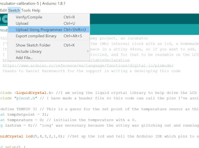
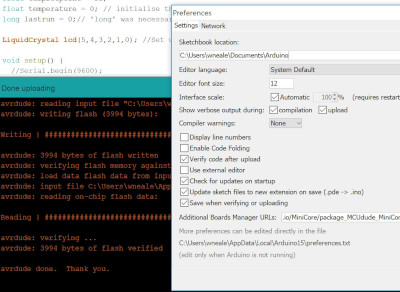
Using the code I’ve provided, choose what programmer you’re using, select the attiny44 as below, with the 1Mhz internal clock and upload your code. If it doesn’t work, it’s super helpful to go to preferences and enable verbose output so that you can see useful error messages. This code uses 97% of the available space on the attiny, so if you want to get fancy with your code, you’ll have to go bigger.
for the temperature sensor:#
| Qty | Description | Price/unit | Link | Notes |
|---|---|---|---|---|
| 1 | thermistor | $4.93 | 235-1109-1-ND | |
| 1 | 10K ohm resistor | $0.16 | 311-10.0KFRCT-ND | |
| 1 | 6K ohm resistor | $0.16 | 311-12.0KFRCT-ND | I used 2 x 12K ohm resistors, not in inventory |
| 1 | 277 ohm resistor | $0.16 | 311-280FRCT-ND | not in inventory |
| 3 | F2F breadboard leads | $X.00 | not in inventory | |
| 3 | header pins | $X.00 |
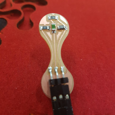
You can see that the temperature sensor is fairly simple. The layout comes from the datasheet of the thermistor, and the shape reflects the pattern on the lid of the incubator. The 2 12K ohm resistors are stacked on top of each other in parallel to create a 6K ohm resistance.
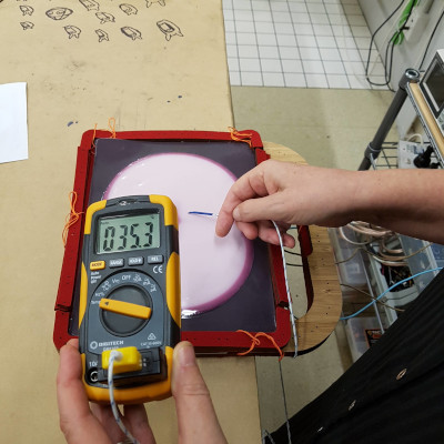
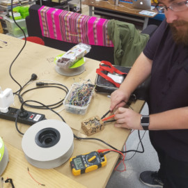
Here, you can see how I’m testing the temperature sensor by touching the thermistor and seeing the difference in resistance.
for the potentiometer:#
| Qty | Description | Price/unit | Link | Notes |
|---|---|---|---|---|
| 1 | potentiometer | $2.76 | https://nz.rs-online.com/web/p/products/7377776/ | not in inventory |
| 1 | 1K ohm resistor THT | $X.00 | not in inventory | |
| 3 | F2F breadboard leads | $X.00 | you will cut one end of these and solder |
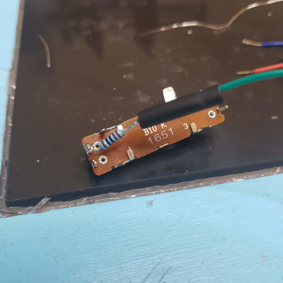
I added the 1k ohm resistor to the signal line as without it, the potentiometer goes to 0. You can see I’ve also put a small sleeve of heatshrink over the wire to protect and cover it when I’ve done that.
Reading the values of the temperature sensor to match them with the potentiometer wasn’t possible using the serial print function in arduino with the attiny, so instead we used the LCD screen to print the values.
void loop() {
  // if it's been 2 seconds since the last time the attiny checked, turn on and off the LED, call the temp control and print to the LCD screen:
    if(millis() - lastrun >= 2000){
      digitalWrite(STATUS, !digitalRead(STATUS));
      tempControl(); //call the tempcontrol routine below on heater for defined setpoint.
      lcdPrint(); //print what it found.
      lastrun = millis();//capture the time it last ran, so that we can compare snapshots.
    }
}

void tempControl() {
  // check what's going on on the temp pin, if the temperature is too high, turn off the heater, otherwise, it goes on
  int currentTemp = analogRead(TEMP);
  if (currentTemp >= TEMPSP) {
    digitalWrite(HEAT, LOW);
  } else {
    digitalWrite(HEAT, HIGH);
  }
  temperature = currentTemp;
}

void lcdPrint() {
  //start from the top corner of the LCD, print whatever's in the "", the second one is calling the currentTemp
  lcd.setCursor(0,0);
  lcd.print("therm val");
  lcd.print(temperature);
}
And took notes of lots of this:
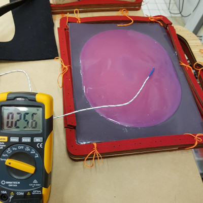
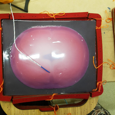
Underneath the pliers and masking tape (nothing sticks to silicon, except dust) is the temperature sensor and the temperature wand from the multimeter, stuck together with kapton tape so they’re as close together as possible for accurate reading of temperature.
for the heater element:#
| Qty | Description | Price/unit | Link | Notes |
|---|---|---|---|---|
| 2 | FR1, single sided, large | $5.60 | http://www.globallaminates.com/ | |
| 1 | foodsafe silicone 200ml | $89.95 | https://www.smooth-on.com/products/smooth-sil-940/ | price is for 1kg |
| 2 | thermochromatic pigments | $15.60 | http://www.mindkits.co.nz/store/p/6505-Thermochromatic-Pigment-Black-20g.aspx | price is for 20g |
| 1 | 2mm x 600 x 400 acrylic | $8.60 |
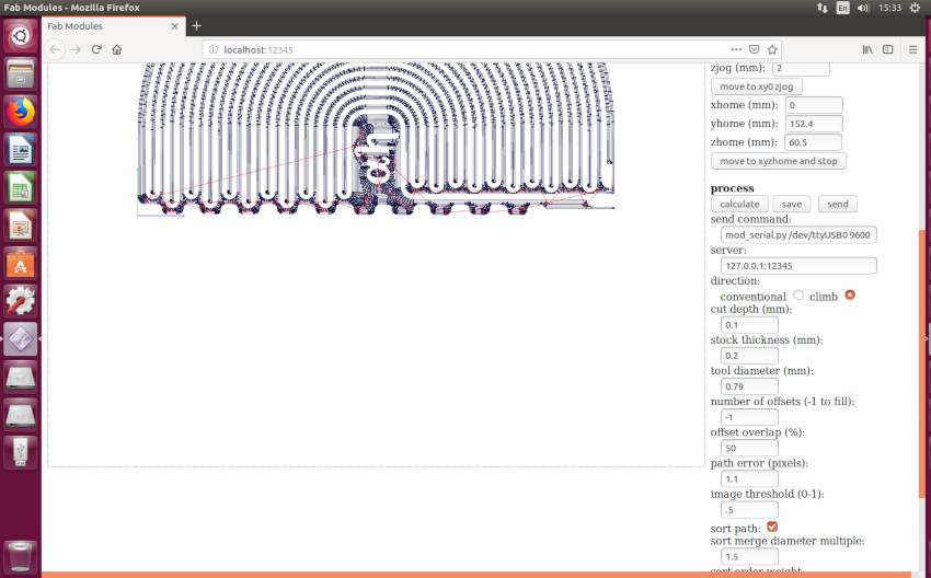
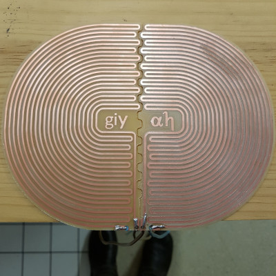
You will find the two PNGs in the zip folder to cut the two heater elements. Solder the heavy gauge wire to the ends. NOTE that the settings for milling this heater are using a 1/32 millbit, not a 1/64 millbit, with a cut depth of 0.1mm, material thickness of 0.2mm (I am lying to fab modules so that it will do what I want) and the number of offsets -1.
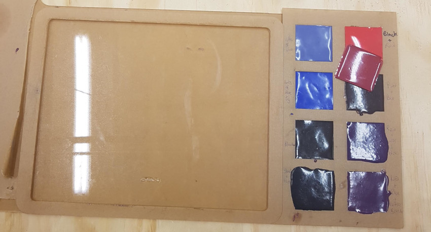
Make the first mould for the silicone using the 2mm acrylic, position the heaters, and start casting. I forgot to take photos of it in the first cast, and I used it for something else, so I’ve only got the second mould to show you. you can see where the holes are drilled for the wires to go through, and the squares I used for casting colour samples.
This silicon is 40 shore hardness, very viscous and has a short pot-life. I did it in three lots and spread it with a knife. Leave it to cure, then de-mould and position your cast into the second mould. Cast your second colour. I did this in one go. I wanted minimal silicon but full coverage. It’s up to you what you want, as long as the solder joints are completely covered.
When the silicon is cured, test your heater.
for the system:#
| Qty | Description | Price/unit | Link | Notes |
|---|---|---|---|---|
| 1 | 5V 5 amp power supply | $X.00 | don’t know | |
| 1 | wall plug | $X.00 | cut off a kettle cord | |
| 1 | 10 amp mains flex | $X.00 | cut up from same | |
| 1 | bullet plugs | $4.50 | https://www.jaycar.co.nz/2-pin-bullet-type-plug-socket/p/PP2034 | not in inventory |
| 1 | 100mm length of 1/8 inch heatshrink | $2.29 | A018B-4-ND | price for ~3mm x 1200mm |
| 1 | 100mm length of 1/4 inch heatshrink | $3.47 | A014B-4-ND | price for ~6mm x 1200mm |
| 5 | ferrules 1.5m2, 8mm, red | $13.47 | Utilux FE1508-RD | price for 100 |
Setting up this was my most serious task. The power supply plugs into the wall, and converts the 240V into DC 5V, so I wanted to make sure I did that very well. Once I was happy that no wires were exposed, I had them in all the right places and that the screw terminals were tight, I handed it over to Daniel for checking, as he is a registered checker-er of electrical appliances.
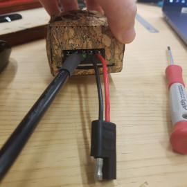
I made a cover for the power supply out of the cork fabric I used in Circular Fashion, as it was fairly structural with a woven backing. Initially I tried the waxed canvas, but it frayed, then I tried a boiled wool with digital embroidery, but that wasn’t structural enough either. Also, I messed up the alignment of the pattern… I recommend that you create a more functional cover - one that stops people from poking a screwdriver in it when it’s live.
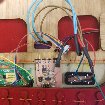
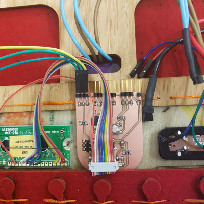
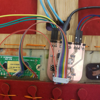
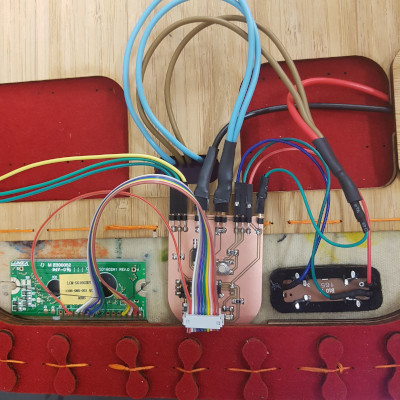
Then I plugged it all together. You can see in the photos below, the red power line comes in from the power supply and joins the brown wires from the heater. There’s a green signal wire coming out from that bunch and going to power the board. The black ground wire comes from the power supply and plugs into the board, the blue wires come from the heater and connect in the same way. On either side of this, the potentiometer and the temperature sensor are connected, and the LCD connects at the bottom of the board. There’s quite a lot going on, isn’t there?
for making:#
- a soldering iron & solder & suitable extraction
- an MDX-20 (or similar) to mill out the board, with 0.4mm & 0.8mm millbits and a computer to run it
- safety goggles
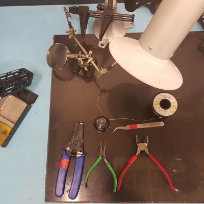
- tweezers, needle-nose pliers, side cutters, wire strippers
- wire brush
- a magnifying device and/or a loupe
- a benchtop power supply like an Instek GPS-2303
- a multimeter with temperature measuring capability
- an alfoil container, a mixing stick and some scales to weigh the silcone
for the body#
The Illustrator files have a number of named layers that should help you to create this. If you use different thickness materials to make this than I did, you may need to adapt the ‘hardware’ files accordingly. The base is a fusion360 file so you can use the slicer plug in to adapt it. If you’re making this using the SVG files, and are having touble working out which part is which, you could contact me.
There are three main components - the base, the lid and the sides - and there is a power supply cover. Cut them out and put them together. :)
(obviously I ran out of energy to thoroughly document this last bit, but I hope it’s fairly easy to work out yourself.)