5 | E-textiles
Ooh my dear electronic, it hasn’t been long since the last time! I still remember those long hour classes of despair, stress and the unknown, but also of self-improvement and the joy of being able to make circuits.
This week has helped me to review the knowledge that I had and add some new ones. To understand this assignment and this project, here is a short scheme summarising the basic concept:
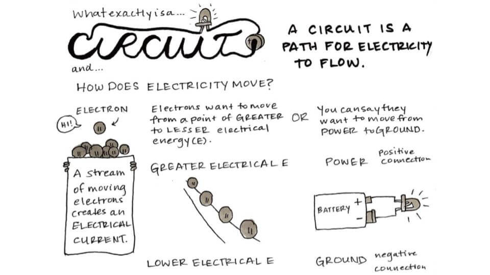
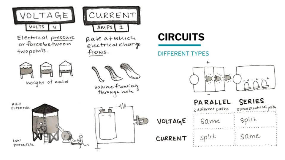
From Liza's lecture
Digital sensor
Inspiration
I’m passionate about the stars and conste, about the night and its “lights”. For that reason, I took it as inspiration for this project.
Due to light pollution, we are missing the opportunity to connect and enjoy what lies beyond the Earth. I wanted to represent its beauty at our fingertips.
I would like to switch off the lights of the Earth and switch on the lights of space.

I already had knowledge of electronics, so that’s why I have been a bit ambitious and I wanted to do a bit more than what was asked for in the assignment. For me, sewing was the real assignment, it has been with me on all my journeys. I draw the constellation with a chalk to use it as a guide. The two lines crossing the drawing would be use as positive and negative poles.
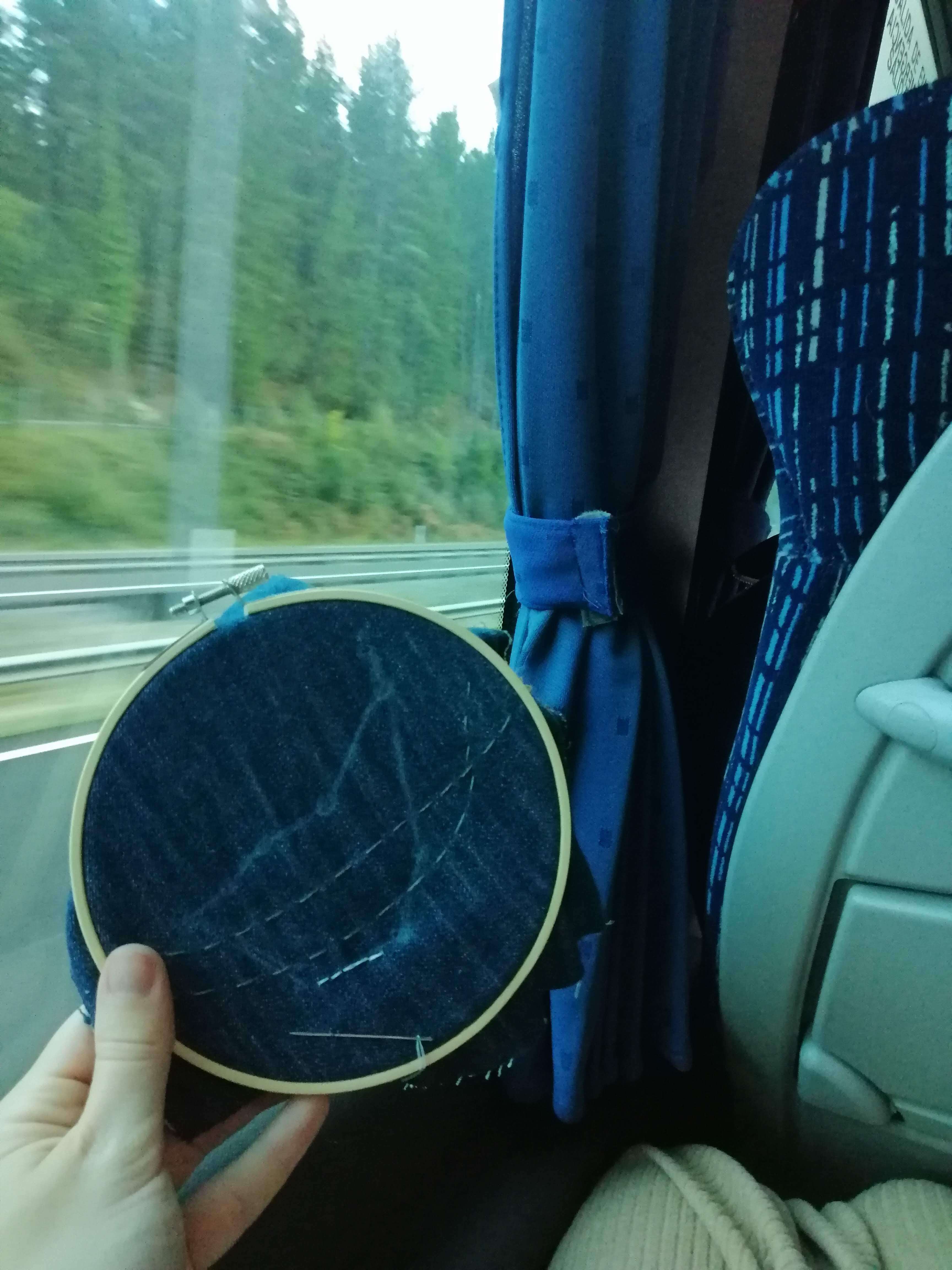
I wanted to represent the Capricorn constellation using 10 LEDs in different colours, which means different voltage values that I had to take into account.
Prallel circuit
This is the circuit and the components that I used:
-
3 white LEDs
-
4 blue LEDs
-
2 yellow LEDs
-
1 resistor of 220 Ohms
-
1 pushbutton (to simulate the soft sensor)
-
Power source
-
Jumpers
I started putting the LEDs in parallel. Because the lights are placed in that way, the voltage is added. Knowing the necessary voltage, I calculated the resistance that it needed.
I found a project that used 10 LEDs, as well, 9V and 35 Ohms, so I tried with those values.
I tried it before on a breadboard to check if it worked and this happened:

With 9V, only one LED worked, that means that it needed more power. However, the resistance didn’t support so much power and as a result, it burned (my mistake for not noticing).
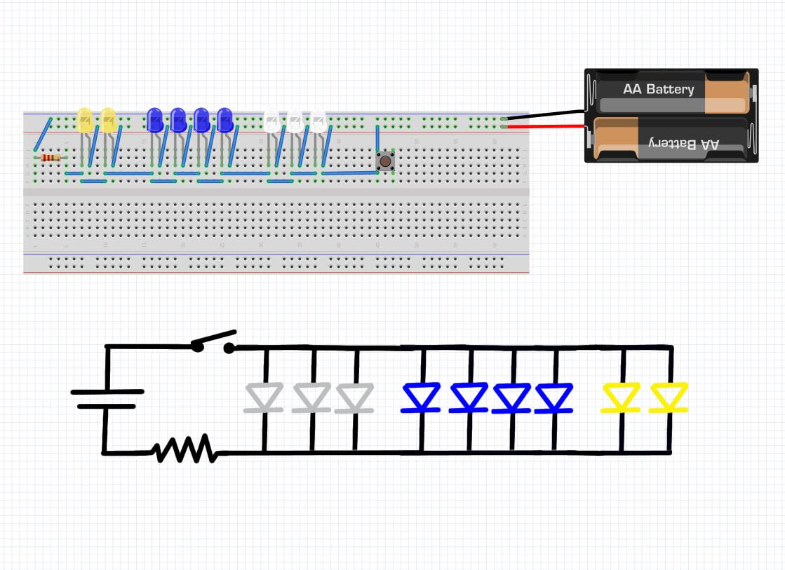
In view of the success (irony), I used 3 resistors, one for each group of colour LED. I used Inventable.eu, to calculate it.
So, this is the circuit that I made:
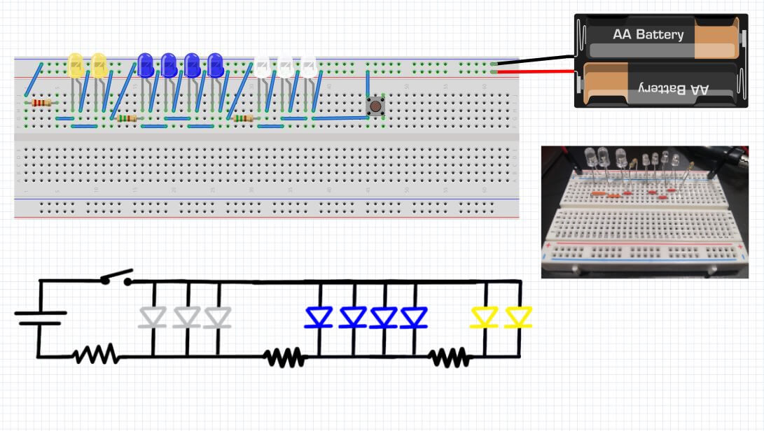
I put the components in groups (the LEDs and the resistor) on the beardboard, to check that it worked (and prevent from burning another resistor jeje).
It worked, so the “easiest” part was already done.
I started sewing a soft sensor, I used foam, neoprene, copper fabric, conductive thread and thread. The neoprene was to isolate and ensure that the conductive thread did not come into contact making a close circuit. Through the copper fabric is where the circuit will be closed.
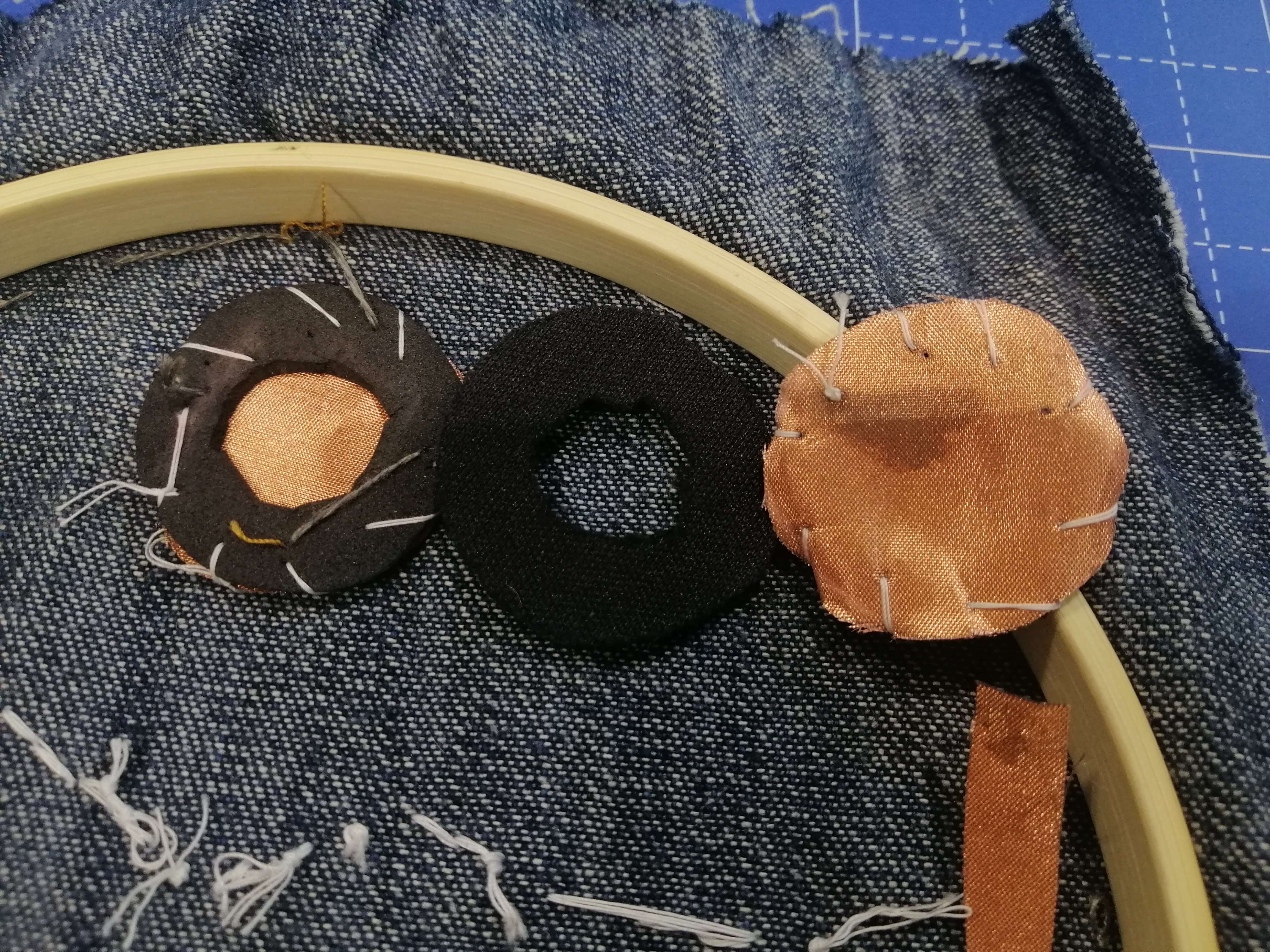 (Sorry for my bad sewing technique but it was enough to make it work!)
I sewed the first four components (3 LEDs and its resistor) to start and to check that it worked, because imagine sewing 13 and nothing works. Luckily I did it, because none of the LEDs switched on.
I supposed that the problem was in the way I sewed, there must have been a thread that was not making the right contact.
Series circuit
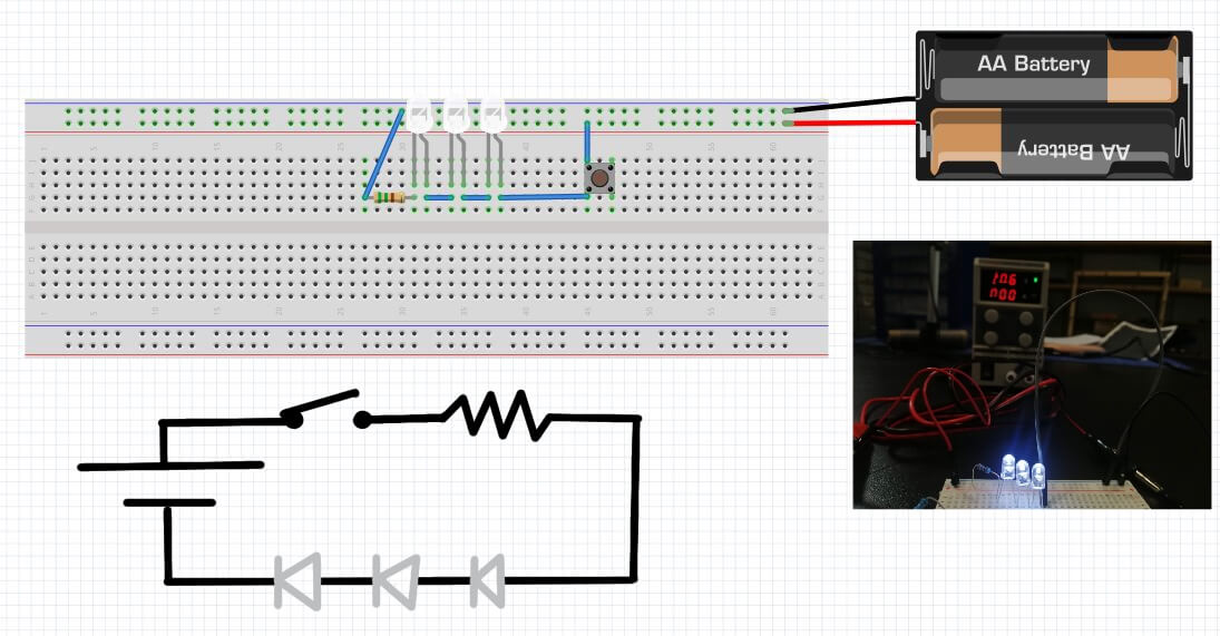
I couldn't waste much time , but I decided to give it a second chance. I used the same concept but I decided to make a series circuit with 3 LEDs and a resistor. I thought it would be easier to sew the connection.
So I repeated the same process: I assumed I would use 15V in order to calculate the resistor I had to use (550 Ohms) for 3 white LEDs. I checked it before on a breadboard and it worked, too.
Well, here we go again. It was time to sew! I was hoping that this time it would work because it was easier to sew it.
Finally, I got it!!! You can’t imagine how proud I was.
Analog sensor
It took me longer than I expected to make the digital sensor, for that reason I didn’t want to complicate my life with this circuit. I couldn't stand another failure… (jejeje I’m joking).
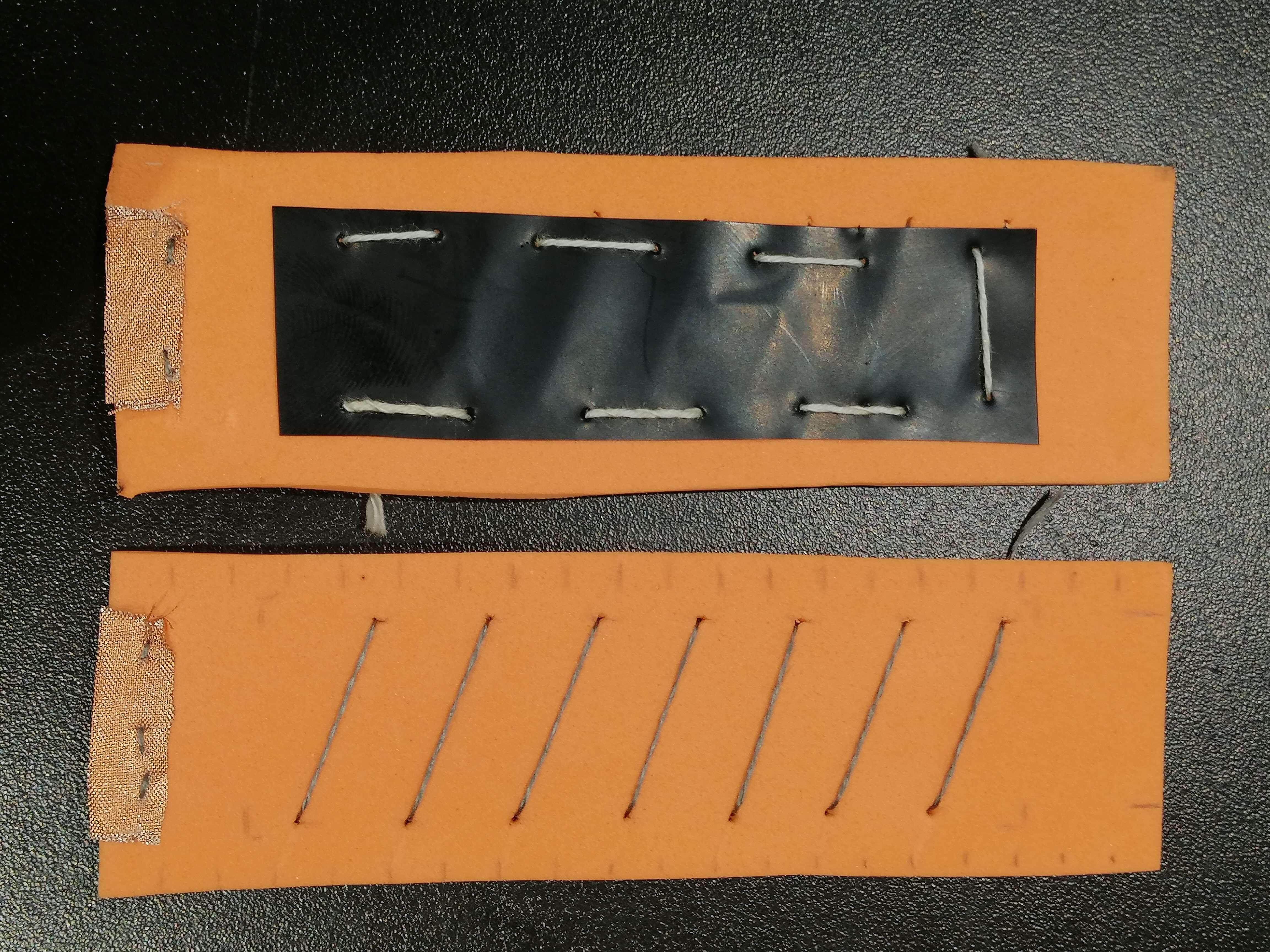
There were so many examples, however I took the Neoprene Bend Sensor project. Instead of neoprene I used foam. Following this scheme I built my soft sensor:
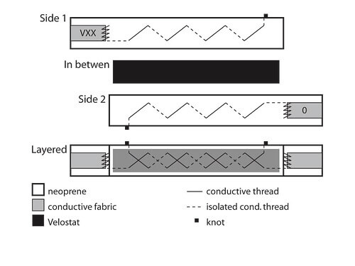
I did some marks to sew it properly and to ensure the two threads cross each other:
Finally, I built the circuit. It’s a simple one, because you only have to connect one sensor to an analogue readout on the Arduino and the other to GND. It had a resistor to protect the Arduino.
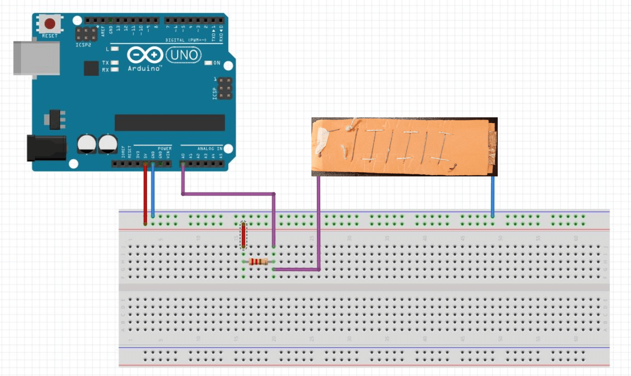
And this is the code I used. It is a code where it only shows the reading of values on the Serial Monitor.
int analog_sensor_pin = A0;
int analog_sensor_value = 0;

void setup() {

pinMode(analog_sensor_pin, INPUT);
Serial.begin(9600);

}

void loop() {

analog_sensor_value = analogRead(analog_sensor_pin);

analog_sensor_value = map(analog_sensor_value, 230, 130, 0, 255);
analog_sensor_value = constrain(analog_sensor_value, 0, 255);

Serial.println(analog_sensor_value);
delay(100);

}
Here we can see how the resistance value changes on the serial monitor.
And here we can see that this variation in resistance influences the brightness of the LED.