8 | Wearables
THE FIRST WEARABLE FOR PEOPLE WHO SUFFER FROM PANIC ATTACKS.
Context
In 2019, a study determined there were 3.83% people that had anxiety disorder, 275 million, over the world. There are different types of disorder, however, the common denominator is panic attack.
A panic attack is the sudden onset of intense fear of a situation that does not require danger. This malaise lasts between 5 and 20 minutes, although in a worst-case scenario, it can trigger a series of panic attacks lasting for hours. The pain that is felt can be confused with a heart attack.
The therapies currently available are classified into 3 groups: natural treatments, psychotherapy and psychopharmaceuticals. However, they may not be enough to treat them (in case of natural treatments), be expensive (psychotherapy) or have side effects (psychopharmaceuticals). Moreover, you can’t use them at the time of the attack.
As an alternative, I proposed to use an ancient therapy called chromotherapy.
This therapy is more than 5,000 years old. As its name says, it consists of curing illness and pain through the colours. 7 colours are used, the same ones as a rainbow.
It’s a non-invasive therapy, without the use of toxic toxic substances and no side effects. So, chromotherapy could be used as a complementary treatment to the treatment that a specialist has sent.
There are different ways to apply it: wearing clothes of one colour, a diet based on one colour, with light, with acupressure... To treat anxiety and panic attacks, I used the blue colour.
Blue colour
Blue is a pure colour. It belongs to the group of primary colours, those that cannot be obtained by mixing other colours.
This colour has always had a calming effect on people and has been scientifically proven. It has different benefits, such as being able to create a peaceful state in the central nervous system, reducing blood, pulse and respiration.
Visuddha
The therapy is activated when you slide the left piece down. A light will be activated and its brightness will change to define a rhythm to follow with the breath.
For the assignment, I needed to use 2 actuators and my original project has an open circuit that when you slide the piece down, the circuit is closed and activates the therapy. So, I used a LED controlled by a LDR module (when there is no light, the therapy will be activated) and a vibration mini motor (during the therapy it will be activated).
I scaled the principal piece, where the electronics components were located. I took as reference the battery because it would be the biggest component. Also, I did two holes to place the LDR and the LED.
This was the concept:
Codes
Divide-and-rule! That has been the key to reach the final code. I did the 3 functions separately, apart from some tests.
-
Function 1: If there is no light at all, the LED turns on.
-
Function 2: The LED on will change the intensity creating a pattern to follow with the breath. To appreciate when the LED is fading, there will be a blink.
-
Function 3: Vibrate when the therapy is is activated.
Test to check values received by the LDR module.
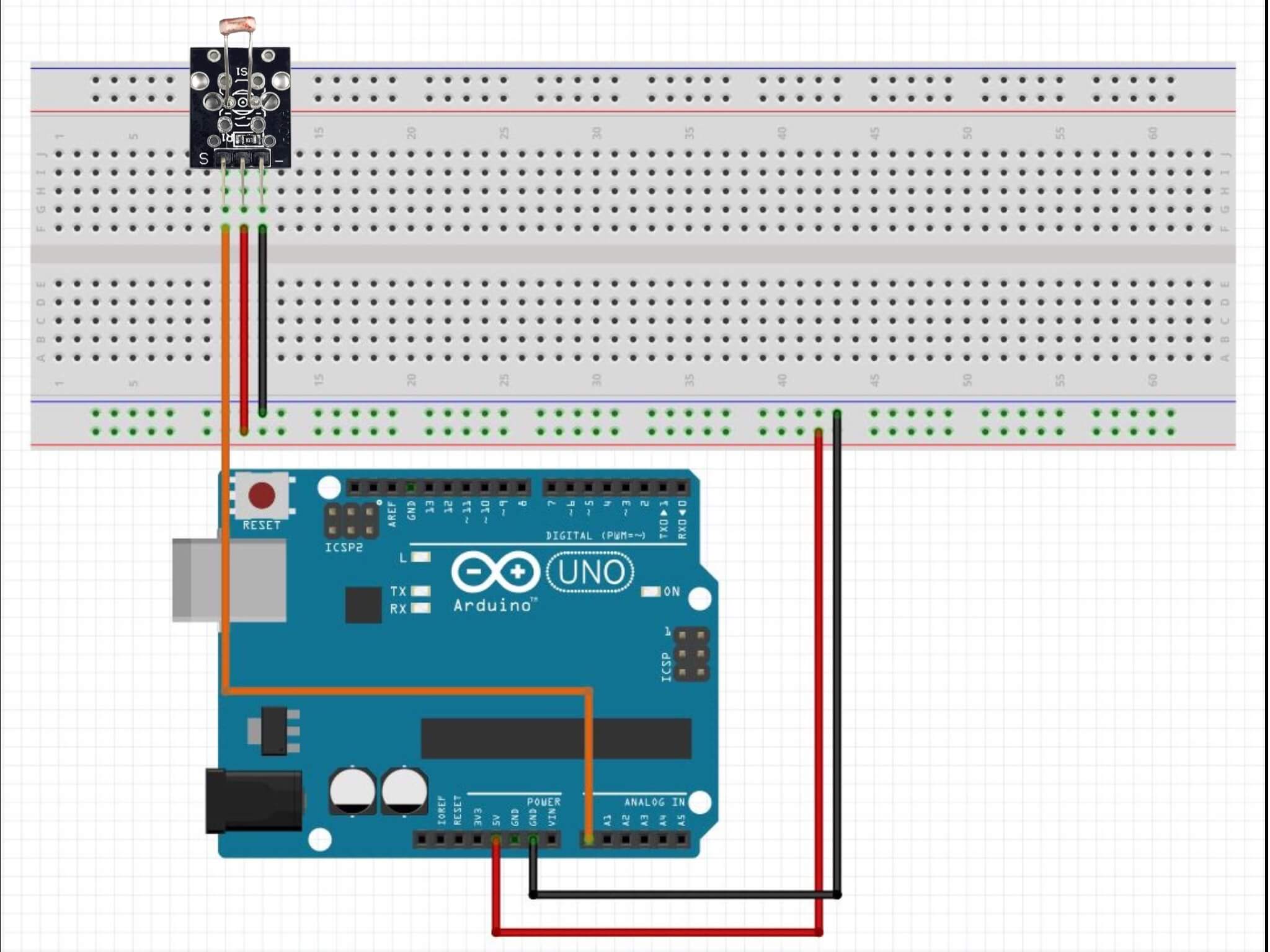
int lightValue;   // light = LDR sensor

void setup() {
  Serial.begin (9600) ; // Starts a connection via the serial port
  Serial.println ("Reading...");   // To find out if the function has been read correctly
  // ("__TEXT__") Any text can be placed between the inverted commas.
}

void loop() {
 lightValue = analogRead ( A0);   // Light value reading
 Serial.println (lightValue);   // Add the values read by the sensor to the serial monitor.

  delay (40);   // Always put at the end as this is the number of seconds it takes to repeat the action.

}
Results:
- With flash: 760
- With ambient light: 345
- Without light: 6
Code that simulates the rhythm of breathing.
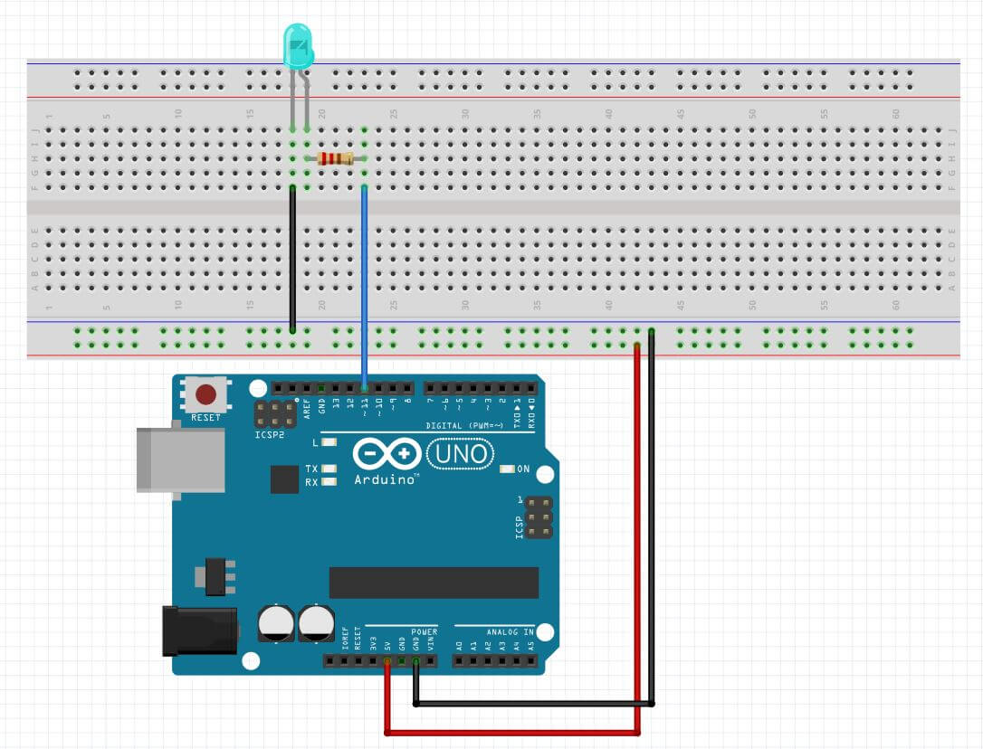
int led = 11;
int vled;

void setup() {
  Serial.begin (9600);
  pinMode(led, OUTPUT);
}

void loop() {
  for (vled=0;vled<255;vled++){   // Fade in
    analogWrite (led,vled);
    delay(15);
  }

// Blinking
digitalWrite(led, LOW);    // Turn the LED off
  delay(50);
digitalWrite(led, HIGH);   // Turn the LED On
  delay(50);

  for(vled=255;vled>0;vled--){   // Fade out
    analogWrite(led,vled);
    delay(15);
  }
}
Code to turn the LED on/off with the LDR module depending on the surrounding light.
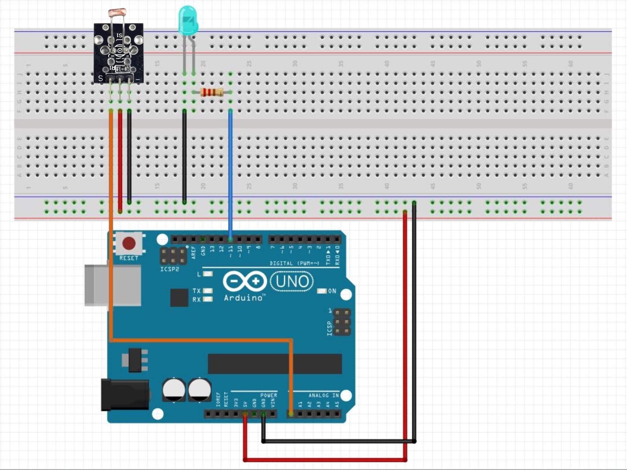
const int LEDPin = 11;
const int LDRPin = A0;
const int threshold = 760; // First code data

void setup() {
   pinMode(LEDPin, OUTPUT);
   pinMode(LDRPin, INPUT);
}

void loop() {
   int input = analogRead(LDRPin);
   if (input < threshold) {   // The condition: If the value received by the LDR is less than the threshold, the light turns on.
      digitalWrite(LEDPin, HIGH);
   }
   else {   // Otherwise it turns off.
      digitalWrite(LEDPin, LOW);
   }
}
Final code
1 actuator: LED
It is the same as the one I used for the previous code.
const int LEDPin = 11;
const int LDRPin = A0;

int vled;
const int threshold = 760;

void setup() {
   Serial.begin (9600);
   pinMode(LEDPin, OUTPUT);
   pinMode(LDRPin, INPUT);
}

void loop() {
  int input = analogRead(LDRPin);
  if (input > threshold) {
      digitalWrite(LEDPin, HIGH);

      for (vled=0;vled<255;vled++){
  analogWrite (LEDPin,vled);
  delay(20);
  }

digitalWrite(LEDPin, LOW);
  delay(50);
digitalWrite(LEDPin, HIGH);
  delay(50);

digitalWrite(LEDPin, LOW);
  delay(50);
digitalWrite(LEDPin, HIGH);
  delay(50);

for(vled=255;vled>0;vled--){
  analogWrite(LEDPin,vled);
  delay(20);
  }
   }

  else {
      digitalWrite(LEDPin, LOW);
   }
}
2 actuators: LED + Vibrating Mini Motor D
The vibrations increase the stimulus, too.
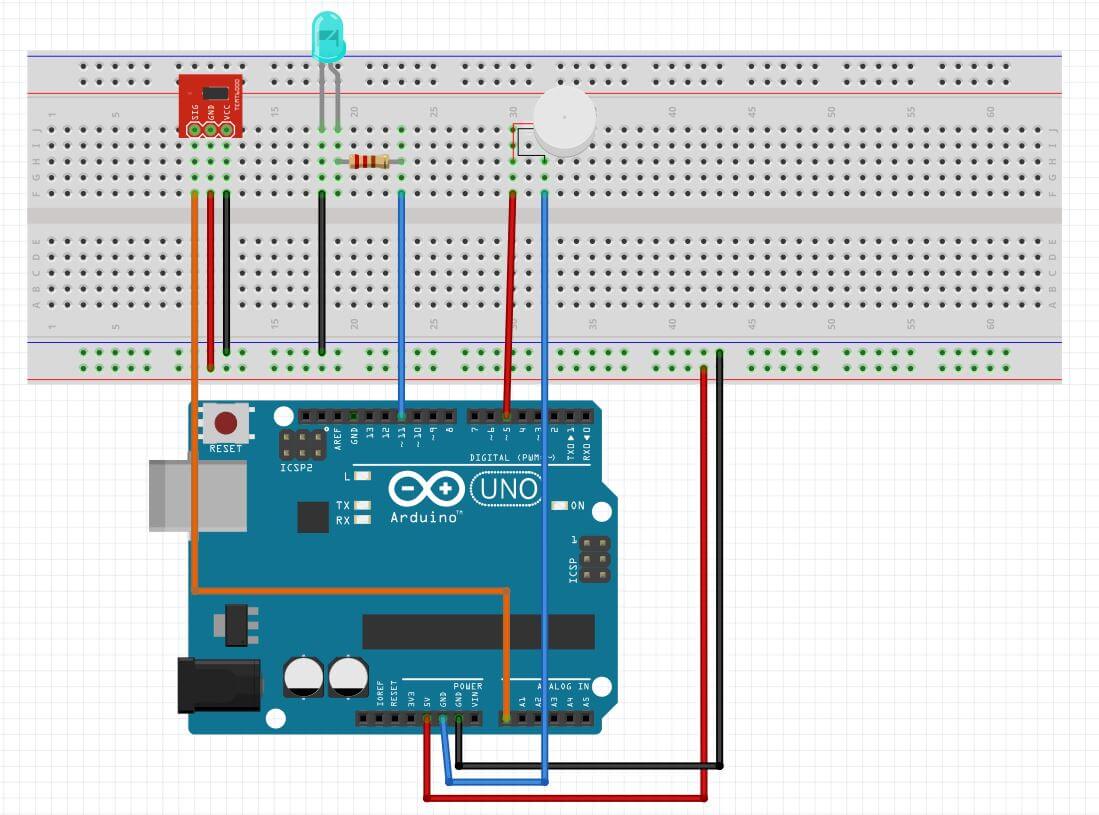
const int LEDPin = 11;
const int LDRPin = A0;

int motor = 5;  // Vibrating motor

int vled;
const int threshold = 760;

void setup() {
   Serial.begin (9600);
   pinMode(LEDPin, OUTPUT);
   pinMode(LDRPin, INPUT);
   pinMode(motor, OUTPUT);
}

void loop() {
  int input = analogRead(LDRPin);

 //Condition
  if (input > threshold) {
      digitalWrite(LEDPin, HIGH);   // Switch ON the LED
      digitalWrite(motor, HIGH);    // Switch ON the motor

// Fade in
      for (vled=0;vled<255;vled++){
  analogWrite (LEDPin,vled);
  delay(20);
  }

// Blinking
digitalWrite(LEDPin, LOW);
  delay(50);
digitalWrite(LEDPin, HIGH);
  delay(50);

digitalWrite(LEDPin, LOW);
  delay(50);
digitalWrite(LEDPin, HIGH);
  delay(50);

// Fade out
for(vled=255;vled>0;vled--){
  analogWrite(LEDPin,vled);
  delay(20);
  }
   }

  // Consequence
  else {
      digitalWrite(LEDPin, LOW);   // Switch OFF the LED
      digitalWrite(motor, LOW);   // Switch OFF the motor
   }
}
Attiny85
ATtiny is a microcontroller, as an Arduino, but with few features and fewer I/O (input/output) pins. For this project I used the ATtiny85 which has 8 pins. Each pin is assigned with multiple functions and it depends on the requirements of the project.
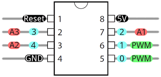
The pins 2, 3 and 7 are for analog pins, however you can use them as digital pins, too.
When you are coding in Arduino, you have to take into account that the name of the pin is those in red or blue.
If you connect a LED in the pin 5, in Arduino you have to declare it as int LED = 0; because the number 5 is just the physical position.
In the case of analog, if you connect a sensor in the pin 2 (physical position), you declare as int SENSOR = A3;.
To copy the code into ATtiny85, first you have to install the ATtiny driver. I followed this tutorial:
Once installed, it has to be set to be programmed in ATtiny85. I tried two ways: with an Arduino and with an USBTinyISP.
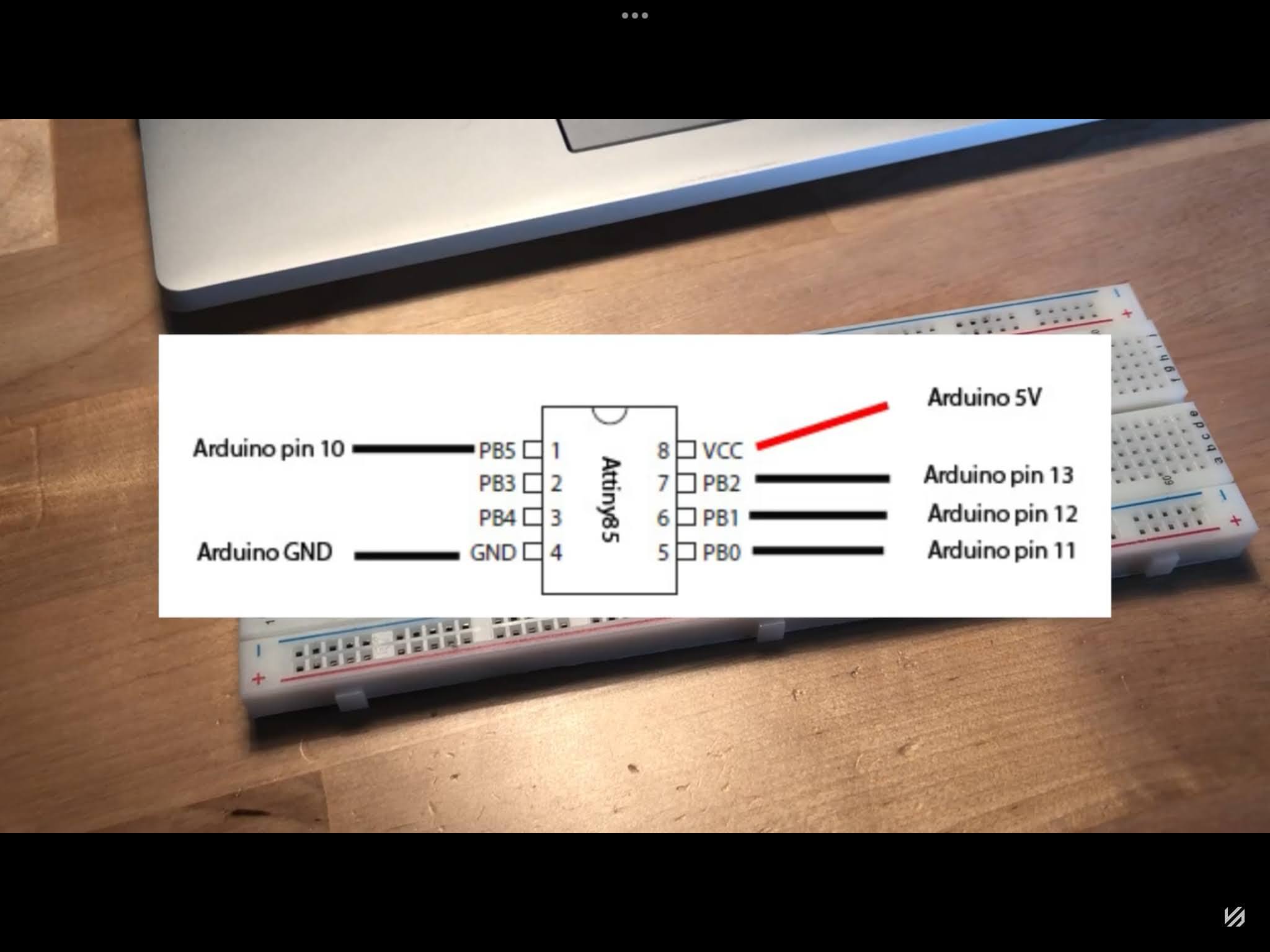
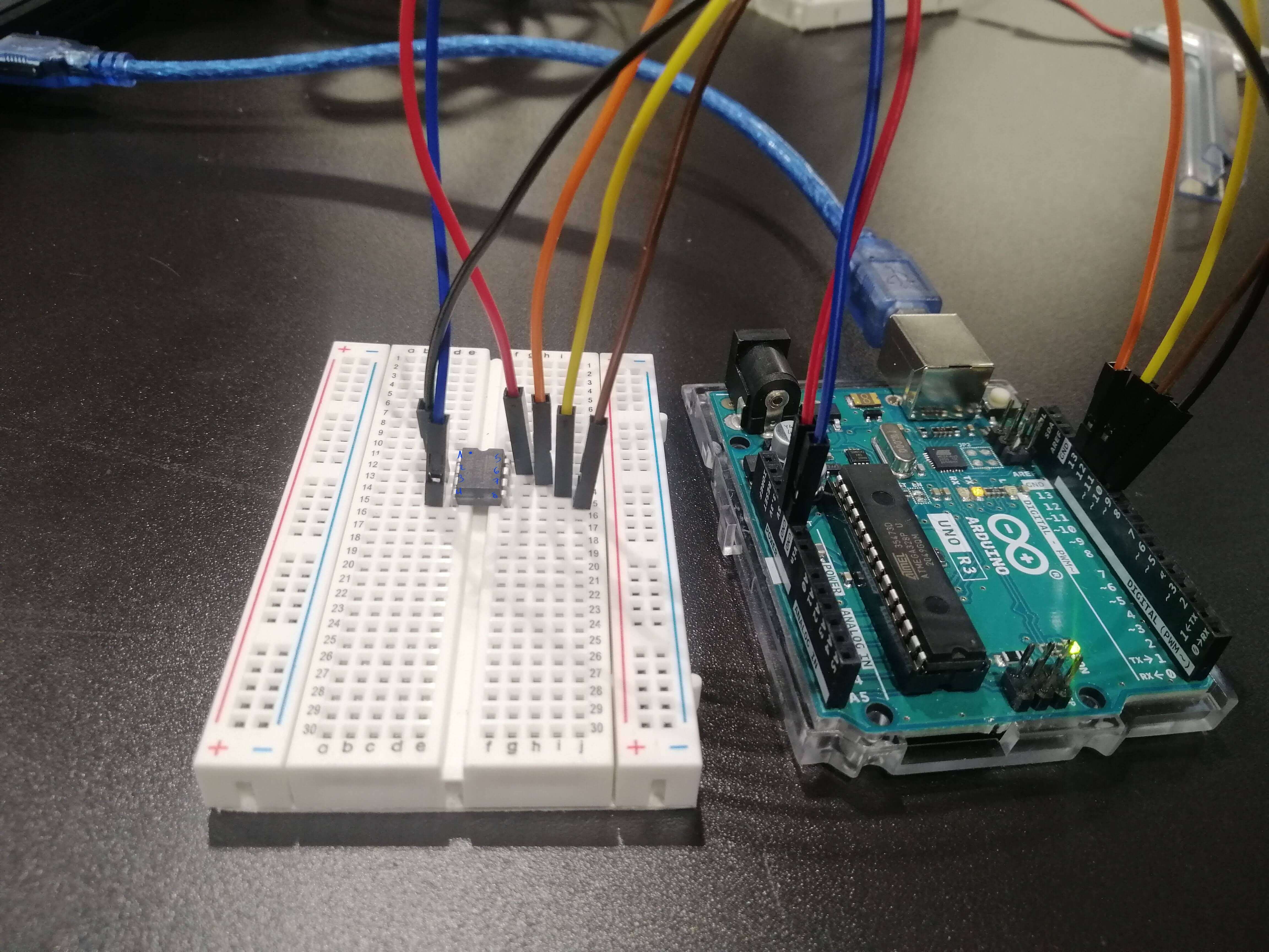
Program it with Arduino
Following this tutorial I did this circuit, how to program an ATtiny with Arduino. It is a more crafty way of doing it and may cause more problems. Obviously, it didn’t work. This is the scheme and the circuit that I did it.
Program it with USBTinyISP
As it did not work, I used an USBTinyISP. It’s really easy to use, you only have to connect the ATtiny85 to the board and then the usb to the computer.
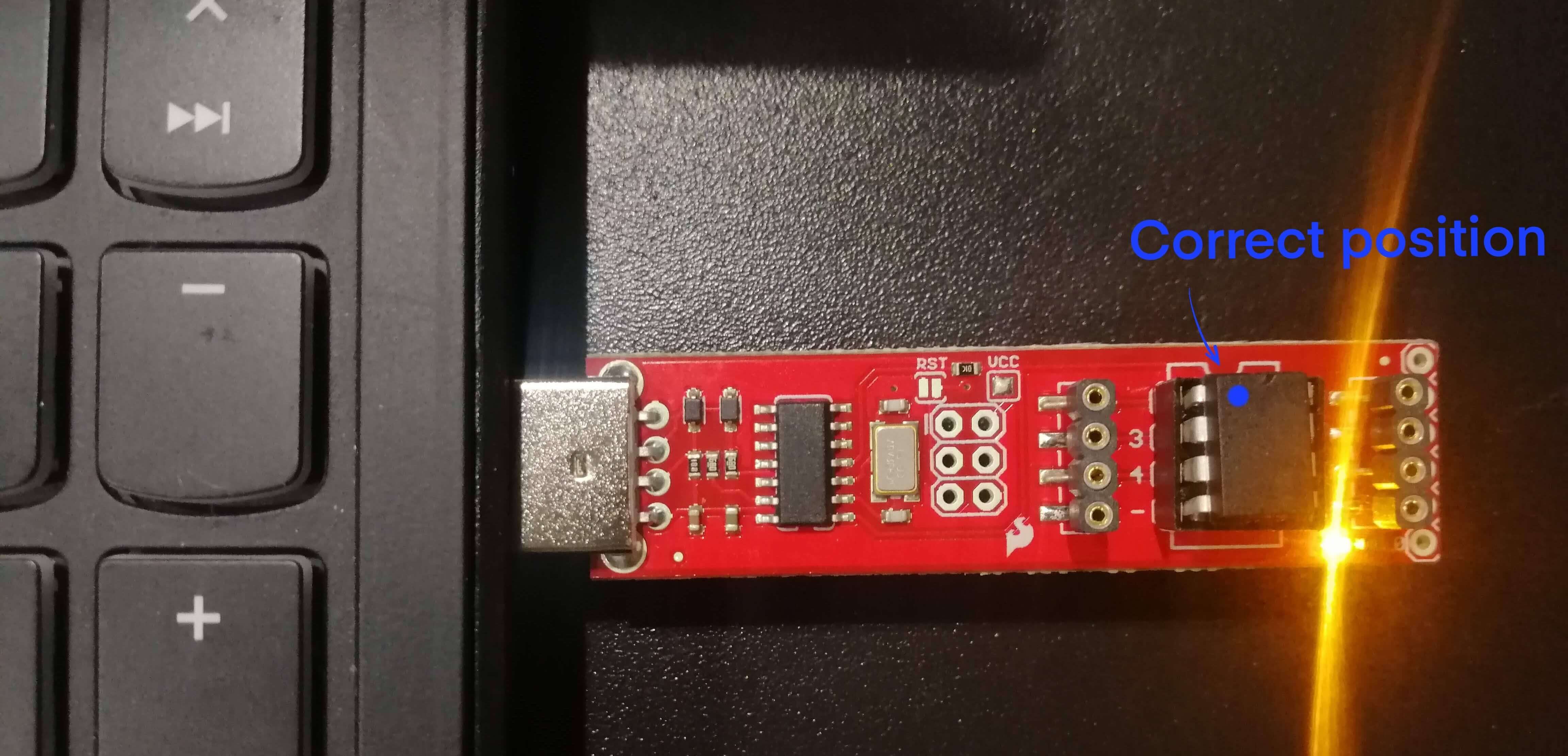
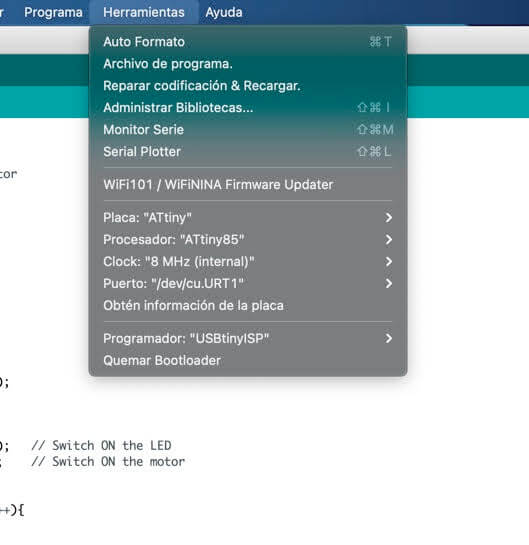
I followed this page, it's in spanish, but the most important thing is:
- Tools -> Board : ATtiny85
- Tools -> Programmer: UsbTinyISP
- Tools -> Burn Bootloader.
And these are the rest of the settings:
This is the circuit that I did with the ATtiny85 and a battery instead of using the Arduino as power source.

const int LEDPin = 0;   // Change the pin
const int LDRPin = A3;   // Change the pin

int motor = 1;  // Change the pin

int vled;
const int threshold = 760;

void setup() {
  // Serial.begin (9600); DELET
   pinMode(LEDPin, OUTPUT);
   pinMode(LDRPin, INPUT);
   pinMode(motor, OUTPUT);
}

void loop() {
  int input = analogRead(LDRPin);

 //Condition
  if (input > threshold) {
      digitalWrite(LEDPin, HIGH);   // Switch ON the LED
      digitalWrite(motor, HIGH);    // Switch ON the motor

// Fade in
      for (vled=0;vled<255;vled++){
  analogWrite (LEDPin,vled);
  delay(20);
  }

// Blinking
digitalWrite(LEDPin, LOW);
  delay(50);
digitalWrite(LEDPin, HIGH);
  delay(50);

digitalWrite(LEDPin, LOW);
  delay(50);
digitalWrite(LEDPin, HIGH);
  delay(50);

// Fade out
for(vled=255;vled>0;vled--){
  analogWrite(LEDPin,vled);
  delay(20);
  }
   }

  // Consequence
  else {
      digitalWrite(LEDPin, LOW);   // Switch OFF the LED
      digitalWrite(motor, LOW);   // Switch OFF the motor
   }
}
Prototype
I did the model in Rhino with a new dimension and then I printed it in PLA. These were the settings for the printing:

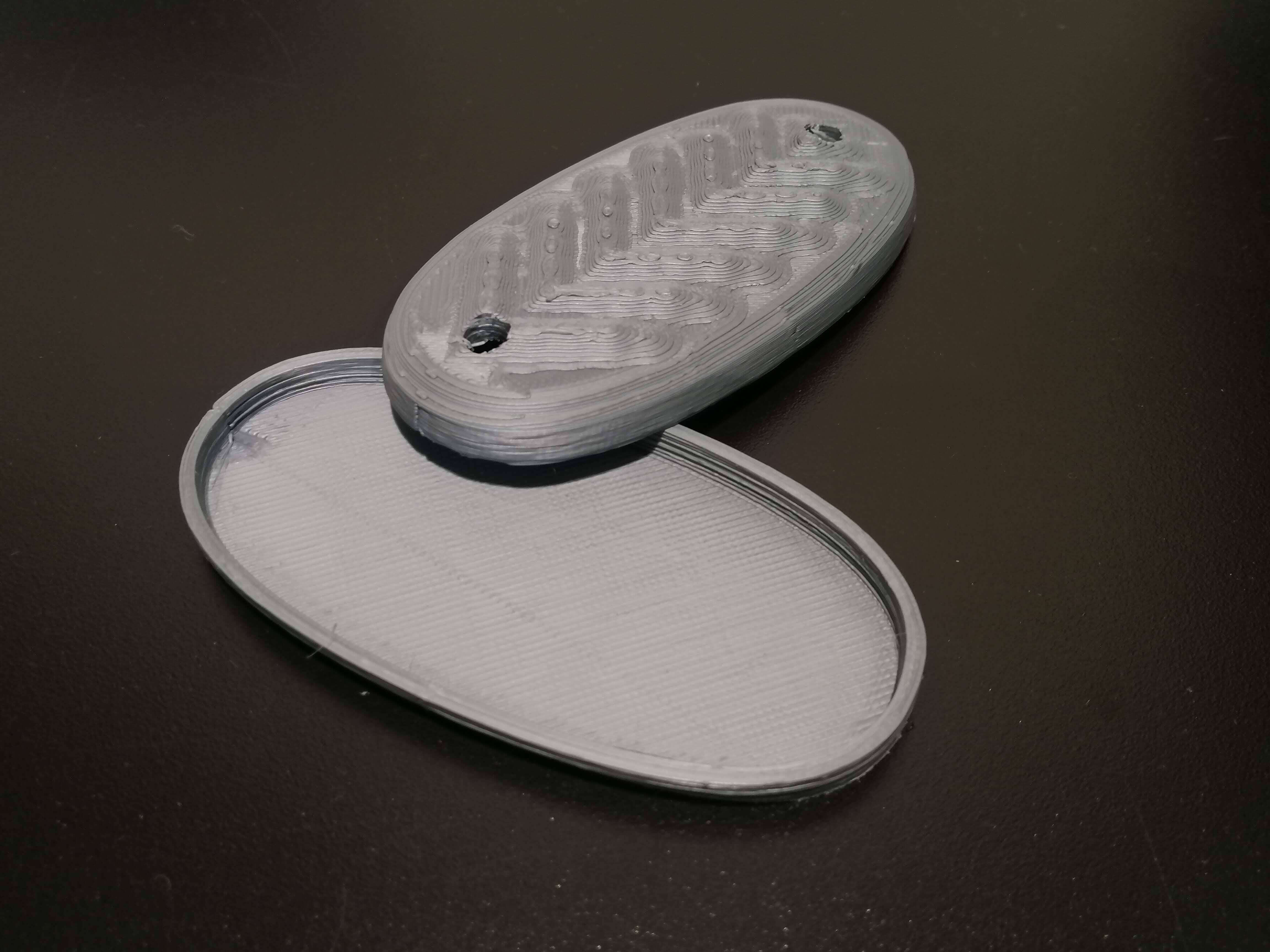
The next step would be to solder the components to a board.
Mosfet circuit
Useful links
I'm sorry but some of these links are in Spanish, but the diagrams and codes are very useful.