10 | Open Source Hardware - From Fibers to Fabric
HILO Spinning Machine 3.0
Studio HILO is a Berlin-based studio for textile innovation. We rethink textile manufacturing by offering training, consultancy and open-source tools for small-scale productions.
They have a section of "Open Tools" where they offer open knowledge on textile hardware and software enables experimentation, innovation and rapid prototyping for local yarn manufacturing.
If we wanted to make a machine, we had to understand how it worked each piece as a whole . For that reason, we checked other projects, such as Ana Correa’s, Lara Campos’ and Catherine Euale’s documentation. We had access to their files so we decided to choose one machine and built it.
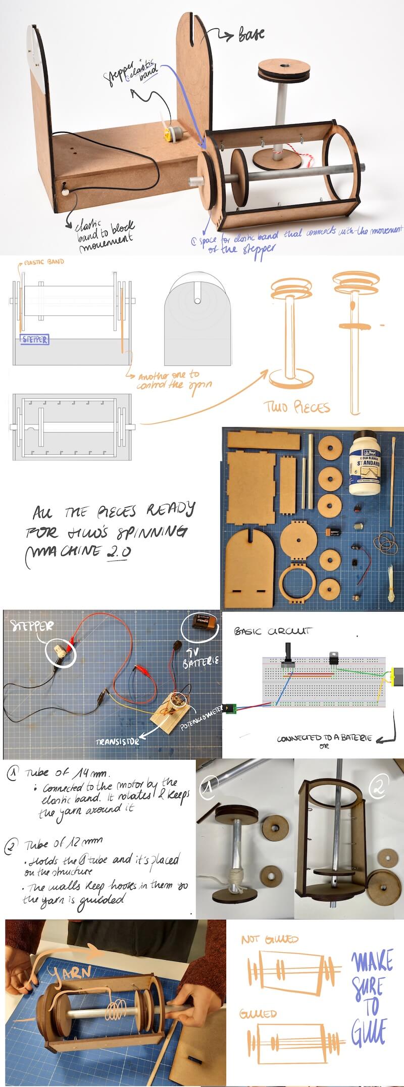
The first step was to cut the pieces. To save time, our instructors had already cut them. They cut them in DMF of 5 mm of thickness. The second step was to assemble them. It was quite difficult because there wasn't a “manual” or a section explaining how it should be assembled. With the basic plans and watching the 2 videos, I've even lost count of the number of times we've seen them, we finally built it.
The third step was to see if it worked. We weren’t familiar with the technique to transform the fiber into thread, for that reason we had some troubles. We used a wool thread to see if the machine would pick up the wool and roll it up. Finally, it worked! We learnt and understood how it worked to make improvements.
The electronics
We recibe a sketch of a circuit with a DC motor. DC motor that was connected to a transistor and a potentiometer and all of this had a 9-volt battery that supplied power.
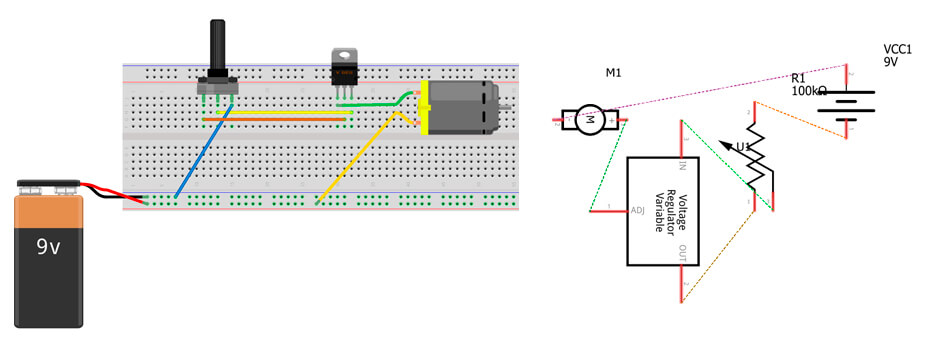
We did not have a clear or precise image of what type of transistor or if they had to which direction it had to be oriented, but like everything with trial and error we could discover it. We have used a DC motor that we connect to a SC2625 transistor of which the first and second of the legs we connect to the potentiometer, the second of the transistor connections we connect to the motor and which we connect to ground to terminate the circuit with the battery.
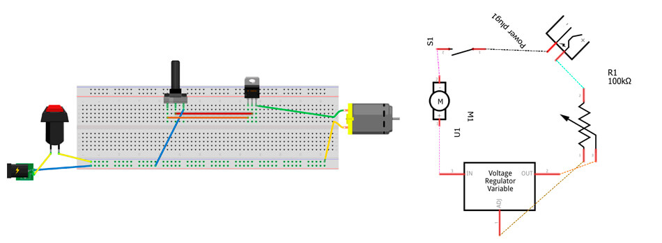
After seeing the circuit and the assembled machine, we could see what we wanted and what we did not want in the redesign of our new spinning machine. So we got down to work and created a brainstorming where the main change is to eliminate the battery by electrical current, for this we use a transformer that we place at 9 volts as the battery since we knew that it was the power received by the motor. other changes were to add an on / off button. but the rest of the circuit stayed the same since it worked perfectly for what we needed.
After approving the changes and everyone being in agree, we got down to work and replaced the elements that we wanted to change in the breadboard, everything worked at the first time so the circuit was ready to passed to the next part of the group that was in charge of making the files in rhino and could integrate the circuit in the design.
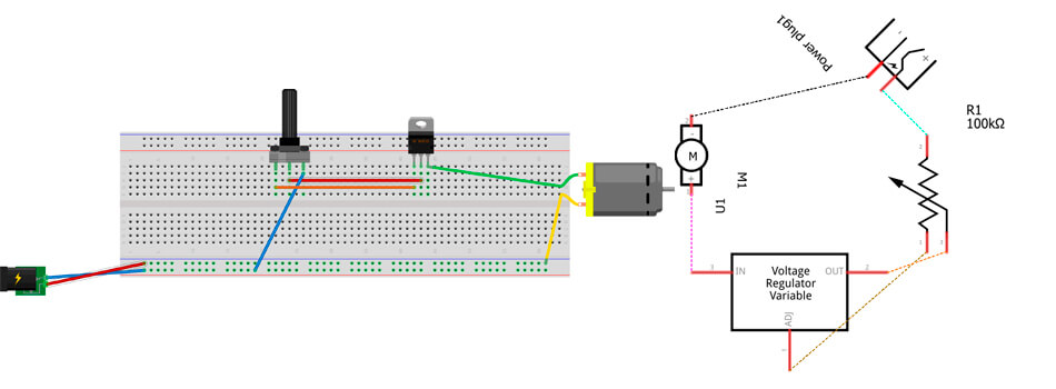
When we placed the circuit in the model in rhino we realized that the on and off button was not necessary so we already eliminated the button so we would only be left with the following elements: DC motor, SC2625 transistor, a potentiometer, all this coupled with a DCpower supply.
URSULA, Spinning Machine 4.0
Brainstorming
Building the machine was frustrating for the team, as we had several pieces (for more than one machine) and each for a different version. So everything was mixed and we took longer because of this.
But after getting it assembled (finally) we decided to do a brainstorming in order to put in common the ideas of our new version of the spinning machine. We divided this brainstorming by 4 fields: design of the product, user experience, electronics and other tools or machines that could be linked. We took about 10 minutes of thinking out loud improvements.
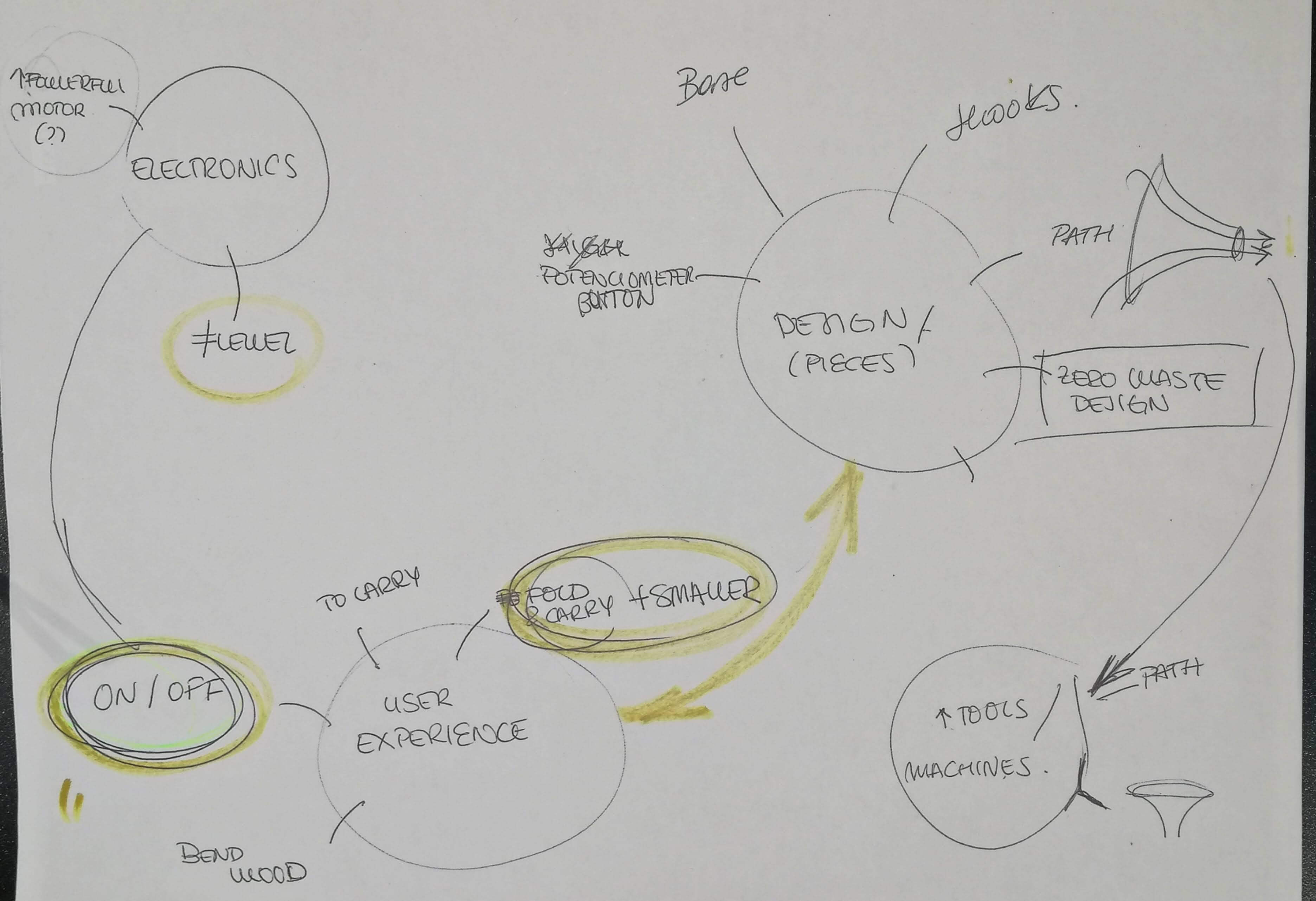
Based on our stressful situation on building it up, there were a lot of ideas in the user experience field and design. After gathering about 15 ideas, we selected 5 of them so it could be an approachable project. In the electronics we decided that there was a need to turn the circuit on easier, and not connect it to the battery directly.
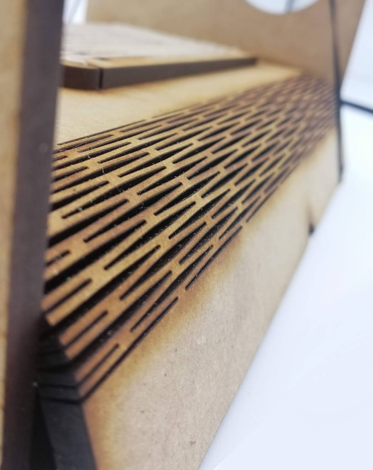
At the User Experience we decided to try to make it as a transportable machine, easy to carry; and a little smaller. For the design improvement, we saw the necessity of reducing the waste and the material used, as there we analized that there were several components that weren’t that important in size. However more changes were included during the design process as we saw the opportunity. For example we included a mini loom in the base of the machine and a user manual (how to build it after cutting and how to use it) to make the Open Source file more complete.
After defining which path we were going to take as a group, we divided the work by teams: Edu for electronics, Marisa and Olatz for documentation and creating a manual; and Arantza and Elsa for the design of the new machine. As a group work, every task was linked to the others so communication was crucial to make it work.
Design - Rhinoceros
After deciding what improvements we would make, it was time to design. We used Catherine Euale’s files to use the same measurements and make sure it would work. From that point, we made changes.
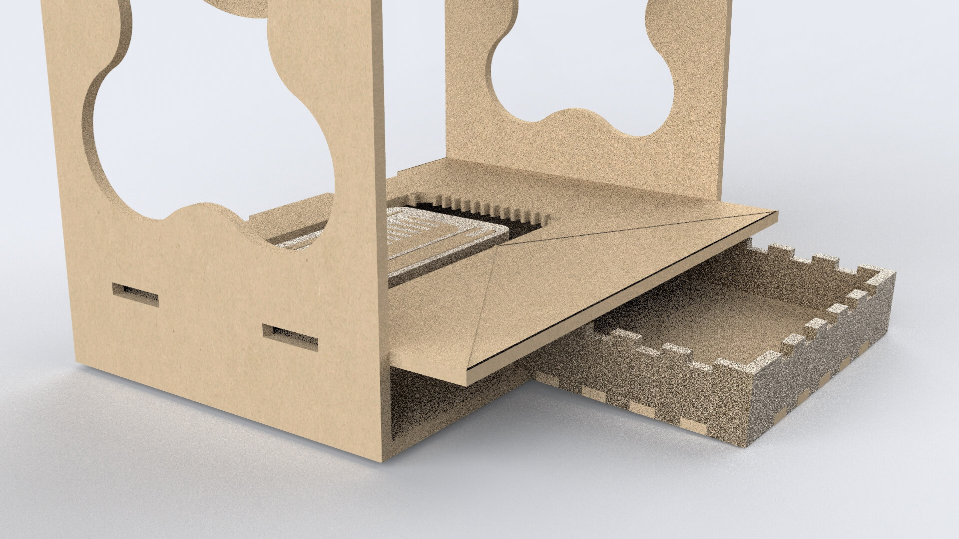
Base
We wanted one of the sides to be able to be opened up to see the inside of the machine. We used Boxes.py website which generates the box that you want.
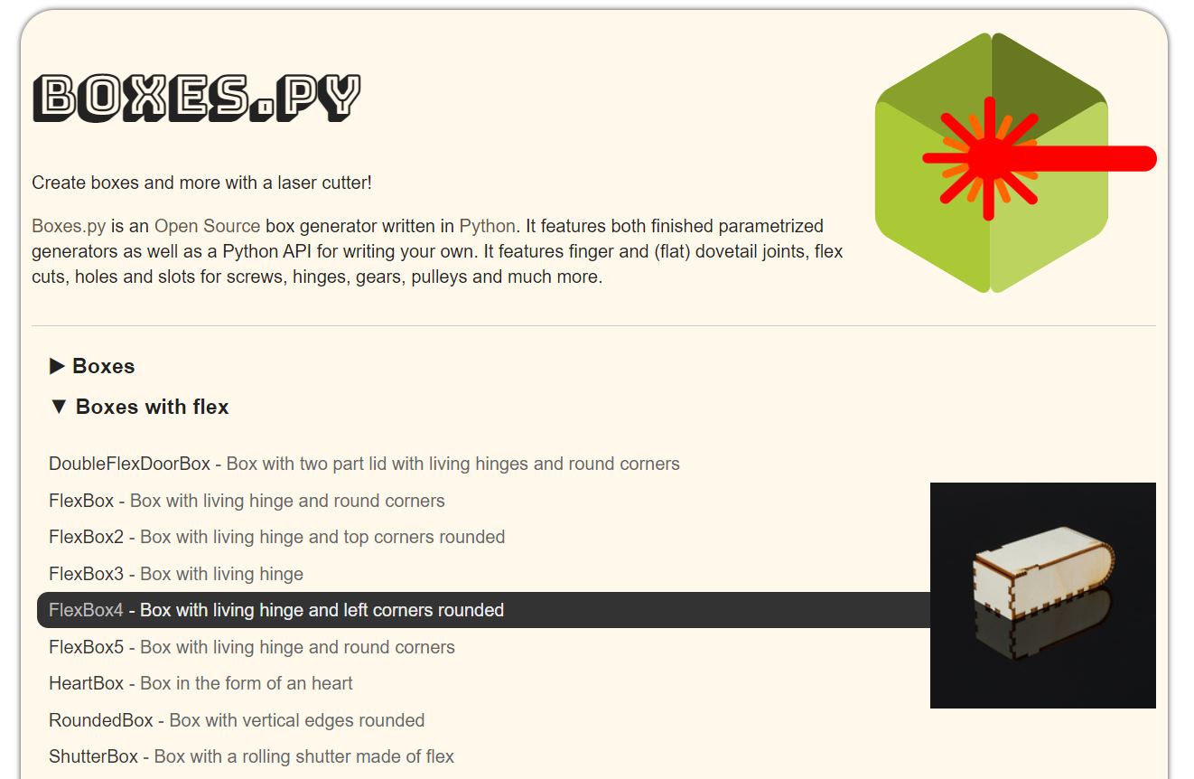
It has different shapes and types of box options. The plans it generates are for laser cutting because it has tabs that are used to fit the pieces.
One of the corners had to be “flexible” to open and close the machine. So, once you have entered the parameters, the box is generated with a parametric design to obtain that freedom of movement and you only have to download the file
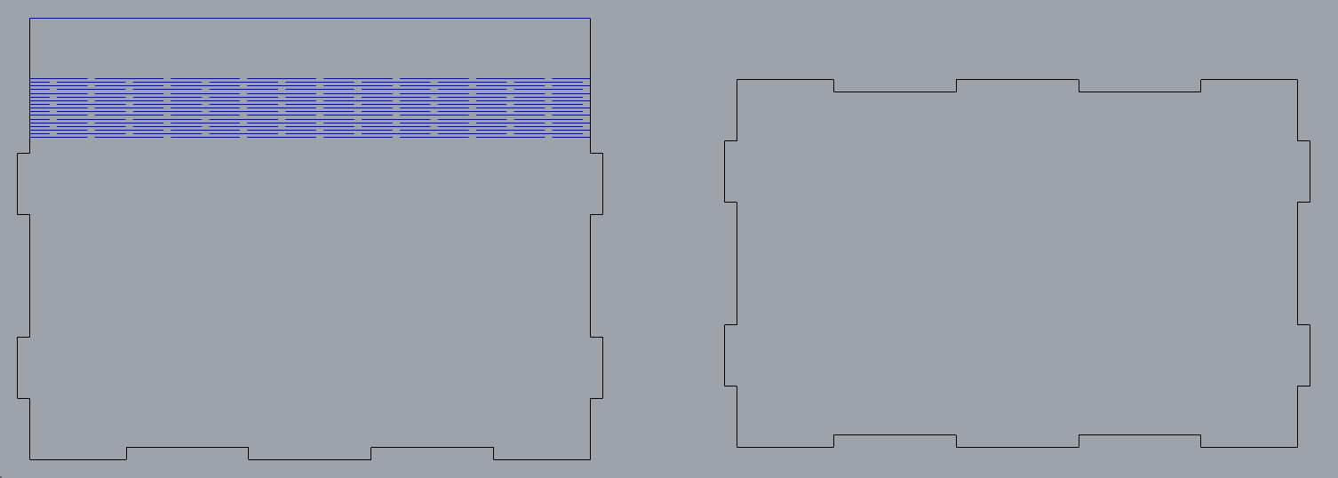
We made some changes to that file. The box had 2 curved corners, but we wanted one. We combined it with the original file and got the plans of the box we wanted. Moreover, we reduced the height of the base, in order to save material (instead of 6 cm of height, it had 3 cm).
Gear
We put the gears on the surface of the structure to have more space for other components. They had a circular shape, which complicated their distribution so as not to generate material waste and without affecting the structure of the machine.
As a result, we put 3 of them on each side of the structure and the other one inside the circle that would serve as the lathe structure. There would be waste of material, however we used it as another tool (you will see how Marisa uses it).
Moreover, we scaled the diameter of 4 of them, because we noticed that they were just a stopper. The other ones were more “important”, I mean, they were connected to the motor with a rubber band, so if you change the diameter, it will affect the speed. We decided to leave as the original one, just in case.
We maintain the diameter of the holes that are in the gear. We used the same tubes as in the Speed machine 3.0.
Structure of the lathe
We started placing the pieces to optimise the space. We started to place the pieces in order to optimise the space. We saw that the long pieces of the lathe could fit between the pieces of the structure if we reduced their width.
So we reduced it because it didn't affect the operation and it was to our advantage to do so. Instead of having 3 tabs, it would have 2 because they would be too thin and they could break easily.
Holes
We added some holes to be able to regulate the speed with the potentiometer and another one to pass the power supply cable through.
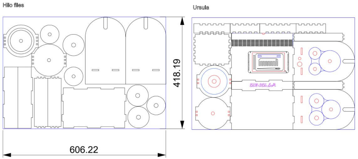
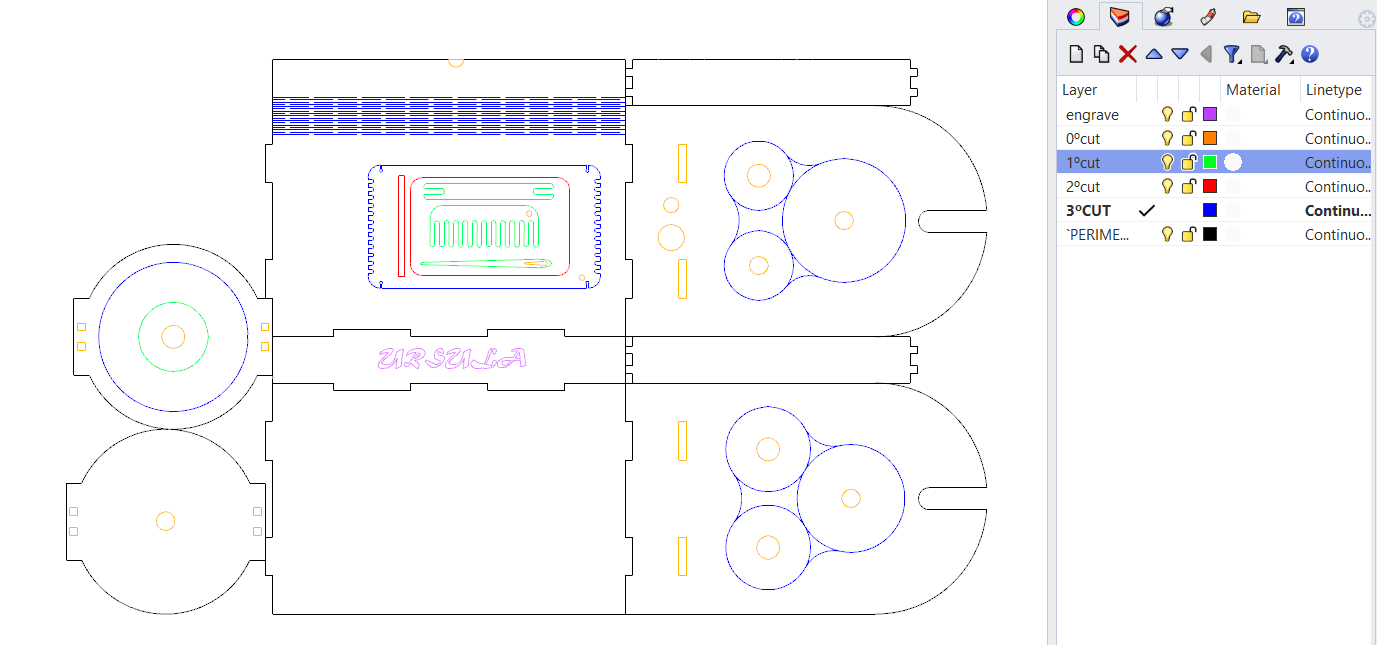
Distribution
This was the distribution to save material. It is true that we managed to save a little bit, however, we made a 2x1 machine: an hilo spinning machine and a mini loom, plus we added a small box to store tools.
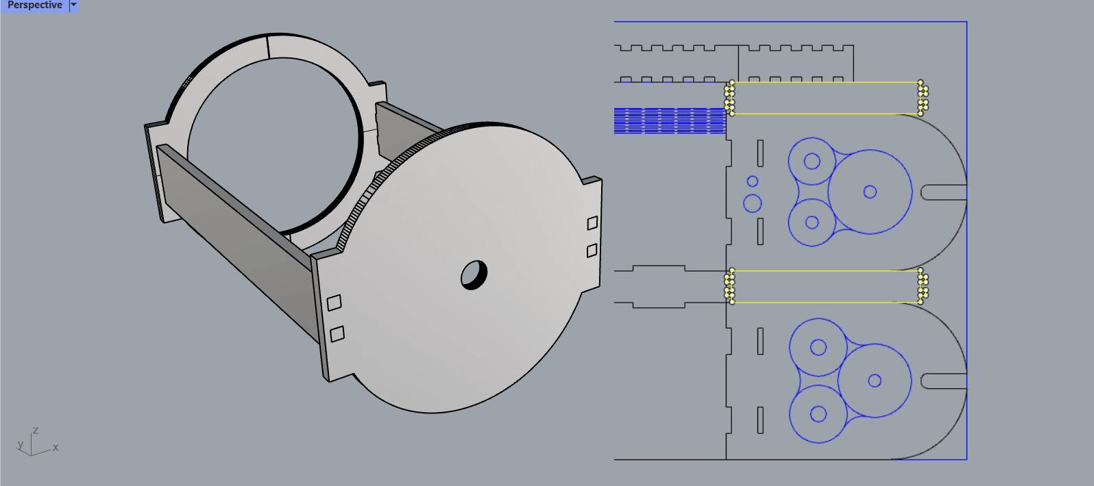
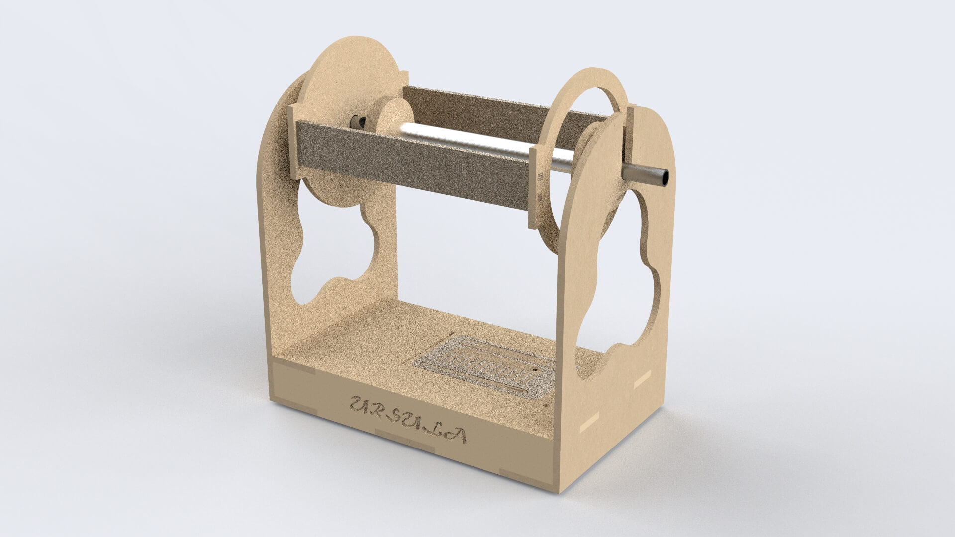
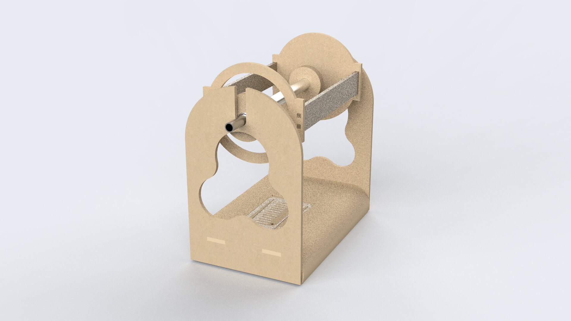
Ursula 3D
This would be a first view of the spinning machine:
Building Ursula
Laser cutting
As we learned in the assaigment of digital bodies, the cutting order is very important.
We used these parameters:

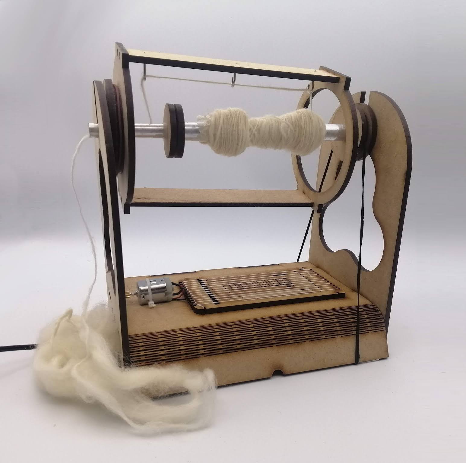
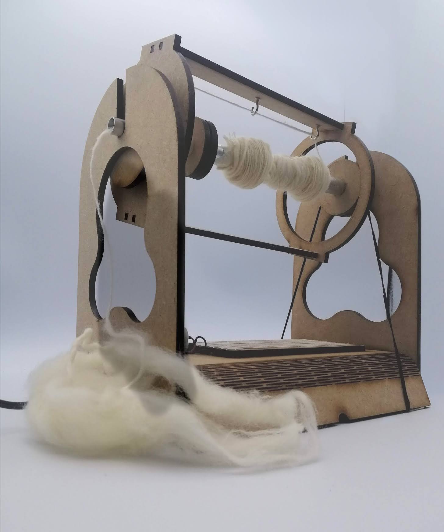
Ursula's birth
Here is a summary of how Ursula was born:
And here is how it works:
Other tools
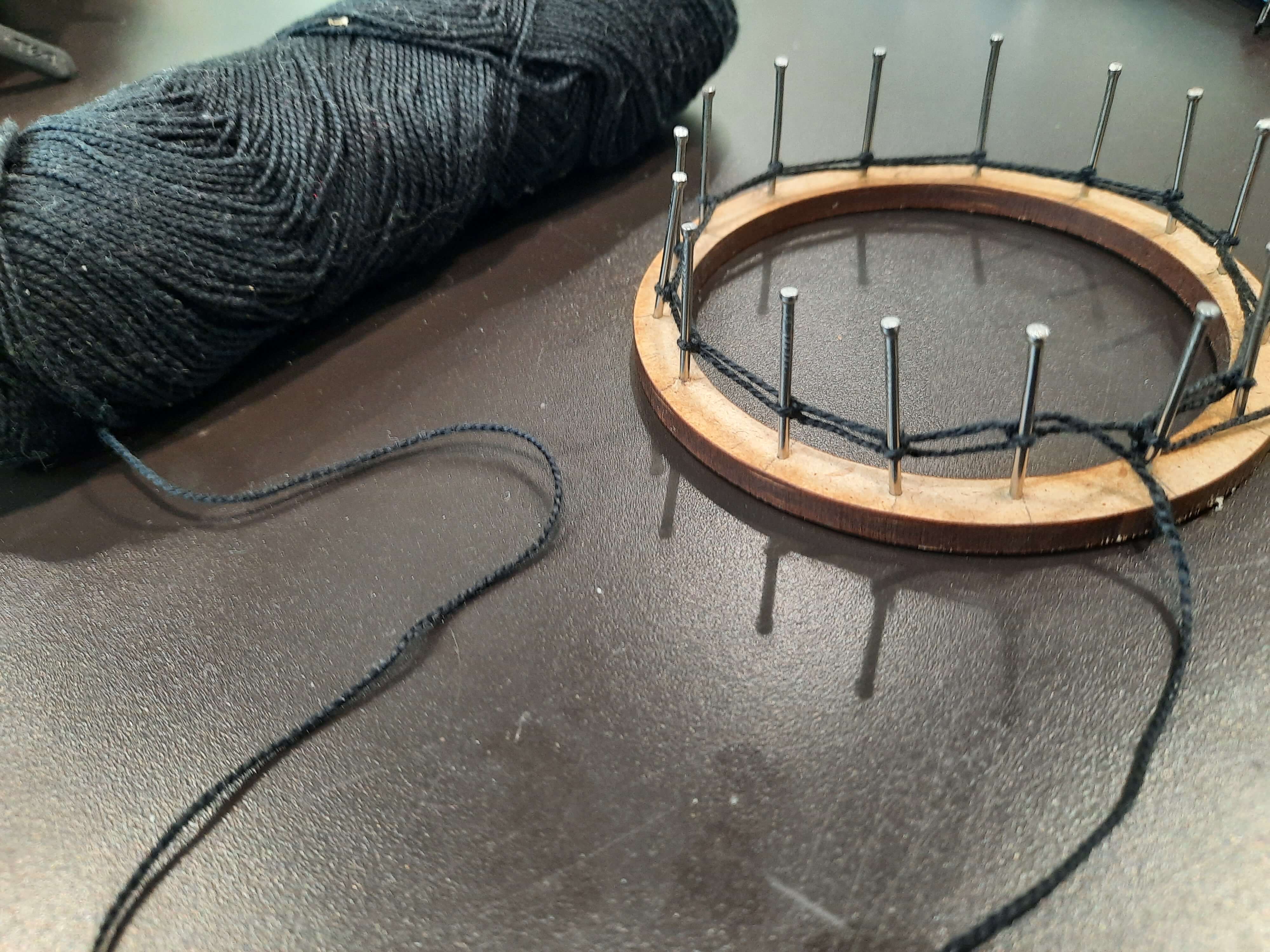
Marisa’s loom: As I mentioned before, with the wastes, she did a circular loom. She just hammered in a few nails and the loom was done.
Manual
We thought that it would be great to have a manual to build your own spinning machine. Olatz made this amazing user manual to make your life easier if you want to build it.
Download links
- Ursula 3D: