02 | DIGITAL BODIES
This week's aim is to learn how to make a 3D scan and use 3D programs like Makehuman. Furthermore, we learn how to manipulate a 3D mesh in Rhino and Slicer and translate it into 2D plans that can be laser cut and assembled.
RESEARCH | IDEATION
For the DIGITAL BODIES project was inspired by artists working with deforming the human body by working with negative and positive pace, or by changing the body's materiality, while keeping its defining characteristics. It is very interesting how little of the body we need to see in order to identify it as a body.
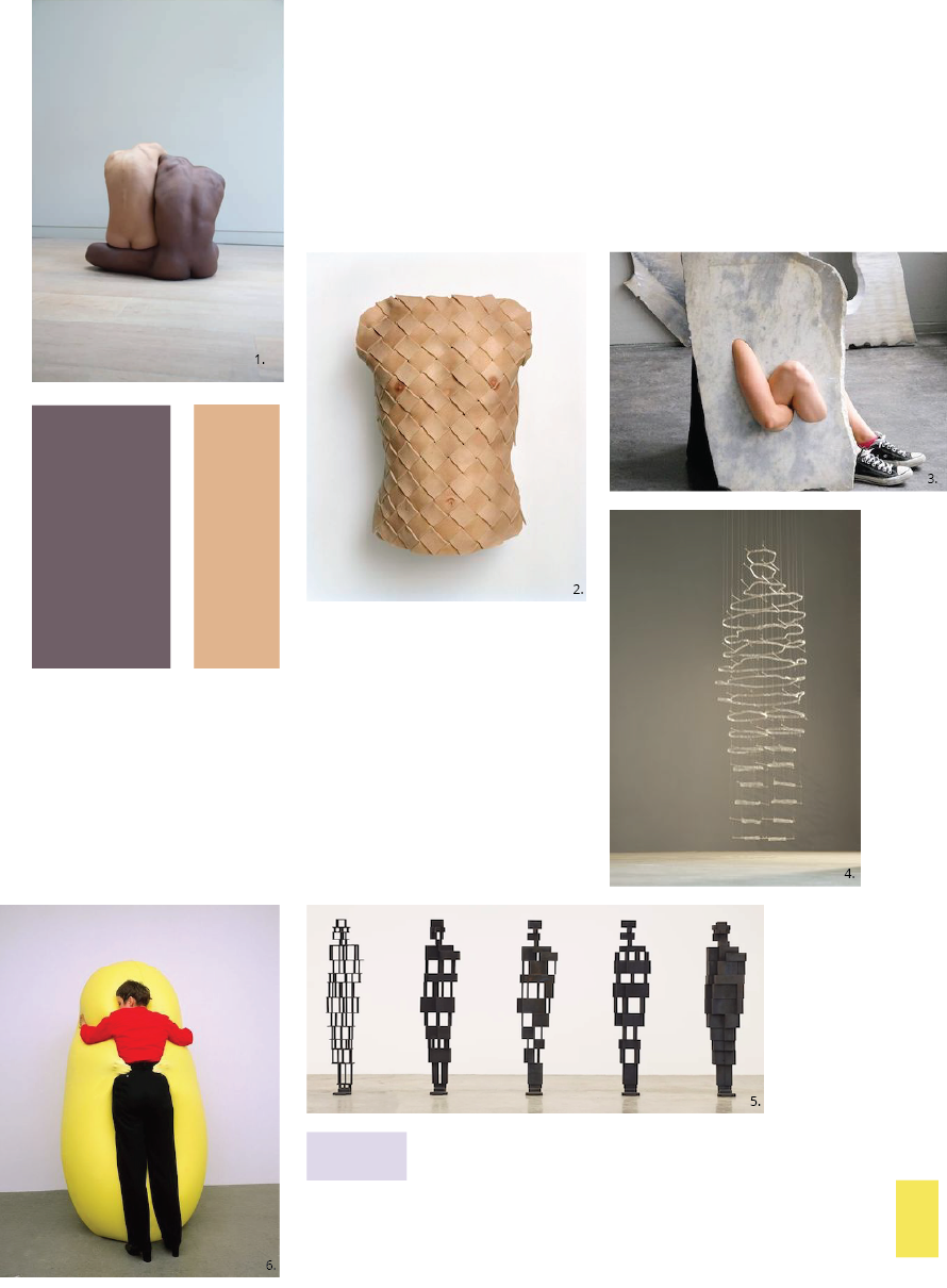
- 01| FUNTION, 2018, by CHLOE ROSSER
- 02| CUIRASS, 2005, by ANDERS KRISAR
- 03| FLEETING PARTS, 2016, byMILENA NAEF
- 04| FIRST IMPRESSION, 2010, by ÆSA BJÖRK THORSTEINSDÓTTIR
- 05| OPEN BLOCKWORKS, 2014-22, by ANTHONY GORMLEY
- 06| YELLOW SCULPTIRE, 1998, by nHANS HEMMERT
PROCESS | WORKFLOW
This week we have focussed on learning the different digital platforms and tools for working in 3D on the computer. Furthermore, we have been introduced to the 3D scanner and the laser cutter and thereby learning tools to transfer the real world into the digital and vice versa. As this is my first time working with most of these tools and platforms, this week has been a lot about getting to know them, not being scared of making mistakes and sitting 1 hour just trying to flip a figure in Rhino. Our instructor Louise Massacier has been an amazing help with this, as she has gone through the tutorials of Rhino with us so we could test the exercises shown there. As it is a very complex programme to be introduced to.
TOOLS
TURORIALS
GOOD TO KNOW | 3D SCAN
One of the first things we got to do was testing 3D scanning our bodies at the FabLab in Sauðárkrókur. We used the Revopoint Pop 2 scanner. This was harder than expected, as I like to show movement in my work I chose a pose that hinted movement. This however was very hard for the scanner to scan, so apart from sore knees, I ended up with a scan that had A LOT of movement in it, to the point where it is hard to see that it is a body. However, as showed by my various references, very little is needed to show the human characteristics of a figure. So in that sense I got to experience my body deforming while still being identifiable as a body. Unfortunately the obj and ply filer could not be opened in Rhino so I had to download MESHLAB to open the file.
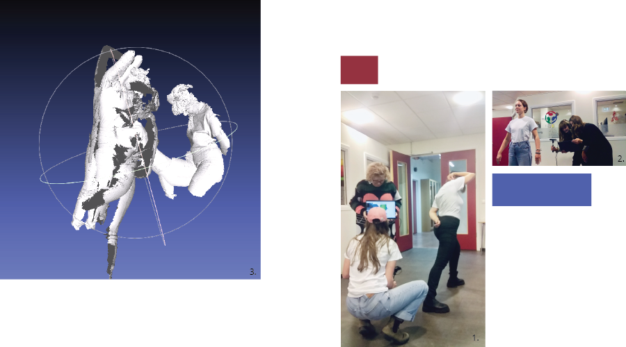
01|         Scanning my movement pose.

02|         Scanning Alice's still pose

03|         File opened in MeshLab.
GOOD TO KNOW | MAKEHUMAN
MakeHuman is an old 3D program where you can manipulate already-exciting-3D-figures, by altering their body shapes, gender or poses. These files can be exported and importet into programs like Rhino, where they can be further manipulated.
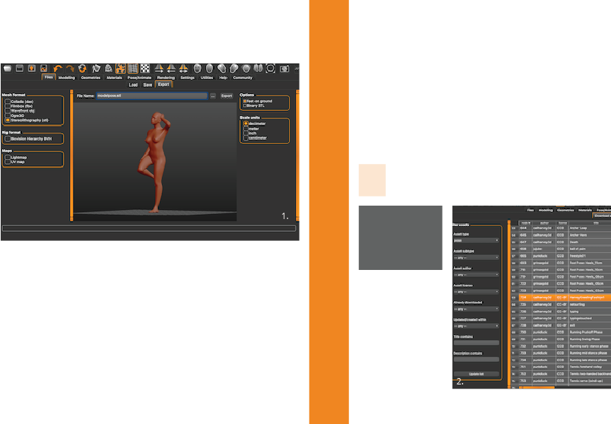
This program is fairly easy to navigate, though it is quite old and sometimes it crahes. Here are the steps I used:
01|         New pose: Go to Community, press Synchronize down right, choose the pose and press Download.

02|         Save: enter NAME and WHERE to save it, save in .mhm

03|         Export: enter NAME and WHERE, save in .stl or .obj
GOOD TO KNOW | RHINO
Rhino is a 3D programme that is used by designers and architects to make 3D models and blueprints. It is a fairly complex programme, based on writing in a command. Obs, the interface between PC and Mac differs, so do not be confused if it looks different on the tutors screen. Rhino has a lot of possibilities and various ways of working with it. For this week we used it to manipulate the human body as a mesh. My idea was to deform the body by adding shape to it, but then I was introduced to the capping function and thought of the idea of removing parts of the body, altering it by the use of negative space. Therefore I tried removing parts of the body using other functions than just the poly line. The circles I ended up with cannot however be caped (closing the mesh) therefore I had to use an extrusion of the cutting shape and use the command meshbooliniandifference.
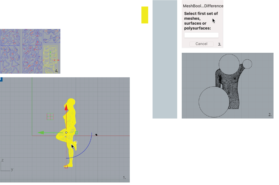
01|         Rotate you use the Gumbal functioin that will give you the arrows to flip it over.
            Scale you write in the command bar: Scale (enter) place one point at each end of the body
            you want to scaele, then drag the line to make it larger or smaler.

02|         Cut the body: Circle or plyline tool, command: splitmesh (enter) select body (enter)
            select cutting line (enter)

03|         Closing the cut for a straight polyline: command: cap (enter) select body (enter)
            Closing the cut of a curved line:
            01| Extrude the curved line to become a surface: command: extrude (enter) select
            line and drag it out. Place the shape to the open mesh.
            02|  Close the mesh: command: meshbooliniandifference (enter), select body (enter),
            select extrusion (enter).

04|         Export the mesh model as a stl or obj, I use stl. In order to open the file in Slicer.

05|         Post work in Slicer. Plans from slicer: when they are imported check:  all pages, preserve units (mm),
            Doublechek distance: command: dictance (enter)
            Export files: Files, Export selection, Name, Place, .pdf (enter). Choose dimensions,
            display colours, view and output scale: set..., select the area to be exported (enter), apply.
GOOD TO KNOW | SLICER
Slicer is another open-source program that helps sliceing the rhino 3D file into 2D blueprints, that can be read by the laser cutter. The program is easy to navigate by using the toolbar on the left-hand side. My nesting files and 3dmk can be found here 34.
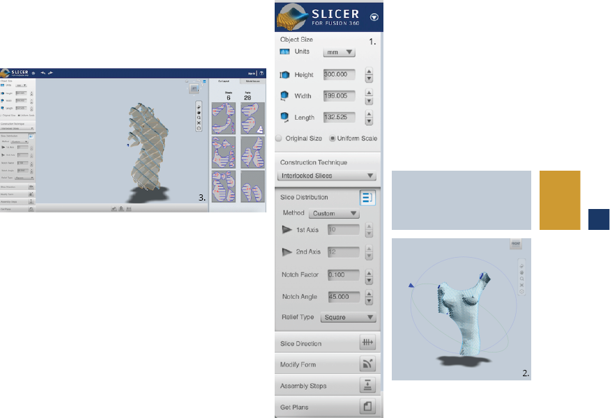
01|     Menue bar: here you have almost all the different settings

02|     Stacked slices, by going into slice direction you can manipulate the slice direction, obs that
        to change it you have to be perpendicular to the streering circles.

03|     Interlocked slices, obs that when they turn red ion your plan pannel they are too large for the
        sheet and when it is blue it is not connected to another piece. This can be changed by either
        altering the size of the model, changeing the dimentions of the sheets or moving the piceses
        manually, here you also have to be perpendicular to them to move them around.

04|     Save the nested file as a 3dmk, then export the nesting as an stl or obj (I used stl).
GOOD TO KNOW | LASERCUTTER
Finally it is time to bring the digital world into the real one. This is done by all the aforementioned programs and tools. to end up with plans for the laser cutter, the local one is an Epilog. I wanted to try the different slicing models so I made two small bodies instead of one large one. I cut out a stacked slice model and an interlocked slices model. The cardboard used for cutting is a 3mm one. After assembling the models I wanted to highlight the cut-out circles by extending the body with circles. At first I just wanted to cut out simple circles, but then I was inspired by my peers to use kerf patterns to make the cardboard bendable 2. Unfortunately the settings for the cutting went wrong so it did not cut through, but even that made the cardboard more bendable.
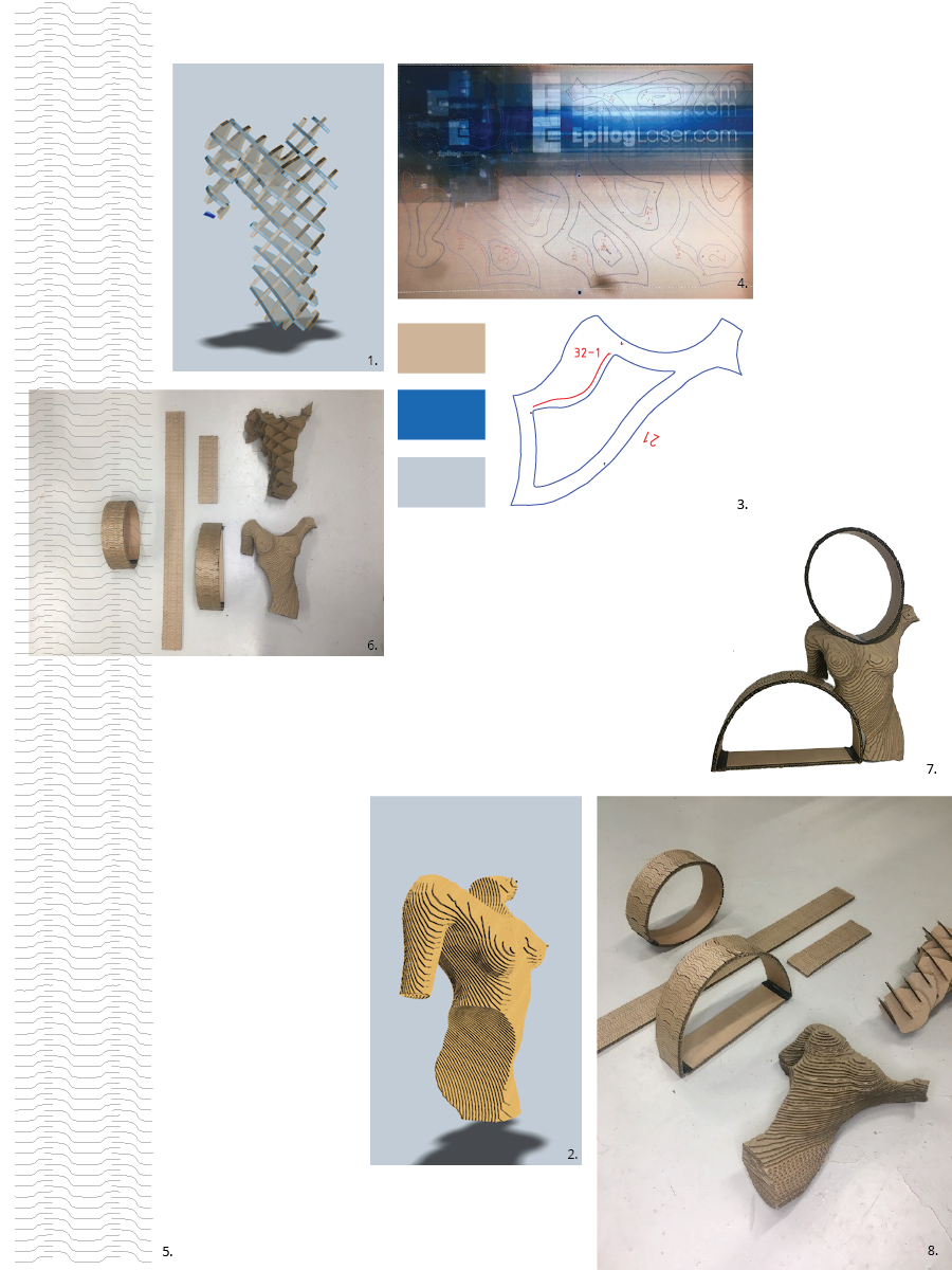
01|         Intelocked slices model in Slicer.

02|         Stackesd slices model in Slicer.

03|         Blueprint of one slice from 02| that are read into the laser cutter, the blue colour is
            cut and the read is eching.

04|         The laser cutting in action.
            Settings for 3mm
            Auto focus: Thickness
            Thickness: 3mm
            Cut/eching (both vectorise):
            Speed: 60/100
            Power: 40/20
            Freq: 10/10

            Settings for 8mm
            Auto focus: Thickness
            Thickness: 8mm
            Cut:
            Speed: 40
            Power: 60
            Freq: 10

05|         The Kerf model made in illustator, imported as a png and expanded as line art.
            The pattern was copied and lined up by using the coommands: command, c, f, d.

06|         Laser cut models.

07|         The circles and model assembled

08|         Laser cut models.
The kerf pattern 1 was obtained..
The laser cut nesting 2 was created using..
Fabrication files
-
File: KERF PATTERN ↩
-
File: LASER CUT FILES ↩↩
-
File: NESTING FOR MANIQUIN ↩
-
File: Slicer file ↩