03 | CIRCULAR OPENSOURCE FASHION
The aim of this week is to create a garment with modular elemtns/structures/connections/tesselations that allows the used to change the shape of the garment or resize it.
RESEARCH | IDEATION
My interest for this week was to look at how the use of the modularity can enter the threedimensional space by the angle of interlocking. The focus was to experiment with creating threedimentional and haptic surfaces that through their structure suggest movement, i.e. wearing. Furthermore I wanted to create a zero-waste pattern in order to minize the material off-cut. This proces was initiated by looking at the logic behind interlocking and modular surfaces, a some good guides for this are Freeform Origami Tesselations by Generalizing Resch's Patterns by TOMOHIRO TACHI or E. S. HUR's Transformative Modular Textile Design. These researches show how to work with simple geometric shapes to create complex patterns and surefaces. One of the most interesting aspects of E. S. HUR's research was the experimentation with incerasing or decreasing size in the pattern by working out of the same base, an aspect which could be introduced in the threedimensional field as well, by increasing or decreasing height. I also made some extensive research into different base patterns within modular surfaces, here I looked at designers sucha as RONAN AND ERWAN BOUROULLEC and MATIJA COP who both works with three dimensionality in their surfaces, MATIJA COP also works with de- and incereasing the size of the structure. I was very inspired by KSENIA SZYBIST's Architecture of Lines N.2 whcih is a threedimensional modular sureface made form cut plastic sheets. This piece is however not zero-waste, nor is it interlocking as it is glued and sown tohether. So based on the aesthetics of this surface I ventured out to find a way of making it zerowaste and interlocking. I also wanted to attempt to grenerate the pattern to a seaweed material I had made previously this year. Its selfsupportive qualituies eludes to that of soft plastics or leather, and its translicensy and organic colour variation is an interesting aspects when working with overlaping surfaces, and aspect which remined me a lot of LOUISE MASSACRIER's work from this course.
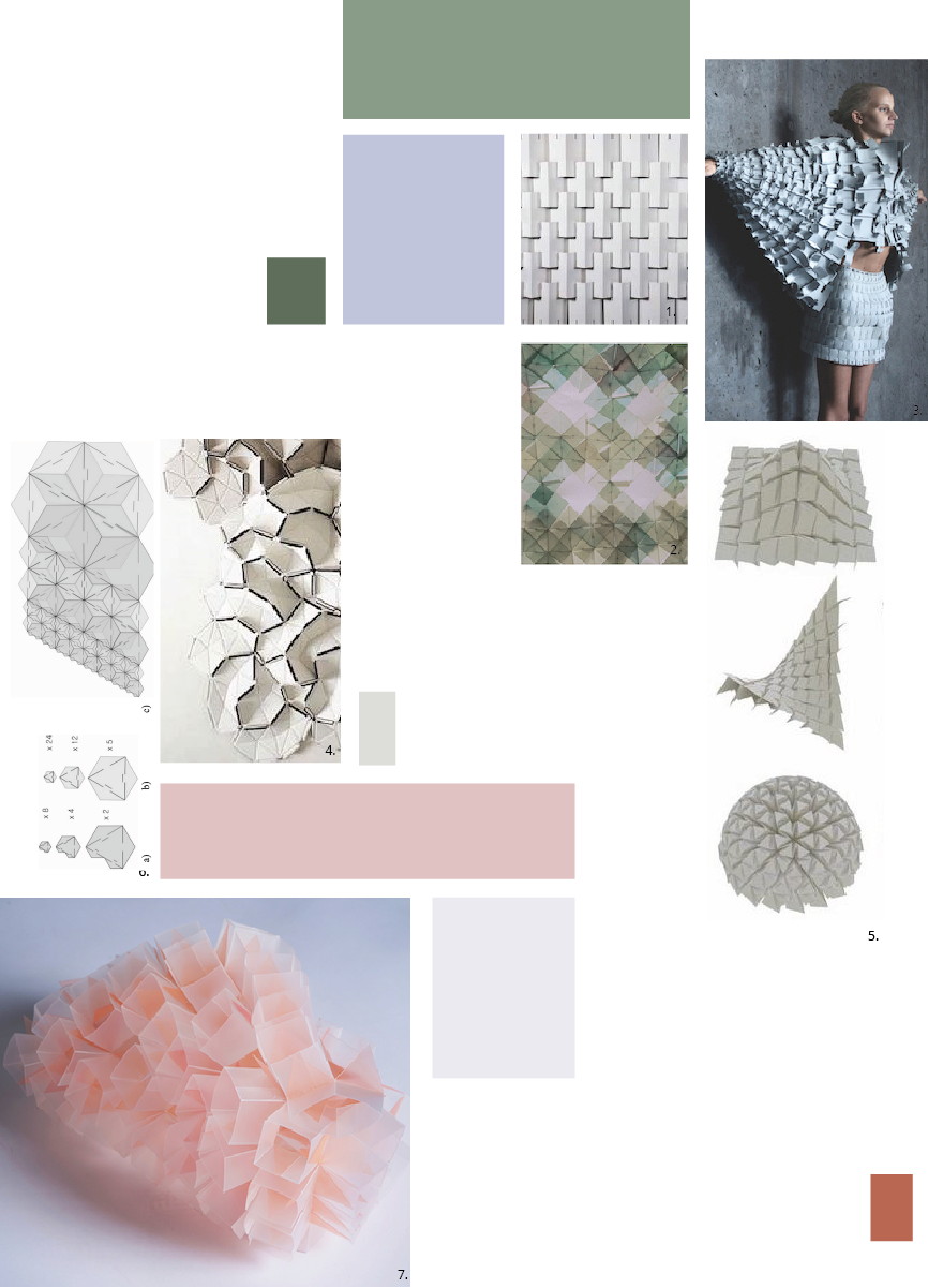
- 01| 3D MODULAR SURFACE, NA, by NA
- 02| CIRCULAR FASHION, 2021, by LOUISE MASSACRIER
- 03| OBJECT 12-1, 2013, by MATIJA COP
- 04| CLOUD, 2009, by RONAN AND ERWAN BOUROULLEC
- 05| FREEFORM ORIGAMI TESSELLATIONS BY GENERALIZING RESCH’S PATTERNS, 2013, by TOMOHIRO TACHI
- 06| MODEL FOR INCREASING SIZE IN MODULAR PATTERN, 2011, by E. S. HUR
- 07| ARCHITECTURE OF LINES N.2, 2018, by KSENIA SZYBIST
PROCESS | WORKFLOW
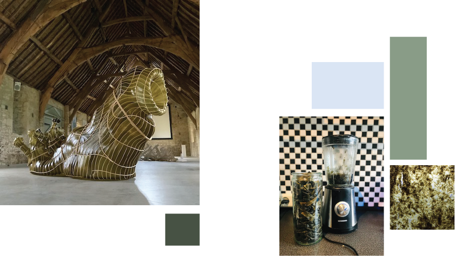
This week has evoled a lot around working interchangeably between Rhino, Illustrator, paper and the laser cutter. My concept was to create a modular surface that goes into the threedimensional space by interlocking multiple modules at different angels. My aim was to use a seaweed material I created from the waste of the seaweed installation KOMBU NUDIBRANCH created for Julia Lohmann in 2022.
GOOD TO KNOW | SKETCHES
I started the process by wrapping my mind around the logic behind modular patterns and the interlocking. This i did by cutting in gridded paper, making small samples. The grid system is really good to align the shapes and the cuts, especially if you create a diagonal grid too. I quickly went into how it is possible to fold and interlock the modules to create threedimensional shapes. After making the samples I started working on the modules in seaweed
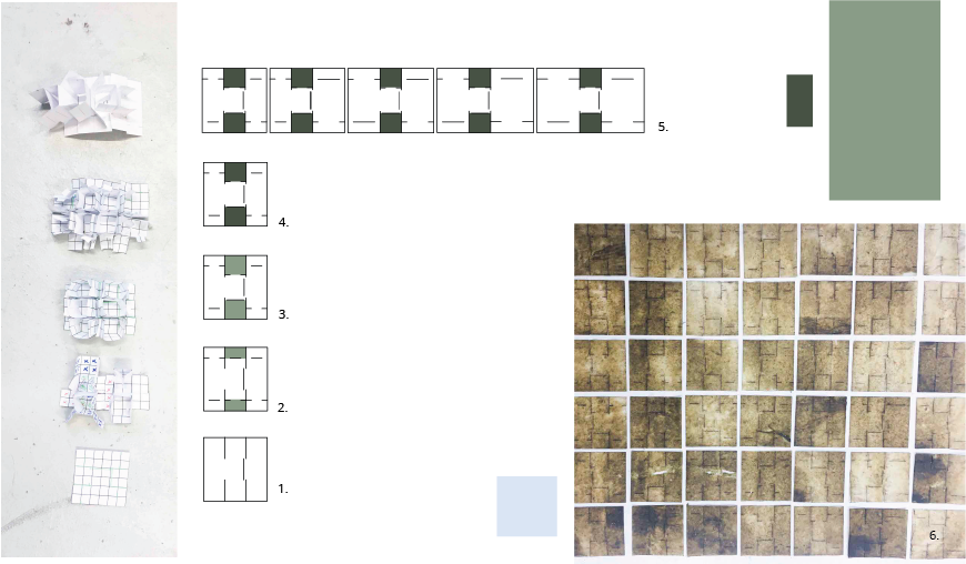
01| First sketch and paper model of the square mnodule.

02| Second sketch and paper model of the square mnodule assembled with one squares distance,
the interlockings marked by the colour.

03| Third attempt, trying to get the 3D squares tightly fit in the rows, by making new cuts,
shown by the coloured parts.

04| Fourth attempt, trying to get the interlocking squares between the rows away from the top
surface. This was solved by simply changeing the direction of the interlocking squares, putting
them on the back of the surface. Shown by the alteration in colour.
by the dark

05| The fifth attempt was trying to see how the alteration of size would work, keeping the
shape of the rectangle to keep the prpeat without waste.

06| First attempt on cutting the modules in the seaweed. Here I tried different lenghts of the
cuts inside the model, to try the tear strength og the seaweed material.
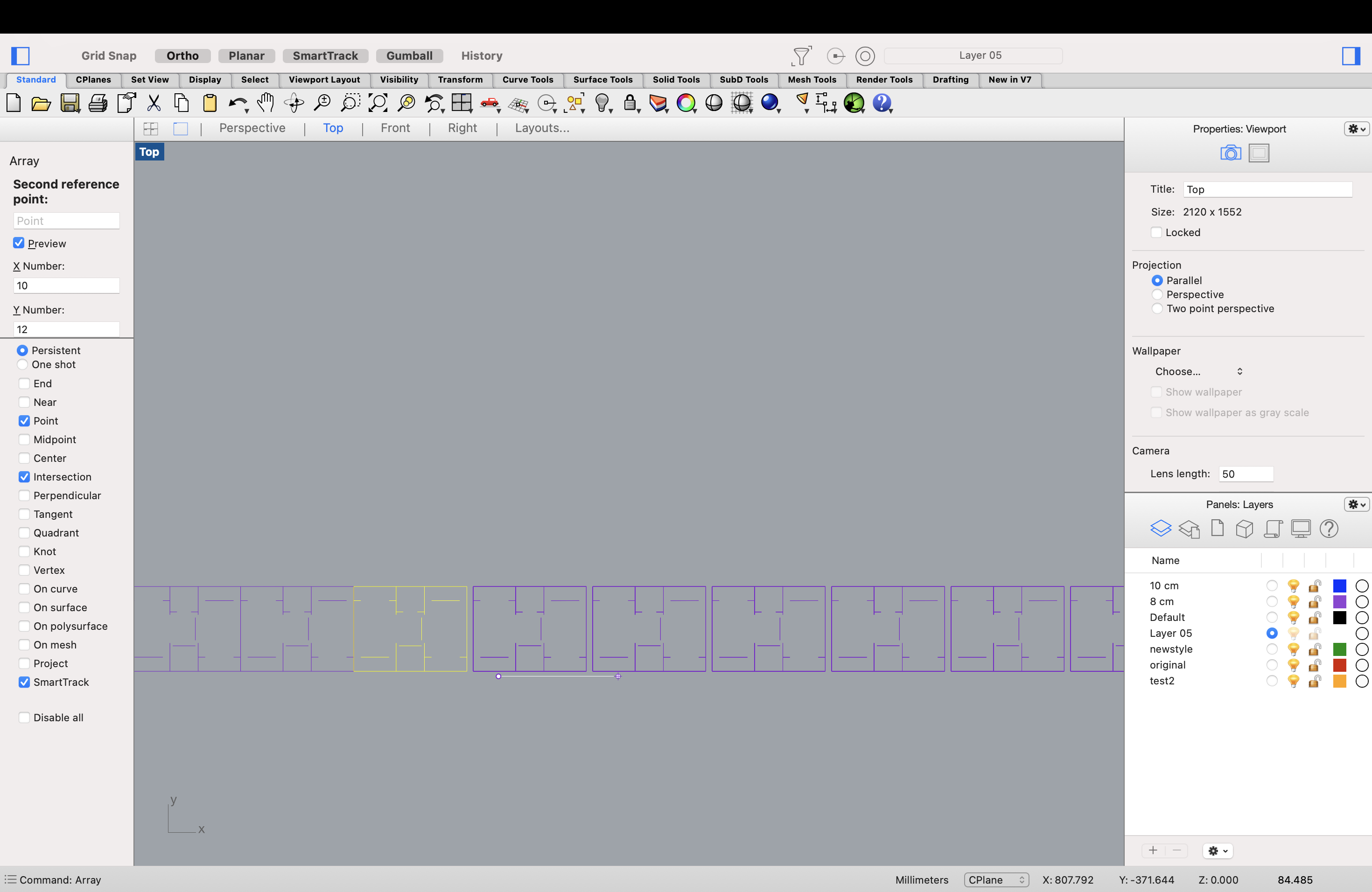
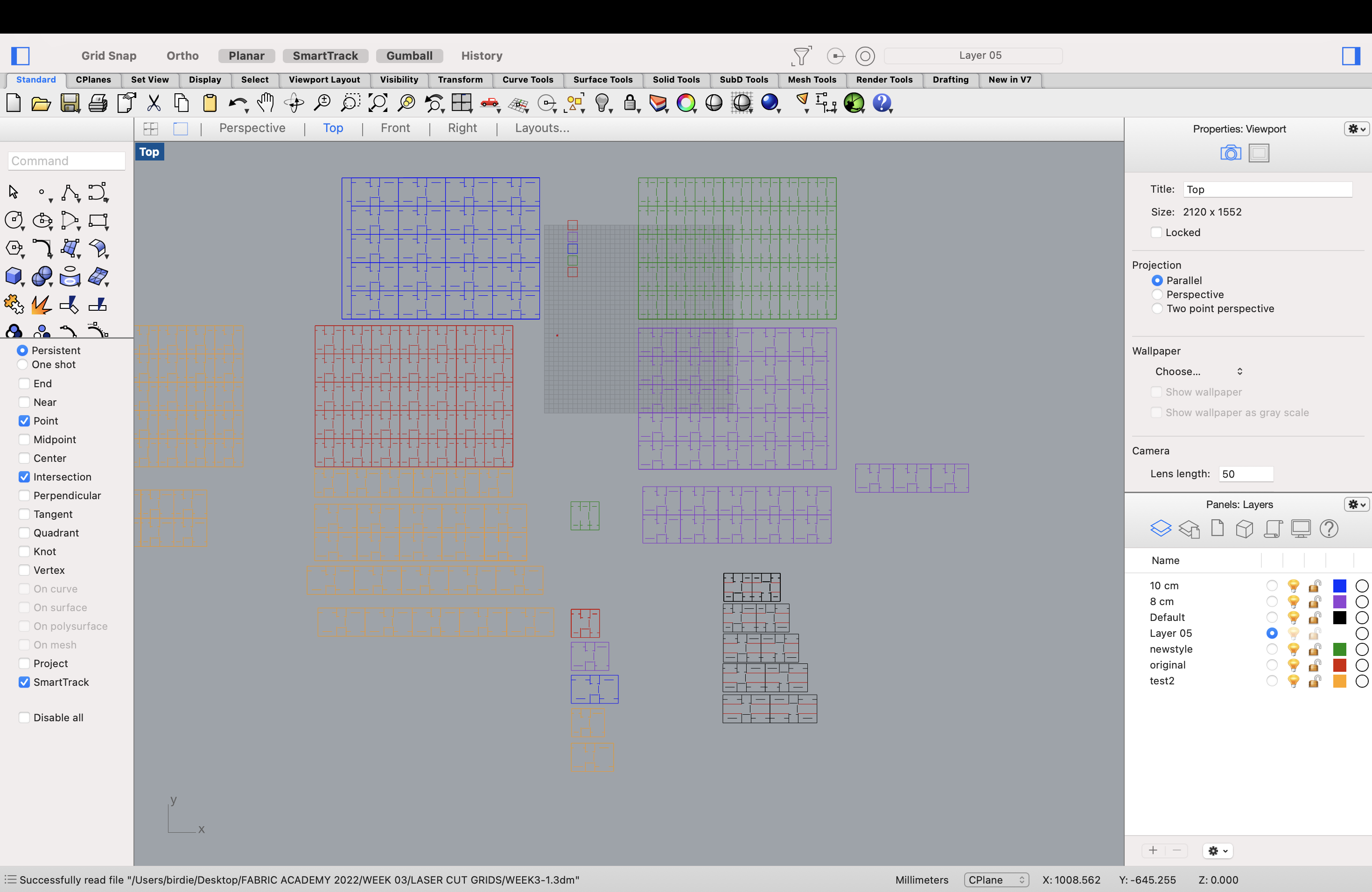
GOOD TO KNOW | RHINO
Rhino was during this week to gennerate the pattern array, using the commands described below. However the issue with this tool is that it will create a double line of cutting in the laser cutter. I have not found a solution for this as of yet. In order to export the models to pdf for the laser cutter I used export selection, and manually set the window. Important here is to make sure that all of the exportations are in the same scale. This I solved by using a standard size of 500mmx300mm and putting this around the same selection and then putting it around my selection. I tryed without this process, and the size difference will be in the lasercutter file. This can be rectifyed by changeing the size in the laser cutter display programme.
01|     Command (array), select object to array (enter), give amount of copying in x,y,z direction (enter),
place it out (enter).

02|     Export selection,  make sure the scale is 1:1 so that the scale will be right wether you choose a small format or bigger.
Finally I also used rhino to make a digital display, I have not finished the sleve yet so the final rendering with specifics will come.
01| Make a rectangular surface, command rectangle: this wil beyour base plane.

02| Make the surface: make a square on top of the base plane, make a smaller square within.

03| Array the squares: use the array command make sure there is a distance between the the squares in the array.

04| Exreude 3 different sections in z plane, making the raise.

05| You now have the surface you want to extrude. Make this into a mesh.

06| Make the maniquin: Import stl file from make human.

07| Convert the meshes into quadmesh to make it less heavy, then convert to SubD.

08| Select a line on the sleeve, hold in shift command, doubble click the line you want to follow. Create a layer for this line. Dublicate the line by command: dubedge.

09| Cut the line to fit to the length you want.

10| Make a polyline

11| Divide curve in 3 segments: command divide.

12| Make surface: select points, click on the arrow on the points and extrude while holding shift. (extrude in x plane) Extrude in z plane by the same action just in the perspective view.

13| Project the segments you just extruded along the curve from the arm: use command flow.

14| Intersect the segments and the line, using command intersect.

15| Project each point to cplane as you work though each point : using command ptoject to cplane, be in the perspective view.

16| For each segment draw a curved polyline while being on the c plane for that point.

17| Make sleeve: command Sweep1: rail, Command: Rebuild to make more controll points.

18| Project the texture on the sleeve: command Flow Along Surface: select the corner of the texture and click where toy want this corner to be on the sleeve.
GOOD TO KNOW | ILLUSTRATIOR
I used illustratior to visually show how the final modules are assembled.
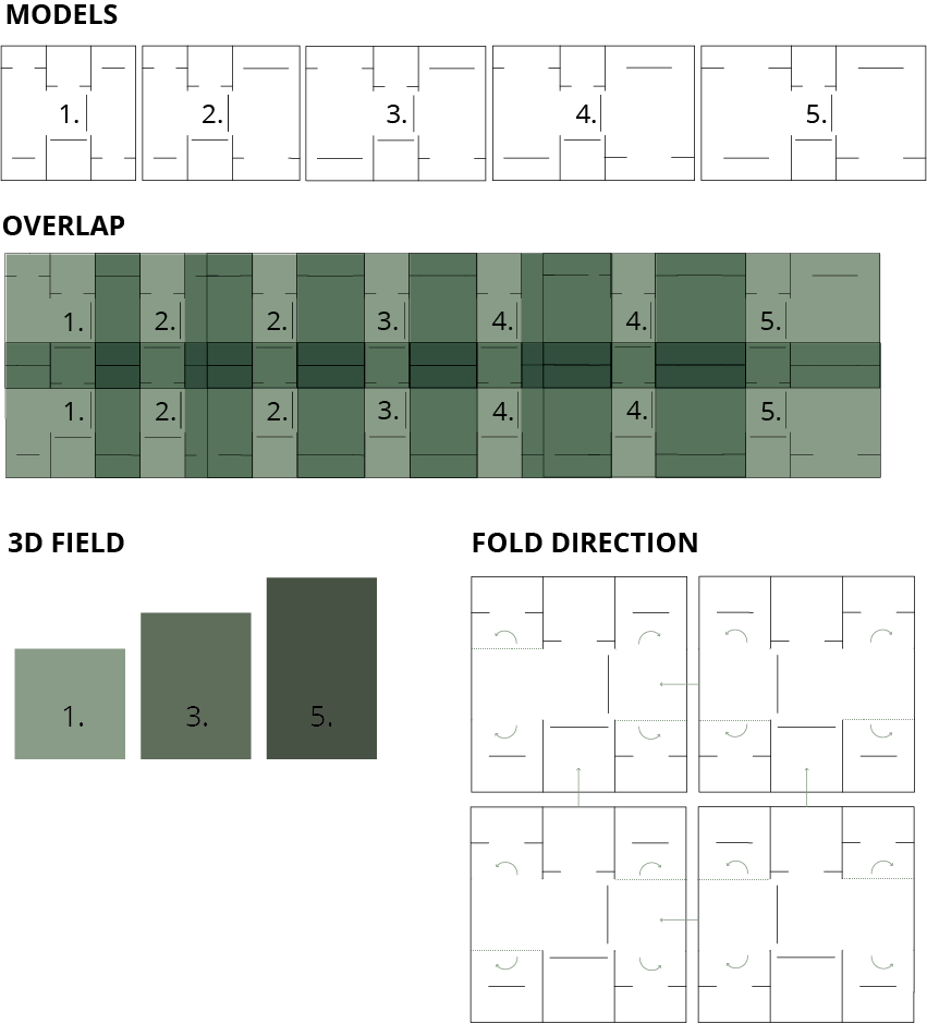
01| MODELS: These are the 5 shapes needed for a 3 step rise in the pattern, as the modules overlap
over 3 modules I creared two "inbetween" models that makes the transfere smooth.

02| OVERLAP: Here it is mapped oput how the modules should be places in order to overlap and interlock
properly in all directions.

03| 3D FIELD: the heights of the moduels.

04| FOLD DIRECTION: In order to get the square shape of the cube the material needd to be folded, and
when I finally assembled the final piece, I  realised that I could have eched the folds as the folds
are in the same side of the cuts. This idea is shown by this model, showing that the folds are folding
away from its center square.
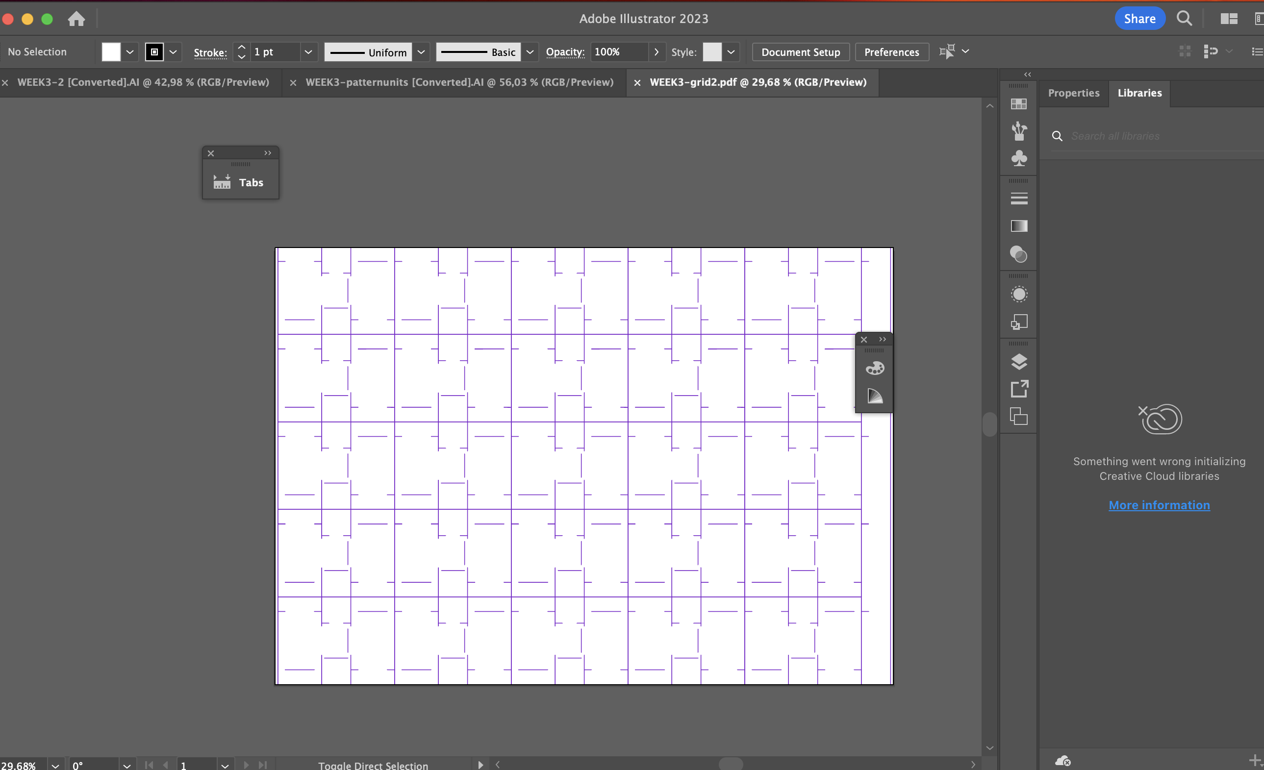
The laser cut modules unit patterns 1
The laser cut modules for one sequence 2
GOOD TO KNOW | LASER CUTTER
The laser cutter is an amazing tool and the Epilog we have here in Iceland is wonderful, as it allows you to use a camera to see the pattern on the material you are to cut, you can also copy/paste the pattern unit. This is very usefull if you are working with a ornaic shape, as I am, therby it is possible to optimise the use of the material. Furthermore is it possible to change the settings directly in the maschine, which is also a usefull setting. I started the lasercutting process by finding the right settings for the composite seaweed material I was to cut. This material is only made of seaweed and less than 10% glycerol which allows it to be cut in the laser cutter. Afterwards I dabbeled in how much distance there had to be between the cuts inorder not to tear the modules during assembly. I ended up using 2mm but as the material is non-uniform this would have been better to have a bit more. Or it would have been even better to have been able to make uniform material that did not change in thickness, a project for later maybe? I attempted multiple ways of assembling, pree-folding and not pree-foolding the modules and ended up choosing the sample with the most defined cube structure. This sample was created by pre cutting the folds, which as I stated before cpould have been eched, and foling the side links inside the cube.
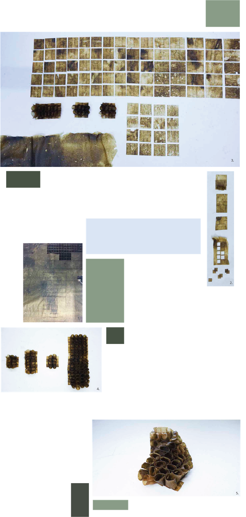
01| Lasercutting in the seaweed.

02| Trial in laser cutting:
      S(%)  P(%) F(%)
    1| 80,  60,  50 - no cut
    2| 70,  70,  50 - no cut
    3| 60,  80,  50 - partially cut
    4| 40,  80,  50 - partially cut
    5| 30,  80,  50 - partially cut
    6| 40,  90,  50 - cut
    7| 30,  90,  50 - cut
    8| 40,  100, 50 - cut (might burn a bit)
    9| 40,  95,  50 - cut : chosen

03| Overview over process.

04| Models of final cut outs, samples of different ways of interlocking, I realised that the cube folds
could be moved inside the cubes instead of outside, making the cube more sturdy. This is used in the
middle right sample and the final pieces to the outmost right.

05| Final piece in motion.
Further development, lasercutting and eching, every second model should be flipped in order for the interlocks to add up.
TOOLS
TURORIALS
- TRANSFORMATIVE MODULAR TEXTILE DESIGN
- FREEFORM ORIGAMI TESSELLATIONS BY GENERALIZING RESCH’S PATTERNS
- CIRCULAR FASHION 2022 - MODULAR SURFACES
- CIRCULAR FASHION 2022
- RHINO BASIC 1
- RHINO BASIC 2
- RHINO BASIC 3-1
- RHINO BASIC 3-2
- RHINO SUM UP