08 | WEARABLES
RESEARCH | IDEATION
This week I was occupied by my mind, focussed on more personal and emotional matters, than what was happening in the course. Thus I have had a more conceptual perspective to this weeks assignment, trying to bring my personal emotional world into the physical and trying to understand and my personal feelings through the assignment. Hence I was very fascinated by the idea of motors in relations to haptics. The notion that haptics is "bidirectional, the the sense that the information we can extract about an object's properties is linked to the movements made to perceive those properties" Lynette A. Jones, was very intriguing, as I statred to think about healing and dealing with emotions through haptical sensing. Could I possbly create a bodily sensation that would connect to and sooth an emotional state? Could tacticale surfaces create a haptical sensation by the use of vibration. In a sense like exactly as a vibrator does, creating presure by the interaction beteewn a kinetic movement, an object, a body and a mind. The mind being important as that is a huge part of a sensual experience, also with a vibrator.
I saw FLEUR HULLEMAN's work at DDW 2017, and immediately fell in love with her Porn for the Soul project. A collection of tactile ceramic objects that are meant to stimulate the eye, the touch and your emotions. By combining tactile ceramic objects with softer materials like feathers, fur and rubber, she creates some astonishing haptical sculptures. In the same year NIENKE HELDER displayed the collection Sexual Healing, a set of sensory objects that is meant to rehabilitate women who has experienced sexual abuse. This project is amazing as it is both aesthetically poetic and very functional, as it allows the women to reclaim both their body and emotions. This aspect of healing psycologically through physical sensations is very fascinating to me, and I belive that it is a bridge many people could benefit in crossing in dealing with difficult situations, regardless of what it is.
Another designer from the same year who also worked with sensuality and sensation is ROXANNE BRENNEN who explored eating sensations as a sexual foreplay. By creating ceramic dining utensils, she exprlores how eating can become a sensual expreience.
The notion of sensing your body to understand something non-bodily is really fascinating to me, as it maskes something intangible tangible.
A project touching upon the exploration of sexual pleasure through wearable technology is Lovewear by WITSENSE. The project explores how technology can be imbeded in knittied objects and garments to let individualt self-explore their sexuality. Withsense collaborated with a knitting company where they created state of the art seamless knitting allowing for the imbedding of inflatables and technology.
The same company also made Senseweare, a collection of wearable smart adn tactile garments that stimulate and improves wareness of senses.
Finally there is also the project Tactile Dialogues by MARTIJN TEN BHÖMER who made a smart-textile servise, in the shape of a pillow that helps the physical communication between a dimentia patient and a caregiver. This is also a very interesting project as it creates communication via the sense of touch and haptics when oral communication is not possible, thereby bridging the physical with a concept that is intangable.
- 01 | PORN FOR THE SOUL, 2017, FLEUR HULLEMAN
- 02 | SEXUAL HEALING, 2017, NIENKE HELDER
- 03 | DINING TOYS, 2017, ROXANNE BRENNEN
- 01 | LOVEWEAR, 2020, WITSENSE
- 01 | SENSEWEAR, 2016, WITSENSE
- 01 | TACTILE DIALOUGES, 2014, MARTIJN TEN BHÖMER
FABRIC ACADEMY SOURCES:
- Diane Wakim Le TextileLab Lyon 2020-21_
- Vicky Luan
- Loes Bogers TextileLab Amsterdam 2019-20_
- Sara Alvarez TextileLab Amsterdam 2020-21_
- Kate Reed
TOOLS
- ARDOUINO BOARD
- BREAD BOARD
- ALICATOR CLIPS
- 3V BATTERY
- PINS
- JUMPER WIRE
- 220, 1K, RESISTORS
- 2N222 TRANSISTOR
- 1N4001DIODE
- 0.1 uF CERAMIC CAP
- NPN TRANSISTOR
- VIBRATION MOTORS
- TEXTILES
- CONDUCTIVE THREAD
TUTORIAL
PROCESS | WORKFLOW
We had a bit of a problem getting all the different tools and materials for this week, so thermochromic inks, thin shape memory alloys and speakers was not something we had the possibility to try. Therefore I focused on the implication of the vibration motor, starting by doing the exercises with the motors shown in the tutorial WEARABLES. There after I tried to understand how the Ardouino codeing could be altered to create different vibration patterns. Finally I researched different textures with haptical properties when combined with vibration. I wanted to use the seaweed material as it is an interesting meeting, the very natural with the very technical.
GOOD TO KNOW | DRIVER CIRCUIT
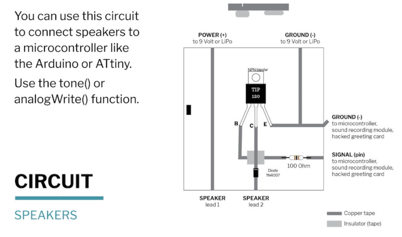
We started the week by creating a driver circuit, which we will use to test our actuators/outouts. A driver circuit is a component used to control another circuit by regulating the current flow, it is the interface between the microcontroller and the oputput component. The driver circuit is a tool that can be used when working with actuators wich requires more current, or a broader arrange of voltages that is provided by the Arduino Uno itself. Therefore we created a simple driver circuit using the following materials:
- A Piece of Cardboard
- Copper Tape
- Insulating tape
- NPN Bipolar TIP 120
- 1N4007 Diode
- 100 OHM resistor
- Scissors
- Pliers
- Soldering Gun
- Stand
- Soldering Flux
The driver circuit is connected to the Aruino UNO through the ground pin and an analog pin which are connected to the NPN Bipolar TIP 120 pins the ground to the E pin (most right) and the analog pin to the B pin (most left). the extra voltage is added by connecting a 9v battery, intergrated through connecting the (-) to the ground and the (+) directly to the sensor you want to connect. The Middle pin on the NPN is also connected directly to the sensor. The schematics are shown in the lecture by Emma Parechi:
GOOD TO KNOW | FLIP DOTS
After making the driver curcuit we tried the flip dot, coiling a insulated cunductive wire about 40 times aroun a pen and placing a magnet within the coil. When a current is added the magnet will flip, due to the electromagnetic field created by the current, when the current changes the magnet flip. The coil is connected to the circuit driver and the arduino using aligator clips in each end of the curl.
- Cardboard Circuit Driver.
- 9V Battery.
- Crocodile Clips.
- Arduino UNO R3.
- Enamled Copper wire (substituted with cheap jewellery wire I had got in Solstene Grene).
- A Square Magnet.
The flipdot method can be used in signs, and are also used in many interactive artworks such as climate Change Series shown in week 05.
GOOD TO KNOW | MOTORS
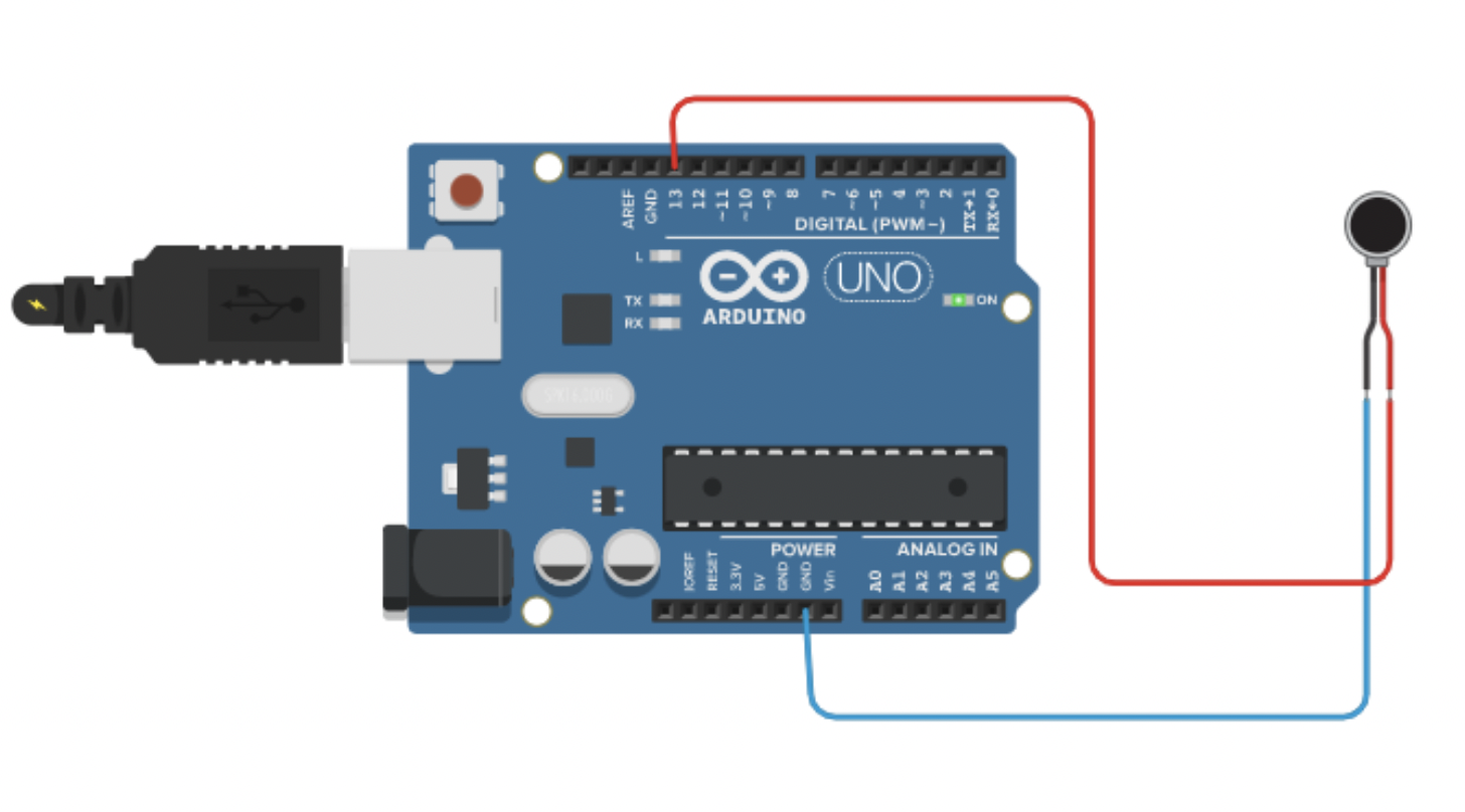
Due to my sensorial interest I focuused my week on understanding the vibration motor to create sensorial vibrations in textile surfaces. Margret had a similar interest so we decided to do the intitial coding and curcuits together. The motors we have here are coin vibration motors, a type of Eccentric Rotating Mass (ERM) motors, at 1 cm in diameter, similar to the ones that are used in the phones. The first step we did was to conncet this motor to a 3v baterry in a holder, using aligator clips.
GOOD TO KNOW | ARDUINO
We thereafter moved on to using the Arduino accoring to the sliders in the WEARABLES tutorial. First we connected the motor to pin 13 using the code for Builtin- LED blink. This worked like a charm and we tryed to alter the code to make the vibration sequence vary.
Coding a blink code to work with the motor.
/*
  Blink

  Turns an LED on for one second, then off for one second, repeatedly.

  Most Arduinos have an on-board LED you can control. On the UNO, MEGA and ZERO
  it is attached to digital pin 13, on MKR1000 on pin 6. LED_BUILTIN is set to
  the correct LED pin independent of which board is used.
  If you want to know what pin the on-board LED is connected to on your Arduino
  model, check the Technical Specs of your board at:
  https://www.arduino.cc/en/Main/Products

  modified 8 May 2014
  by Scott Fitzgerald
  modified 2 Sep 2016
  by Arturo Guadalupi
  modified 8 Sep 2016
  by Colby Newman

  This example code is in the public domain.

  https://www.arduino.cc/en/Tutorial/BuiltInExamples/Blink
*/

// the setup function runs once when you press reset or power the board
void setup() {
  // initialize digital pin LED_BUILTIN as an output.
  pinMode(LED_BUILTIN, OUTPUT);
}

// the loop function runs over and over again forever
void loop() {
  digitalWrite(LED_BUILTIN, HIGH);  // turn the LED on (HIGH is the voltage level)
  delay(1000);                      // wait for a second
  digitalWrite(LED_BUILTIN, LOW);   // turn the LED off by making the voltage LOW
  delay(1000);                      // wait for a second
}

Altering the vibration

// the loop function runs over and over again forever
void loop() {
  digitalWrite(LED_BUILTIN, HIGH);  // turn the LED on (HIGH is the voltage level)
  delay(500);                      // wait for a second
  digitalWrite(LED_BUILTIN, LOW);   // turn the LED off by making the voltage LOW
  delay(500);                      // wait for a second
}

Altering the vibration

// the loop function runs over and over again forever
void loop() {
  digitalWrite(LED_BUILTIN, HIGH);  // turn the LED on (HIGH is the voltage level)
  delay(2000);                      // wait for a second
  digitalWrite(LED_BUILTIN, LOW);   // turn the LED off by making the voltage LOW
  delay(2000);                      // wait for a second
}

Altering the vibration

// the loop function runs over and over again forever
void loop() {
  digitalWrite(LED_BUILTIN, HIGH);  // turn the LED on (HIGH is the voltage level)
  delay(2000);                      // wait for a second
  digitalWrite(LED_BUILTIN, LOW);   // turn the LED off by making the voltage LOW
  delay(500);                      // wait for a second
}
Altering the vibration

// the loop function runs over and over again forever
void loop() {
  digitalWrite(LED_BUILTIN, HIGH);  // turn the LED on (HIGH is the voltage level)
  delay(500);                      // wait for a second
  digitalWrite(LED_BUILTIN, LOW);   // turn the LED off by making the voltage LOW
  delay(2000);                      // wait for a second
}
Thereafter we tried to make a fadeing vibration by exchanging the LED with motor in the given Fade code. Here we played around twith delay and fadeamount.
Coding a fade code to work with the motor.
/*
  Fade

  This example shows how to fade an LED on pin 9 using the analogWrite()
  function.

  The analogWrite() function uses PWM, so if you want to change the pin you're
  using, be sure to use another PWM capable pin. On most Arduino, the PWM pins
  are identified with a "~" sign, like ~3, ~5, ~6, ~9, ~10 and ~11.

  This example code is in the public domain.

  https://www.arduino.cc/en/Tutorial/BuiltInExamples/Fade
*/

int motor = 9;         // the PWM pin the LED is attached to
int brightness = 0;  // how bright the LED is
int fadeAmount = 5;  // how many points to fade the LED by

// the setup routine runs once when you press reset:
void setup() {
  // declare pin 9 to be an output:
  pinMode(motor, OUTPUT);
}

// the loop routine runs over and over again forever:
void loop() {
  // set the brightness of pin 9:
  analogWrite(motor, brightness);

  // change the brightness for next time through the loop:
  brightness = brightness + fadeAmount;

  // reverse the direction of the fading at the ends of the fade:
  if (brightness <= 0 || brightness >= 255) {
    fadeAmount = -fadeAmount;
  }
  // wait for 30 milliseconds to see the dimming effect
  delay(30);
}

Altering the vibration: Fade amount

int motor = 9;         // the PWM pin the motor is attached to
int brightness = 0;  // how bright the motor is
int fadeAmount = 10;  // how many points to fade the motor by

// the setup routine runs once when you press reset:
void setup() {
  // declare pin 9 to be an output:
  pinMode(motor, OUTPUT);
}

// the loop routine runs over and over again forever:
void loop() {
  // set the brightness of pin 9:
  analogWrite(motor, brightness);

  // change the brightness for next time through the loop:
  brightness = brightness + fadeAmount;

  // reverse the direction of the fading at the ends of the fade:
  if (brightness <= 0 || brightness >= 255) {
    fadeAmount = -fadeAmount;
  }
  // wait for 30 milliseconds to see the dimming effect
  delay(30);

Altering the vibration: delay

int motor = 9;         // the PWM pin the motor is attached to
int brightness = 0;  // how bright the motro is
int fadeAmount = 10;  // how many points to fade the motor by

// the setup routine runs once when you press reset:
void setup() {
  // declare pin 9 to be an output:
  pinMode(motor, OUTPUT);
}

// the loop routine runs over and over again forever:
void loop() {
  // set the brightness of pin 9:
  analogWrite(motor, brightness);

  // change the brightness for next time through the loop:
  brightness = brightness + fadeAmount;

  // reverse the direction of the fading at the ends of the fade:
  if (brightness <= 0 || brightness >= 255) {
    fadeAmount = -fadeAmount;
  }
  // wait for 100 milliseconds to see the dimming effect
  delay(100);

Altering the vibration: delay

int motor = 9;         // the PWM pin the motor is attached to
int brightness = 0;  // how bright the motro is
int fadeAmount = 10;  // how many points to fade the motor by

// the setup routine runs once when you press reset:
void setup() {
  // declare pin 9 to be an output:
  pinMode(motor, OUTPUT);
}

// the loop routine runs over and over again forever:
void loop() {
  // set the brightness of pin 9:
  analogWrite(motor, brightness);

  // change the brightness for next time through the loop:
  brightness = brightness + fadeAmount;

  // reverse the direction of the fading at the ends of the fade:
  if (brightness <= 0 || brightness >= 255) {
    fadeAmount = -fadeAmount;
  }
  // wait for 100 milliseconds to see the dimming effect
  delay(2000);
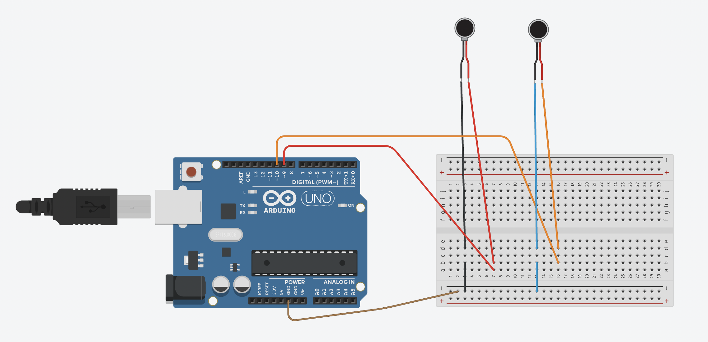
Codeing two motors:
After that we wanted to intergrate another motor, this we frist tested in Thinkercad, using the code for the blink. Adding more motors by "int" and defining the pin and name, see the code below.
/*
  Blink

  Turns an LED on for one second, then off for one second, repeatedly.

  Most Arduinos have an on-board LED you can control. On the UNO, MEGA and ZERO
  it is attached to digital pin 13, on MKR1000 on pin 6. LED_BUILTIN is set to
  the correct LED pin independent of which board is used.
  If you want to know what pin the on-board LED is connected to on your Arduino
  model, check the Technical Specs of your board at:
  https://www.arduino.cc/en/Main/Products

  modified 8 May 2014
  by Scott Fitzgerald
  modified 2 Sep 2016
  by Arturo Guadalupi
  modified 8 Sep 2016
  by Colby Newman

  This example code is in the public domain.

  https://www.arduino.cc/en/Tutorial/BuiltInExamples/Blink
*/
int motor1=9;
int motor2=10;

// the setup function runs once when you press reset or power the board
void setup() {
  // initialize digital pin LED_BUILTIN as an output.
  pinMode(motor1, OUTPUT);
  pinMode(motor2, OUTPUT);
}

// the loop function runs over and over again forever
void loop() {
  digitalWrite(motor1, HIGH);  // turn the LED on (HIGH is the voltage level)
  delay(2000);
  digitalWrite(motor2, HIGH);  // turn the LED on (HIGH is the voltage level)
  delay(500);                      // wait for a second
  digitalWrite(motor1, LOW);   // turn the LED off by making the voltage LOW
  delay(2000);
  digitalWrite(motor2, LOW);   // turn the LED off by making the voltage LOW
  delay(500);  // wait for a second

}
This was the code we used for the fist attempt:
*
  Smoothing

  Reads repeatedly from an analog input, calculating a running average and
  printing it to the computer. Keeps ten readings in an array and continually
  averages them.

  The circuit:
  - analog sensor (potentiometer will do) attached to analog input 0

  created 22 Apr 2007
  by David A. Mellis  <dam@mellis.org>
  modified 9 Apr 2012
  by Tom Igoe

  This example code is in the public domain.

  https://www.arduino.cc/en/Tutorial/BuiltInExamples/Smoothing
*/

// Define the number of samples to keep track of. The higher the number, the
// more the readings will be smoothed, but the slower the output will respond to
// the input. Using a constant rather than a normal variable lets us use this
// value to determine the size of the readings array.
const int numReadings = 10;

int readings[numReadings];      // the readings from the analog input
int readIndex = 0;              // the index of the current reading
int total = 0;                  // the running total
int average = 0;                // the average

int inputPin = A0;
int led_pin = 3; //change the pin of the Led

void setup() {
  // initialize serial communication with computer:
  Serial.begin(9600);
  // initialize all the readings to 0:
  for (int thisReading = 0; thisReading < numReadings; thisReading++) {
    readings[thisReading] = 0;
  }

    pinMode(led_pin, OUTPUT);   //initialize led pin
}

void loop() {
  // subtract the last reading:
  total = total - readings[readIndex];
  // read from the sensor:
  readings[readIndex] = analogRead(inputPin);
  // add the reading to the total:
  total = total + readings[readIndex];
  // advance to the next position in the array:
  readIndex = readIndex + 1;

  // if we're at the end of the array...
  if (readIndex >= numReadings) {
    // ...wrap around to the beginning:
    readIndex = 0;
  }

  // calculate the average:
  average = total / numReadings;


  // send it to the computer as ASCII digits
  Serial.println(average);
  average = map(average, 60, 230, 0, 255); //we change the range
  average = constrain(average, 0, 255); //we apply the limits

  delay(50);        // delay in between reads for stability
  analogWrite(led_pin, average);
}
For the next time I will try this turorial and code:
GOOD TO KNOW | SEAWEED AND ELECTRONICS
When I had a better understanding of working with the vibration motor I started working on intergrating it into a textile surface. I wanted to create a surface simulating a light touch, so I made seaweed sequins and glued them to monofilament to lift them off the surfave and transfere the vibrations. I attempted to have the sequins on a seaweed backing, using the left over cuttings from WEEK 03 naturally creating a pocket for the vibration motor. This did however not work as the vibration did not carry through the material. Thus I tried streaching a double layered polyester organza on a embroidery hoop to create a drum-skin, which I estimated to more adequate at carrying the vibration. The first of these tetste was fairly sucsessful when the motor was placed perpendicularly to the fabric.
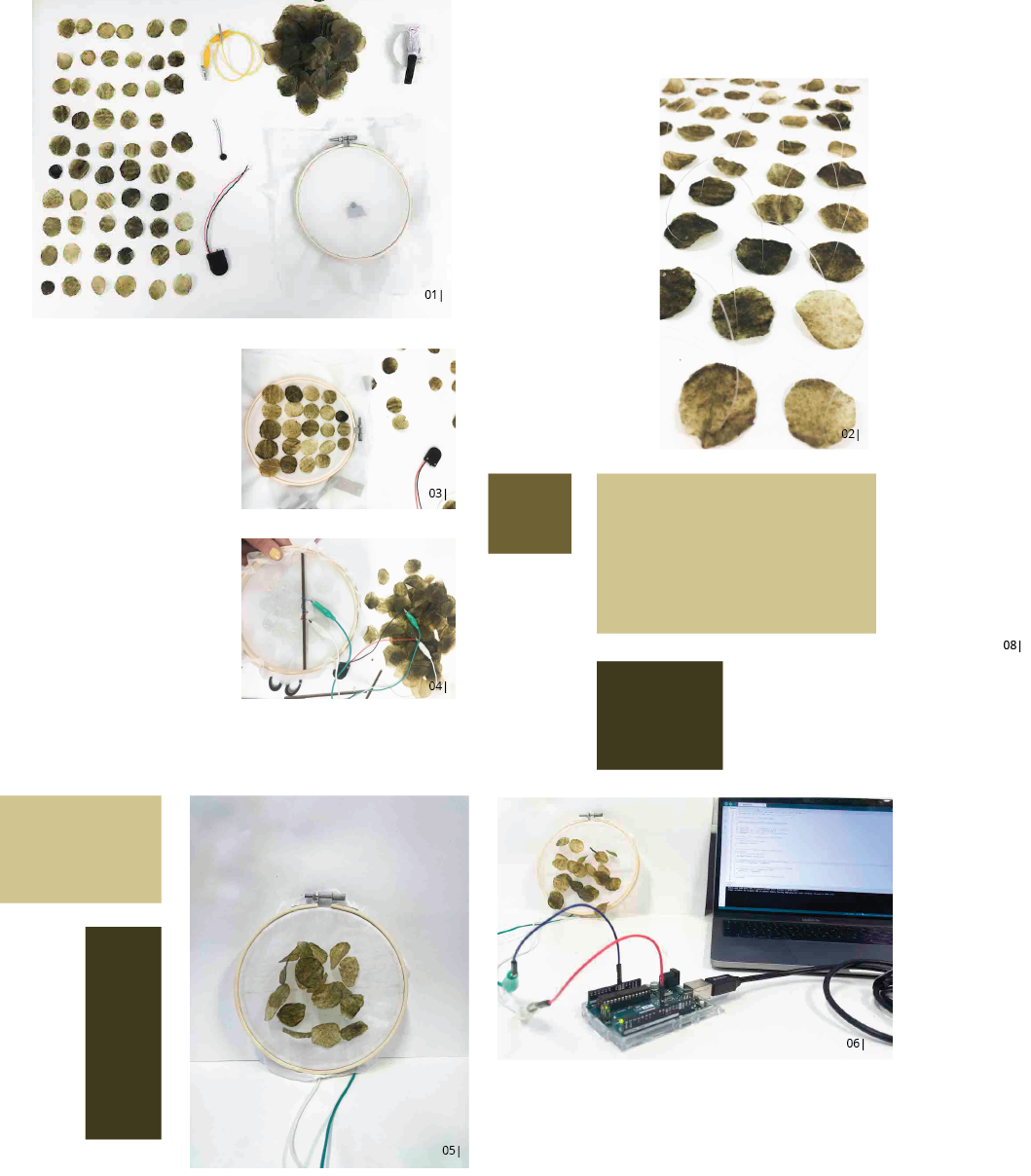
- 01 | TOOL SET, PHOTO ALBERTE BOJESEN
- 02 | SEQUINS, PHOTO ALBERTE BOJESEN
- 03 | SEQUENCE OF SEQUINS, PHOTO ALBERTE BOJESEN
- 04 | BACK SIDE THE MOTOR SECURED BY PLYWOOD, PHOTO ALBERTE BOJESEN
- 05 | SECOND SAMPLE ON POLYESTER, PHOTO ALBERTE BOJESEN
- 06 | CONNECTION TO ARDUINO, PHOTO ALBERTE BOJESEN
- 07 | SEQUINS ON SEAWEED BACKING, PHOTO ALBERTE BOJESEN
- 08 | FIRST SAMPLE ON POLYESTER, BLINK SEQUENCE, PHOTO ALBERTE BOJESEN
- 09 | SSECOND SAMPLE ON POLYESTER, FADE SEQUENCE, THIS SAMPLE WORKED BETTER DUE TO THE LENGTH OF THE MONOFILAMENT, PHOTO ALBERTE BOJESEN
- 10 | SECOND SAMPLE INTERACTION, PHOTO ALBERTE BOJESEN
Code:
/*
  Blink

  Turns an LED on for one second, then off for one second, repeatedly.

  Most Arduinos have an on-board LED you can control. On the UNO, MEGA and ZERO
  it is attached to digital pin 13, on MKR1000 on pin 6. LED_BUILTIN is set to
  the correct LED pin independent of which board is used.
  If you want to know what pin the on-board LED is connected to on your Arduino
  model, check the Technical Specs of your board at:
  https://www.arduino.cc/en/Main/Products

  modified 8 May 2014
  by Scott Fitzgerald
  modified 2 Sep 2016
  by Arturo Guadalupi
  modified 8 Sep 2016
  by Colby Newman

  This example code is in the public domain.

  https://www.arduino.cc/en/Tutorial/BuiltInExamples/Blink
*/
int motor1=9;
int motor2=10;

// the setup function runs once when you press reset or power the board
void setup() {
  // initialize digital pin LED_BUILTIN as an output.
  pinMode(motor1, OUTPUT);
  pinMode(motor2, OUTPUT);
}

// the loop function runs over and over again forever
void loop() {
  digitalWrite(motor1, HIGH);  // turn the LED on (HIGH is the voltage level)
  delay(2000);
  digitalWrite(motor2, HIGH);  // turn the LED on (HIGH is the voltage level)
  delay(500);                      // wait for a second
  digitalWrite(motor1, LOW);   // turn the LED off by making the voltage LOW
  delay(2000);
  digitalWrite(motor2, LOW);   // turn the LED off by making the voltage LOW
  delay(500);  // wait for a second

}
I found that the thickness of the monofilament is important for the sequins to be lifted off the surface, and I would have liked to use a thicker one, therefore the second polyester sample was the most successful as the length of the monofilament was shorter. The aesthetics of the seaweed is very nice and the vibrations carry quite well. I like the implications it have, with the vibrating sequins, making it appear very delicate, and you can also feel the vibrations when interacted with. I would like to be able to apply it on the body.
I would have also loved to have made vibrating seaweed gloves made for exploring your bady via vibration.