13 | SKIN ELECTRONICS
"In the same way that the wearables industry is integrating fashion practices in their development, we envision new partnerships between the biotech/tech companies and skin professionals such as makeup artists, prosthesis experts and tattooists in order to embrace the idea of human-device symbiosis. FX e-makeup made use of special effects makeup for hiding electronic components that sense facial muscle movements, acting as a second skin." (Katia Vega)
RESEARCH | SKIN ELECTRONICS
What interests me the most with skin electronics is the interaction possibilities you can explore on the body. However, I must admit that this is not my area of interest. So I used quite some time finding projects that explored topics that I find interesting and meaningful. The first project I found is Touch Me, a musical interface that responds musically to the shared touch between people. The interaction implications in this project are fascinating, as it gives feedback from the interactions between two humans.
Behnaz Farahi made another really exciting project, looking at brain activity. This 3D-printed helmet moves according to the wearer's brain activity, moving and lighting up according to the amount of activity. The more activity the more the helmet moves down over the face to "protect" the wearer.
I also really liked this project by MIT with working with tattoo interfaces and matrixes. The way you can interact with the computer via the skin is very exciting and I decided that that is what I am going to explore during this week.
I was also introduced to these project that shows different implications of skin electronics.
TOOLS
PROCESS | WORKFLOW
This week was ver divided as I also used a lot of time on my personal project, thus I had less time on this project than the previous projects, however as I have already decided that I will not workn with skin electronics I prioritised the personal project and focused this week on understanding the ATtiny and the matrix and Processing program.
GOOD TO KNOW | ATTINY
The first tutorial was about workig with the ATtiny module, which alows the code created through the ArduinoUno program to be used without the Arduino board and the computer connection. The tutorial was quite tricky as there were a lot of libraries and codes that needed to be downloaded and installed.
01 | Download
02 | Install this link https://raw.githubusercontent.com/damellis/attiny/ide-1.6.x-boards-manager/package_damellis_attiny_index.json
03 | Go to AriduinoIDE, Preferences, Add the link to Aditional Board Manager URLs:
04 | Add the AtTiny board by Tools, Board, Board Manager, Install: Attiny by Davis A. Mellis.
05 | Select Tools, Processor: ATtiny85
06 | Select Tools, Clock: 8MHz (internal)
07 | Select Tools, Programmer: Arduinoo as ISP
08 | Install this link  https://drazzy.com/package_drazzy.com_index.json
09 | Go to AriduinoIDE, Preferences, Add the link to Aditional Board Manager URLs:
10 | When adding an old or new ATtiny you need to clean it: Tools, BurnBootloader (can only be done by downloading above link.)
There after we tried the different schematics provided by Emma Pareschi The first code we used was the attiny_led:
/* Emma Pareschi, Nov 2019
 *
 *  the led connected to pin 1. it blinks
*/

int led_pin = 1;  //pin of the Led

void setup() {
  // put your setup code here, to run once:
  pinMode(led_pin, OUTPUT);   // set the pin 1 as OUTPUT

}

void loop() {
  // put your main code here, to run repeatedly:
  digitalWrite(led_pin, HIGH);      //turn the Led ON
  delay(1000);                //wait
  digitalWrite(led_pin, LOW);       //turn the Led OFF
  delay(1000);                //wait
}
Working LED with Arduino connected |
Working LED with Arduino disconnected and 3v battery |
The next code we used was the attiny_led_digtalsensor_1: This did not work when we tried it first, therefore we reconnected to the Arduino and added a transistor where after the disconnection worked.
/*
Emma Pareschi 2020
the Led turns on when the digital sensor is triggered
 */

// this constant won't change:
int sw_pin = 4;    // the pin that the pushbutton is attached to

int led_pin = 1; //pin of the led

// Variables will change:
int sw_status = 0;         // current state of the button

void setup() {
  // initialize input and output pins:
  pinMode(sw_pin, INPUT_PULLUP);
  pinMode(led_pin, OUTPUT);

}

void loop() {

  // read the pushbutton input pin:
  sw_status = digitalRead(sw_pin);

  // compare the switch status to its previous state
  if (sw_status == LOW) {   //if the sw is pressed
    digitalWrite(led_pin, HIGH);   //turn on the led (5V)
  } else {        //if the sw is not pressed
    digitalWrite(led_pin, LOW);   //turn off the Led (0V)
  }

}
Working LED with Arduino connected not working |
LED with Arduino disconnected not working |
Working LED with ... and Arduino connected |
Working LED with ... and Arduino disconnected, 3v battery |
GOOD TO KNOW | INTERFACES AND MATRIX
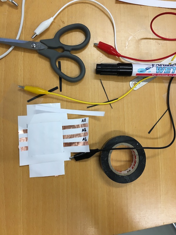
Matrices are described through a system of linear equations, more specifically a two dimensional vector with an input and output, according to the University of Utah. In electronics matrices are used to model the wireless signals and to optimise them. Matrices are used for detection, extractions and processing of the information embedded in signal. Using the program called Processing the electronic matrix alludes very much to the mathematical definition of being a system of linear equations and two dimensional vectors, as we are creating the matrix connected to the processing program as a linear conductive grid where the overlapping vectors creates an input when touched. We started the matrix by making a 3x3 interaction matrix. Shown in the picture below, using copper tape, vinyl and velostat. The velostat is placed inbetween the crossign cupper tape lines to avoid them interacting constantly.
When the matrix was done we downloaded the program called Prossessing. This allows one to interact with the matrix that is connected to the computer via the Arduino and draw in the prosessing program. By changeing the code in Arduino you can change the format of the processing sketch. However you can also change the sketch by downloading another from the Processing website
This is the original code for Arduino
 /*
Matrix: Kapton + Copper
A simple pressure sensor matrix made from two Kapton film sheets with
7×7 copper tape traces and a piece of Velostat or Eeonyx piezoresistive
material in between.
parsing through this grid by switching individual rows/columns to be
HIGH, LOW or INPUT (high impedance) to detect location and pressure.
>> http://howtogetwhatyouwant.at/
*/

#define numRows 3
#define numCols 3
#define sensorPoints numRows*numCols

int rows[] = {A0, A1, A2};
int cols[] = {5,6,7};
int incomingValues[sensorPoints] = {};

void setup() {
// set all rows and columns to INPUT (high impedance):
for (int i = 0; i < numRows; i++) {
  pinMode(rows[i], INPUT_PULLUP);
  }
for (int i = 0; i < numCols; i++) {
  pinMode(cols[i], INPUT);
  }
  Serial.begin(9600);
  }

void loop() {
  for (int colCount = 0; colCount < numCols; colCount++) {
    pinMode(cols[colCount], OUTPUT); // set as OUTPUT
    digitalWrite(cols[colCount], LOW); // set LOW
    for (int rowCount = 0; rowCount < numRows; rowCount++) {
      incomingValues[colCount * numRows + rowCount] = analogRead(rows[rowCount]); // read INPUT
      }// end rowCount
      pinMode(cols[colCount], INPUT); // set back to INPUT!
    }// end colCount

    // Print the incoming values of the grid:
    for (int i = 0; i < sensorPoints; i++) {
      Serial.print(incomingValues[i]);
      if (i < sensorPoints - 1)
      Serial.print("\t");
      }
      Serial.println();
      delay(10);
      }
This is the original code for Processing
import processing.serial.*;

/*
Code based on Tom Igoe’s Serial Graphing Sketch
>> http://wiki.processing.org/w/Tom_Igoe_Interview
Reads X analog inputs and visualizes them by drawing a grid
using grayscale shading of each square to represent sensor value.
>> http://howtogetwhatyouwant.at/
Working with a matrix
*/


String myString = null;
String inString = null;
int lf = 10;    // Linefeed in ASCII

Serial myPort; // The serial port
int rows = 3;
int cols = 3;
int maxNumberOfSensors = rows*cols;
float[] sensorValue = new float[maxNumberOfSensors]; // global variable for storing mapped sensor values,
float[] previousValue = new float[maxNumberOfSensors]; // array of previous values
int ellipseSize = 0;
int ellipseX;
void setup () {
size(600, 600); // set up the window to whatever size you want
ellipseSize = width/rows;

//println(Serial.list()); // List all the available serial ports
String portName = Serial.list()[5]; // set the number of your serial port!
myPort = new Serial(this, portName, 9600);
myPort.clear();
myPort.bufferUntil('\n'); // don’t generate a serialEvent() until you get a newline (\n) byte
background(0,0,255); // set inital background
smooth(); // turn on antialiasing
ellipseMode(CENTER); //define the position of the ellipse from its center
//ellipseMode(CORNER); //define the position of the ellipse from its corner
}

void draw () {
for (int i = 0; i < maxNumberOfSensors; i++) {
fill(sensorValue[i]-28,sensorValue[i]-28, sensorValue[i]-28); //Define first colour of the ellipse
ellipse(ellipseX + ellipseSize/2, ellipseSize * (i%rows) + ellipseSize/2, ellipseSize*(1-sensorValue[i]/255), ellipseSize*(1-sensorValue[i]/255)); //top left
if((i+1) % rows == 0) ellipseX += ellipseSize;
}
ellipseX=0;
}

void serialEvent (Serial myPort) {
inString = myPort.readStringUntil(lf); // get the ASCII string
println("test");
if (inString != null) { // if it’s not empty
inString = trim(inString); // trim off any whitespace
int incomingValues[] = int(split(inString, "\t")); // convert to an array of ints

if (incomingValues.length <= maxNumberOfSensors && incomingValues.length > 0) {
for (int i = 0; i < incomingValues.length; i++) {
// map the incoming values (0 to 1023) to an appropriate gray-scale range (0-255):
sensorValue[i] = map(incomingValues[i], 0, 1023, 0, 255); // stretch 5×5, because sensor value = 255 at rest (without pressure)
//incomingValue decreases with pressure because it is the resistance
sensorValue[i] = constrain(incomingValues[i], 0, 255); // stretch 5×5
println(sensorValue[i]); // print value to see

}
}
}
}
By chenging in the code different actions can be taken:
I used Louise Massacrier's documentation to understand the different components of the code.
GOOD TO KNOW | MY PROJECT
I made a seaweed interface using my seaweed sequins, velostat and conductive fbric. I glued the seaweed and the fabric using superglue and then checked the concections using the multimeter.
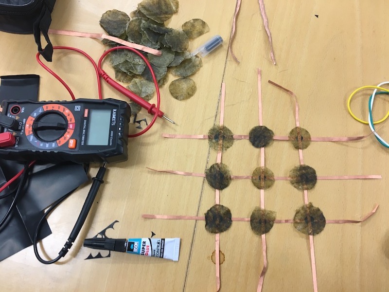
When the connections were working I connected the Arduino to the interface and the computer. Using the above code for Arduino I checked the workings of the matrix I made:
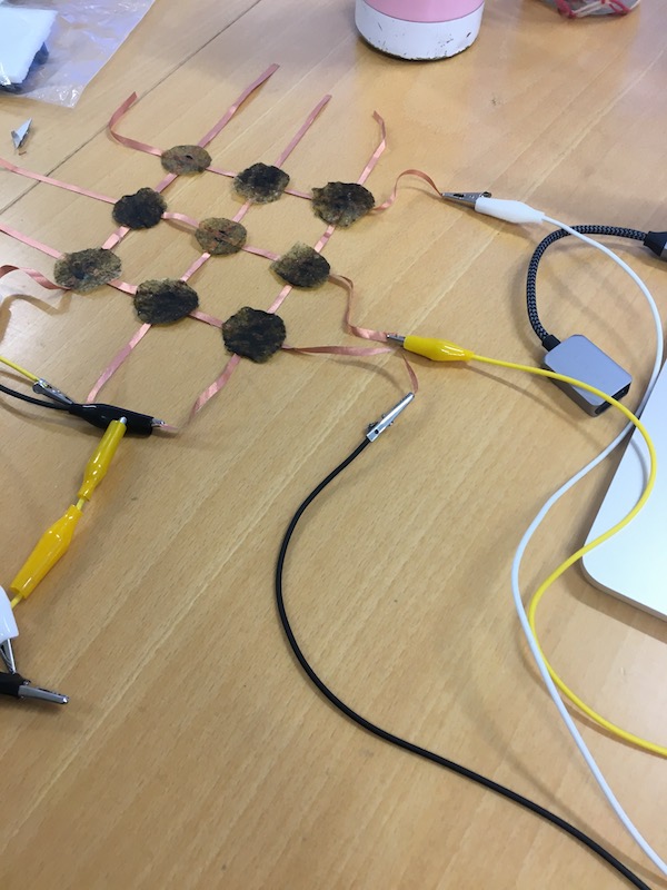
The final thing before starting working in the processor program is making sure the port is correct, for my computer it is 1 or 2. There after I played around with the square code, changeing the colours with RGB numbers.
Square code, Prossessing:
/*
Code based on Tom Igoe’s Serial Graphing Sketch
>> http://wiki.processing.org/w/Tom_Igoe_Interview
Reads X analog inputs and visualizes them by drawing a grid
using grayscale shading of each square to represent sensor value.
>> http://howtogetwhatyouwant.at/
*/

import processing.serial.*;

Serial myPort; // The serial port
int rows = 3;
int cols = 3;
int maxNumberOfSensors = rows*cols;
float[] sensorValue = new float[maxNumberOfSensors]; // global variable for storing mapped sensor values
float[] previousValue = new float[maxNumberOfSensors]; // array of previous values
int rectSize = 0;
int rectY;
void setup () {
size(600, 600); // set up the window to whatever size you want
rectSize = width/rows;

println(Serial.list()); // List all the available serial ports
String portName = Serial.list()[1]; // set the number of your serial port!
myPort = new Serial(this, portName, 9600);
myPort.clear();
myPort.bufferUntil('\n'); // don’t generate a serialEvent() until you get a newline (\n) byte
background(255); // set inital background
smooth(); // turn on antialiasing
rectMode(CORNER);
}

void draw () {
for (int i = 0; i < maxNumberOfSensors; i++) {
fill(2,sensorValue[i], 0);
rect(rectSize * (i%rows), rectY, rectSize, rectSize); //top left
if((i+1) % rows == 0) rectY += rectSize;
}
rectY=0;
}

void serialEvent (Serial myPort) {
String inString = myPort.readStringUntil('\n'); // get the ASCII string
println("test");
if (inString != null) { // if it’s not empty
inString = trim(inString); // trim off any whitespace
int incomingValues[] = int(split(inString, "\t")); // convert to an array of ints

if (incomingValues.length <= maxNumberOfSensors && incomingValues.length > 0) {
for (int i = 0; i < incomingValues.length; i++) {
// map the incoming values (0 to 1023) to an appropriate gray-scale range (0-255):
sensorValue[i] = map(incomingValues[i], 0, 1023, 0, 255); // stretch 5×5
println(sensorValue[i]); // print value to see
}
}
}
}
Ellipse code, Prossessing:
/*
Code based on Tom Igoe’s Serial Graphing Sketch
>> http://wiki.processing.org/w/Tom_Igoe_Interview
Reads X analog inputs and visualizes them by drawing a grid
using grayscale shading of each square to represent sensor value.
>> http://howtogetwhatyouwant.at/
*/

import processing.serial.*;

Serial myPort; // The serial port
int rows = 3;
int cols = 3;
int maxNumberOfSensors = rows*cols;
float[] sensorValue = new float[maxNumberOfSensors]; // global variable for storing mapped sensor values
float[] previousValue = new float[maxNumberOfSensors]; // array of previous values
int rectSize = 0;
int rectY;
void setup () {
size(600, 600); // set up the window to whatever size you want
rectSize = width/rows;

println(Serial.list()); // List all the available serial ports
String portName = Serial.list()[1]; // set the number of your serial port!
myPort = new Serial(this, portName, 9600);
myPort.clear();
myPort.bufferUntil('\n'); // don’t generate a serialEvent() until you get a newline (\n) byte
background(255); // set inital background
smooth(); // turn on antialiasing
rectMode(CORNER);
}

void draw () {
for (int i = 0; i < maxNumberOfSensors; i++) {
fill(sensorValue[i]);
rect(rectSize * (i%rows), rectY, rectSize, rectSize); //top left
if((i+1) % rows == 0) rectY += rectSize;
}
rectY=0;
}

void serialEvent (Serial myPort) {
String inString = myPort.readStringUntil('\n'); // get the ASCII string
println("test");
if (inString != null) { // if it’s not empty
inString = trim(inString); // trim off any whitespace
int incomingValues[] = int(split(inString, "\t")); // convert to an array of ints

if (incomingValues.length <= maxNumberOfSensors && incomingValues.length > 0) {
for (int i = 0; i < incomingValues.length; i++) {
// map the incoming values (0 to 1023) to an appropriate gray-scale range (0-255):
sensorValue[i] = map(incomingValues[i], 0, 1023, 0, 255); // stretch 5×5
println(sensorValue[i]); // print value to see
}
}
}
}
For further exploration into the processing I would follow this tutorial, Processing
GOOD TO KNOW | BOM
| Qty | Description | Price | Link | Notes |
|---|---|---|---|---|
| 1 | Arduino UNO | 24 € | h https://store.arduino.cc/products/arduino-uno-rev3 | |
| 1 | Attiny | 21 € | https://www.amazon.de/s?k=attiny85&language=en_GB&adgrpid=84995453747&hvadid=394625441254&hvdev=c&hvlocphy=2352&hvnetw=g&hvqmt=b&hvrand=12452655023581447617&hvtargid=kwd-3500996664&hydadcr=29373_1787238&tag=googdemozdesk-21&ref=pd_sl_17k1m27ved_bgclid=CjwKCAjwge2iBhBBEiwAfXDBR3-gCwuQ0CpPjp6jn7MsDJ7koUtC5ZXG_6etJ9LxwvuiI1G6i2qtmhoC1FkQAvD_BwE | PLA filament roll |
| 10 cm | Conductive copper fabric | 40 € | https://nano3dsystems.com/product/copper-conductive-fabric/ | depending on size |
| 1 | Bread board and pins | 14 € | https://www.amazon.de/s?k=breadboards&language=en_GB&adgrpid=81818479123&hvadid=394601758983&hvdev=c&hvlocphy=2352&hvnetw=g&hvqmt=e&hvrand=11118217909076086826&hvtargid=kwd-320119583954&hydadcr=4896_1792547&tag=googdemozdesk-21&ref=pd_sl_85ezu4gbdl_e | |
| 1 | 3 v holder | 7 € | https://www.amazon.com/3v-battery-holder/s?k=3v+battery+holder | 6 holders |
| 1 | 3 v battery | 5 € | https://www.amazon.com/dp/B085TB5RDX/ref=sspa_dk_detail_4?pd_rd_i=B085TB5RDX&pd_rd_w=XjuFK&content-id=amzn1.sym.eb7c1ac5-7c51-4df5-ba34-ca810f1f119a&pf_rd_p=eb7c1ac5-7c51-4df5-ba34-ca810f1f119a&pf_rd_r=JGG7BZ3RPHQ7QHCNA0VJ&pd_rd_wg=ql8Ej&pd_rd_r=8e60d7e2-2c09-41ac-88e9-9fcfb5ae44b6&s=electronics&sp_csd=d2lkZ2V0TmFtZT1zcF9kZXRhaWw&spLa=ZW5jcnlwdGVkUXVhbGlmaWVyPUEzME0ySDRJQkJES1NZJmVuY3J5cHRlZElkPUEwMDA2MjE2NUxOQ1pYSVI1RFozJmVuY3J5cHRlZEFkSWQ9QTA1MTQ3NDMyTTA2TEpOVFYyTzhIJndpZGdldE5hbWU9c3BfZGV0YWlsJmFjdGlvbj1jbGlja1JlZGlyZWN0JmRvTm90TG9nQ2xpY2s9dHJ1ZQ&th=1 | 10 pack |
| 1 | velostat | 5 € | https://www.adafruit.com/product/1361 | |
| 1-9 |