8. Wearables
„The great aim of education is not knowledge but action.” Herbert Spencer
Even though we had to experiment in team, I needed additional guidance and explanations. This week I was in the shoes of the students: I practiced a lot, learned new things.
Research
step 1 - watching tutorials
Watching tutorials by Emma Pareschi and tutorials from last year by Liza Stark.

step 2 - brainstorming
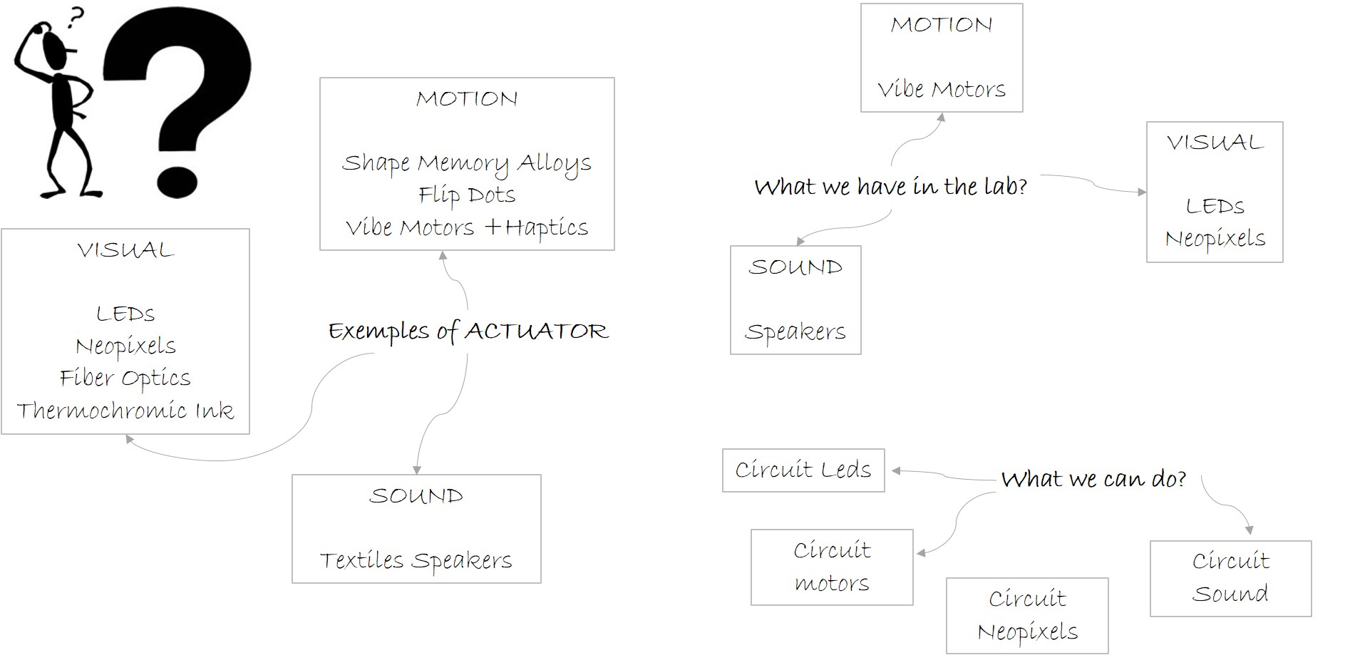
I organized a brainstorming, for finding answers to the questions: Wath is an actuators? What I have in the laborator? and What I can done?
References & Inspiration
An inspiration for this week was Lara Flores' page Laura Flores
https://class.textile-academy.org/2022/laura-flores/assignments/week10/
... and Internet search - Pinterest

PROJECT 1 - LEDS
Tools and materials
Process and workflow
step 1 - circuit and code
For the beginning I created an actuator sample and tested with ATTiny, choosing an example with LEDs.
The code for this circuit was written in the C++program.
int Sensor = 2;
int Led = 1;
void setup() {
  pinMode(Led, OUTPUT);
  pinMode(Sensor, INPUT);
}

void loop() {

   if (digitalRead(Sensor) == HIGH) {
      digitalWrite (Led, HIGH);
  }
   if (digitalRead(Sensor) == LOW) {
      digitalWrite (Led, LOW);
  }
}
ATTINY85 - this development board is based on the Attiny85 microcontroller, and is similar to Arduino Development Boards, the only difference being the much smaller size. It also retains the ability to add expansion boards according to the needs of your projects, and uses the same Arduino IDE programming language. It can be powered either directly through the USB 5V slot or using an external power supply with a voltage between 7 - 35V ( recommended being 12V or less ) connected to the dedicated pins. Technical characteristics: Power supply voltage: 5v (via USB slot) or 7 - 35V (using an external source)Support for Arduino IDE 1.0 + (OSX/Win/Linux)Regulator 500mA 5VI / O Pins: 6Flash memory: 8KBInterface: I2C / SPI.
Light Intensity Sensor Module for Arduino - the photoresistor module is useful for detecting the presence of light. The module has two LEDs, one for power and the other for comparator output. In this configuration, the circuit detects if the light exceeds a certain threshold. Specifications: Working voltage 3.3 V-5V.
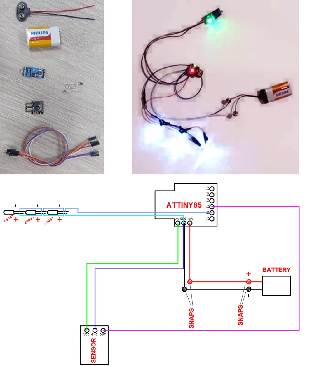
How the circuit works we can see in the video what follows:
step 2 - integrating the circuit into the project
This circuit I repeated, so it could be integrated into a clothing product.
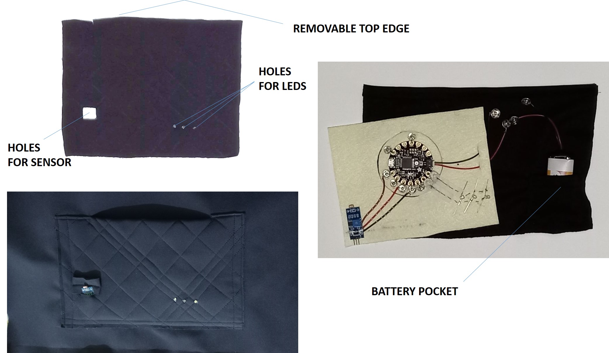
I made a pocket that lights up when it gets dark outside or in the room.
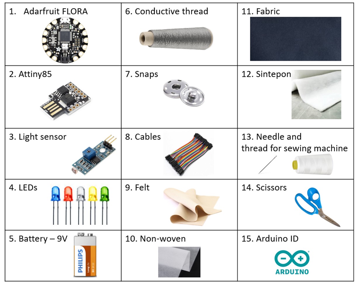
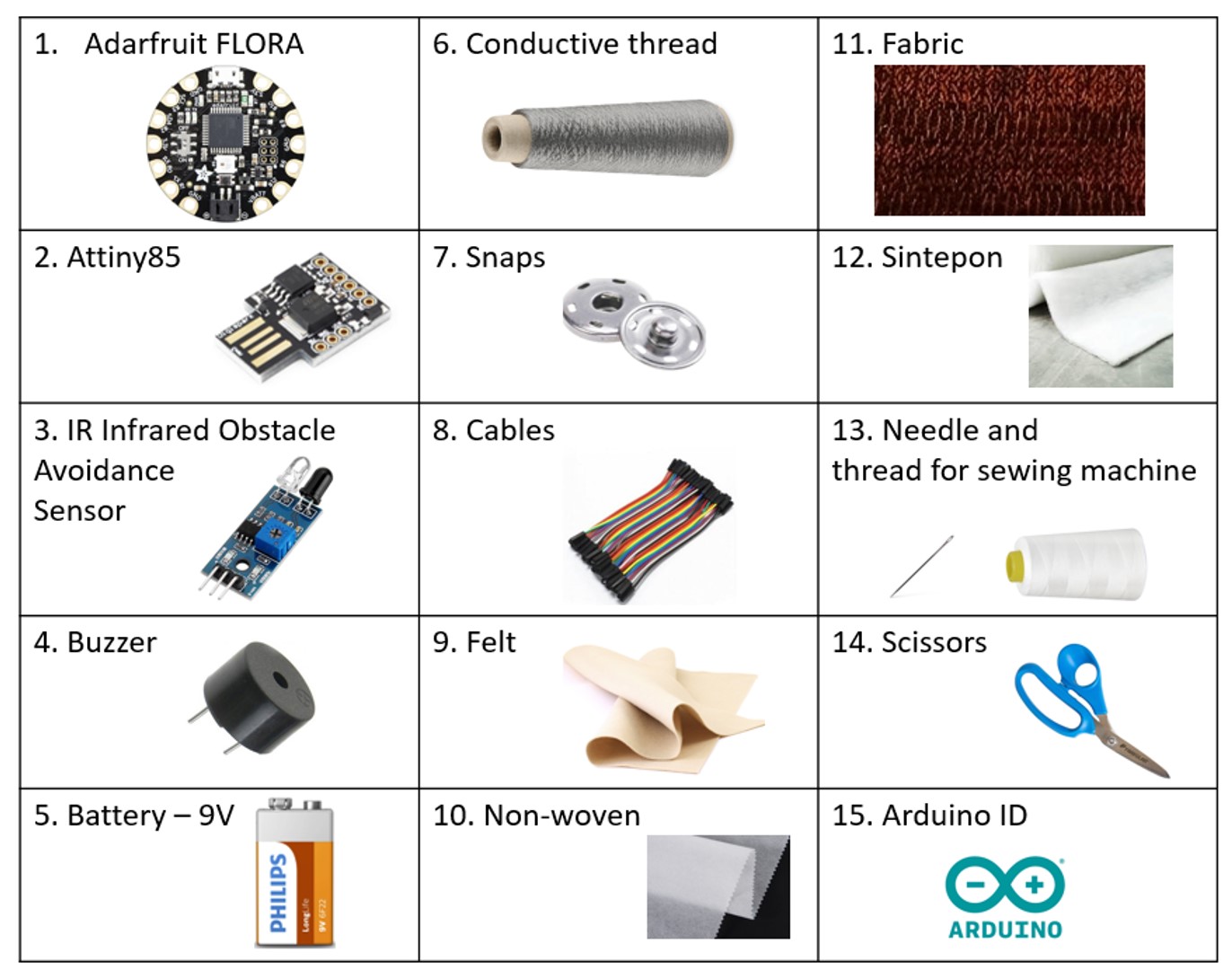
I used: adarfruit FLORA, the same light sensor, conductive thread, felt, non-woven, snaps, 3 LEDs, battery connector and a 9V battery.
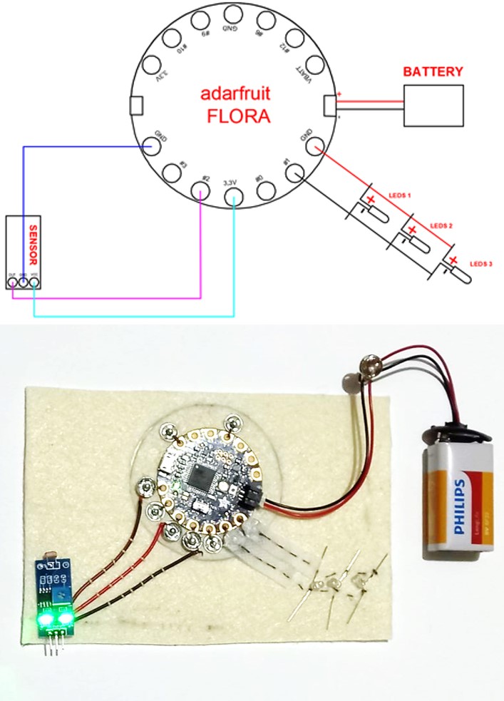
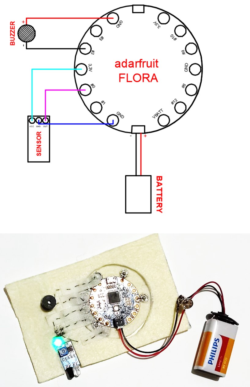
Adarfruit FLORA - FLORA is Adafruit's fully-featured wearable electronics platform. It's a round, sewable, Arduino-compatible microcontroller designed to empower amazing wearables projects. The FLORA has built-in USB support. FLORA has a small but easy to use onboard reset button to reboot the system. The power supply is designed to be flexible and easy to use. There is an onboard polarized 2 JST battery connector with protection schottky diode for use with external battery packs from 3.5v to 16v DC in. FLORA has onboard power switch connected to 2A power FET for safe and efficient battery on/off control, so you can power quite a bit without burning out your switch. The FLORA has an onboard 3.3v 250mA regulator with a protection diode and USB fuse so that the microcontroller voltage is consistent and can power common 3.3v modules and sensors.
Because I only had an ADARFRUIT FLORA, I sewed buttons to it (with conductive thread), so now I can use it for other projects.
The code on FLORA is the same one I uploaded to ATTINY85 earlier.
For connecting the LEDs I used conductive thread. To attach the light sensor I used cables, the cables I soldered to the sensor, on felt I fixed them with sewing thread.
The following picture shows the sewn circuit and the scheme.
I integrated the circuit in my pocket (photo and video below).
PROJECT 2 - SPEAKER (BUZZER)
Tools and materials
Process and workflow
step 1 - circuit and code
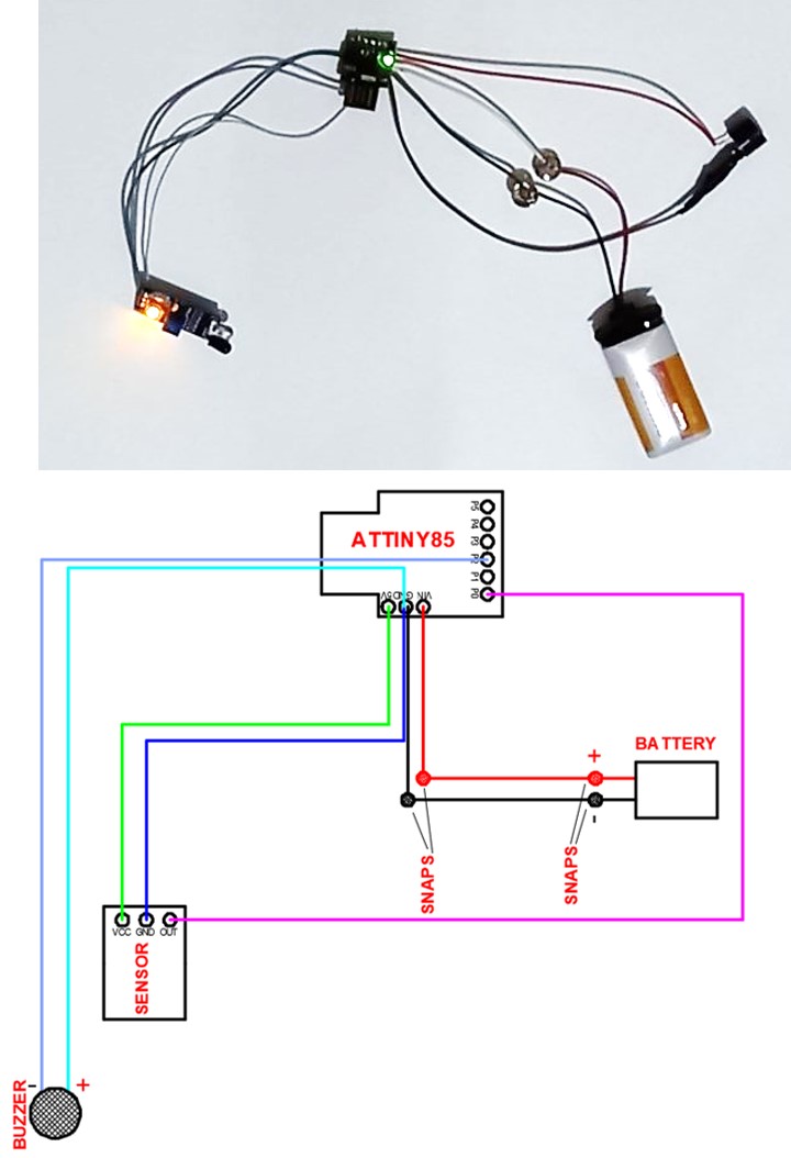
For the beginning I created an actuator sample and tested with ATTiny, choosing an example with SPEAKER (BUZZER).
The code was also written in C++
int Sensor_obst = 0;
int Sunet = 2;
void setup() {
  pinMode(Sunet, OUTPUT);
  pinMode(Sensor_obst, INPUT);
}

void loop() {
  int Obstacol = digitalRead(Sensor_obst);

   if ( Obstacol == LOW) {
      digitalWrite (Sunet, HIGH);
  }
   else  {
      digitalWrite (Sunet, LOW);
  }
}
ATTINY85 - description in the previous project.
IR Infrared Obstacle Avoidance Sensor - when the module detects an obstacle in front of the signal, the green indicator lights at the plate level, while the out port supports the low signal output, the module detects the distance of 2 ~ 30cm, the detection angle 35, the distance can detect the clockwise adjusted potential, detect the increase in distance; counterclockwise controls the potentiometer, reducing the detection distance. The active detection of infrared sensor sensor, the target reflection and therefore the shape is critical detection distance. If the minimum detection distance black, white, maximum; small objects away from a small area, a large area from the Grand. The output port of the sensor module output port can be directly connected to the IO microcontroller can also be directly drive a 5V relay; connection: VCC-VCC; GND-GND; OUT-IO. lm393 comparators, stable. The module can be powered at a voltage of 3-5V. when the power is turned on, the red power indicator lights up. With 3mm screw holes, easy fixed installation. Board size: 3.2 CM * 1.4 CM. Each module has been transmitted voltage threshold comparator adjusted by potentiometer.
Buzzer - The main function of this is to convert the signal from audio to sound. It includes two pins namely positive and negative. The positive terminal of this is represented with the ‘+’ symbol or a longer terminal. This terminal is powered through 6Volts whereas the negative terminal is represented with the ‘-‘symbol or short terminal and it is connected to the GND terminal.
Bit below you can see how the circuit works.
step 2 - integrating the circuit into the project
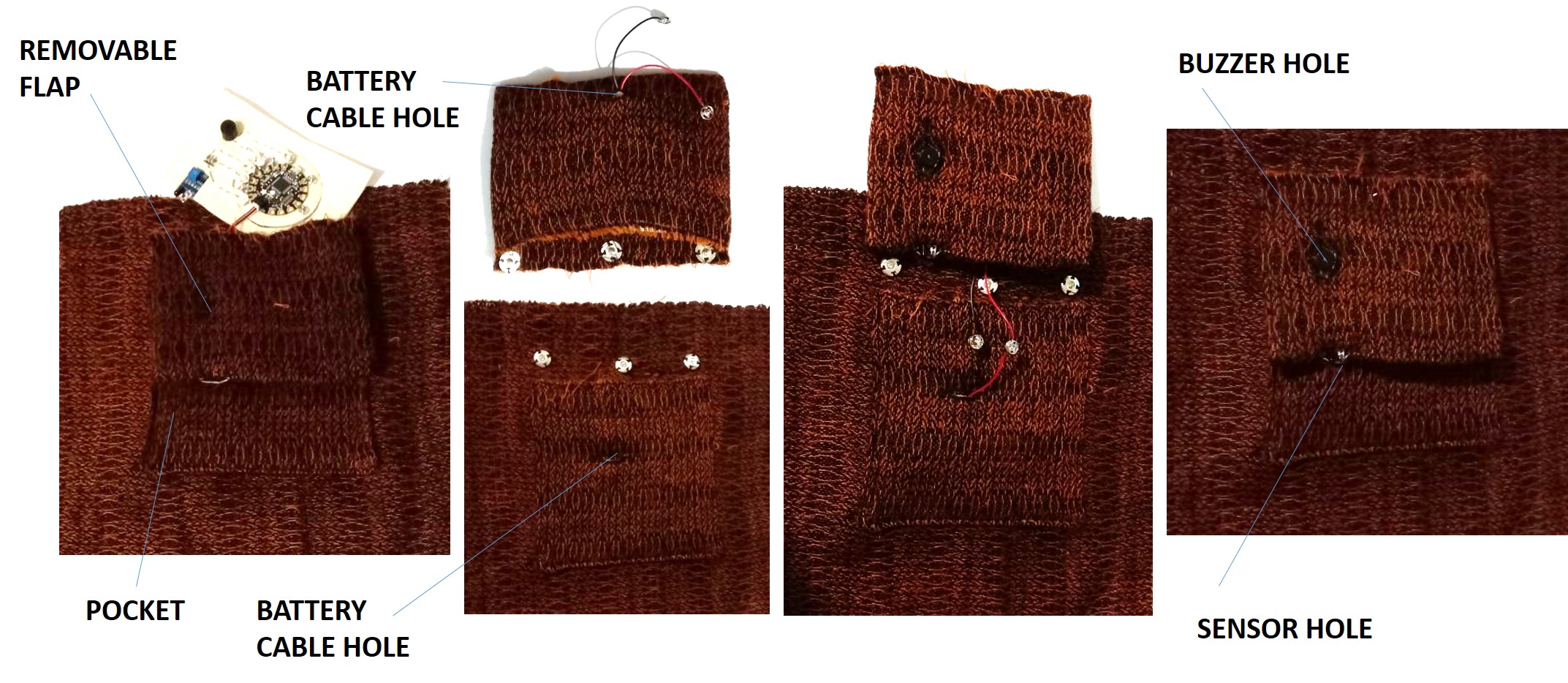
I sewed another pocket. When someone gets too close, the pocket (buzzer) will make a sound.
I used: adarfruit FLORA, the same IR Infrared Obstacle Avoidance Sensor, buzzer, conductive thread, felt, non-woven, snaps, battery connector and a 9V battery.
I used the same FLORA (from the previous project). I uploaded the code for this circuit.
The code on FLORA is the same one I uploaded to ATTINY85 earlier.
To connect the sensor and the buzzer I used conductive thread.
The following picture shows the sewn circuit and the scheme.
I integrated the circuit in the pocket (photo and video below).
The following video shows how the sound circuit works and how to disassemble the pocket.
Conclusions
This week I learned how to program ATTINITY and Adarftuit. I made some nice projects with input and output data: light and led sensor, obstacle overcoming sensor and buzzer. Complicated tasks, but I am very thankful that I was able to complete them.