5. E-textiles
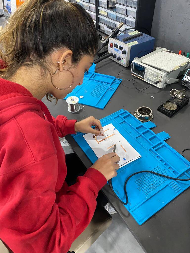
This week was a new adventure we went from cooking in the kitchen to exploring an electrical workshop full of wires and batteries, I learned a lot and had so much fun
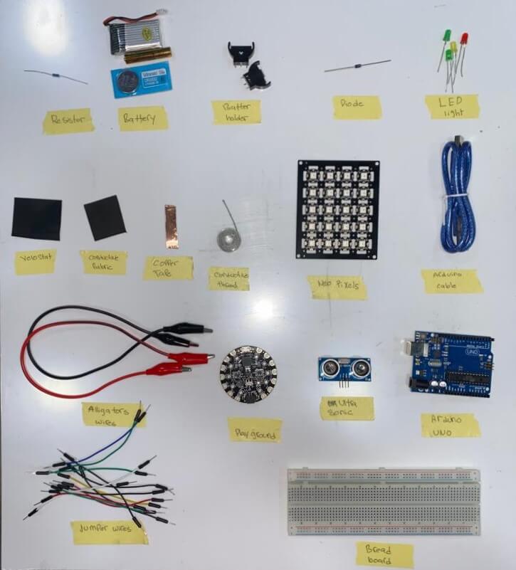
Getting Ready
Getting ready for our journey looked like this
Back to School
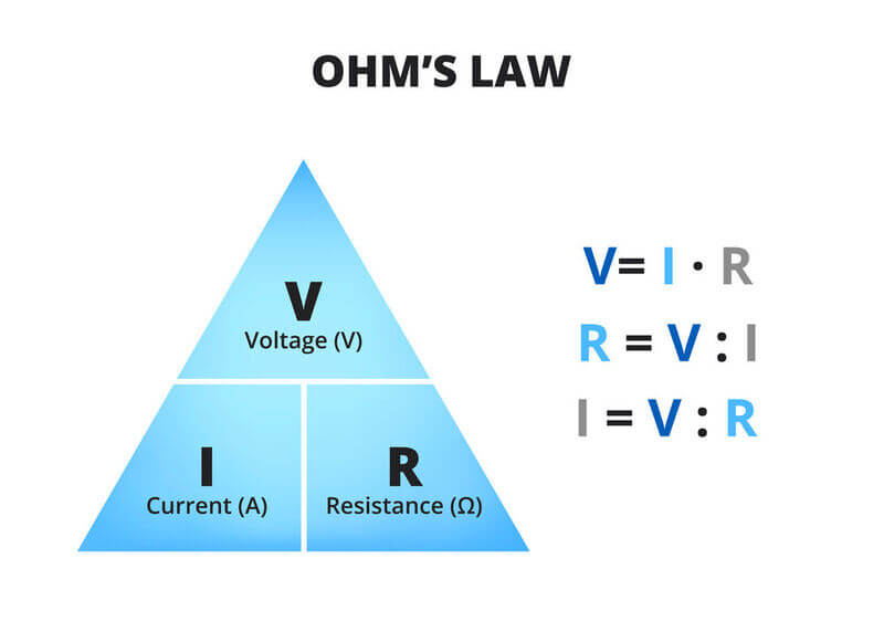
Ohm's law
states that the current through a conductor is proportional to the voltage across the conductor
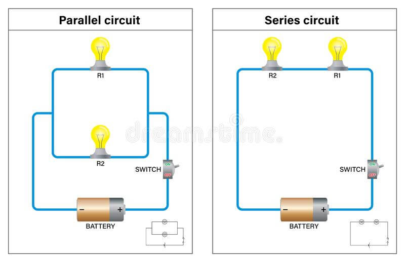
parallel & series Circuits
The difference between parallel and series circuits is the current flow
according to the picture:
in the series circuit the current comes out from the positive side of the battery all the way throw the conductor (the wires) and the same current go to the 2 LEDS so each one gets half of the currents power, and if one LED is burnt or ruined the whole circuit goes down
but in the Parallel circuits the current splits in two so each LED can get the same amount of electric current, and if one LED is ruined or broken the other one keeps going on
The Multimeter
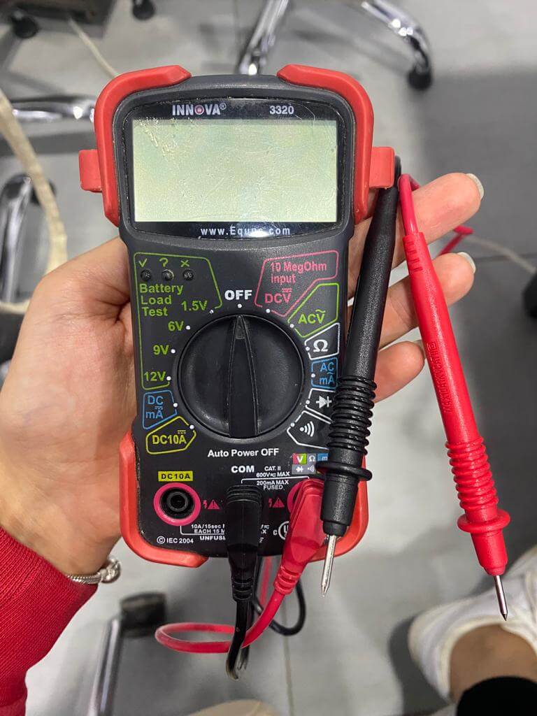
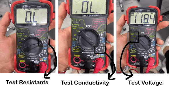
As everyone said multimeter is your best friend when it comes to electricity, It is a measuring instrument that can measure multiple electrical properties ( VOLTAGE, RESISTANCE & CURRENT/CONDUCTIVITY ) - Voltage: You have 4 options when it comes to voltage ( 1.5V, 6V, 9V, 12V ) depending on what type of battery you are measuring, you can not measure a 5V battery using the 1.5V icon
-
Resistance: You can measure the Ohm's of your resistance using multimeter by touching both ends of the resistance
-
Conductivity: A conductive material means it allows electrical current to pass through it, if you touch a material with both wires and the multimeter peeps means it is conductive and if you touch two points is a circuit and the multimeter dose not make a sound means there is something wrong with the circuit not electrical current can pass through
As shown in the picture it each icon refers to a different function
Soldering
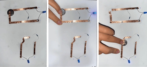
Soldering was fun !!
We made two closed circuits one parallel and one series using (copper tape, LED light, resister and a 3V battery)
Prototyping
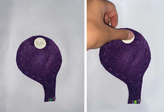
This was my first circuit I used a conductive thread, battery, felt and LED light
I started with sewing the LDE from the positive side and stopped in the middle of the shape, then sewing the negative side of the LED until I reached the thread used for sewing the positive side, I made a pocket to cover the battery with a thread in the meddle so the battery can touch the thread to close the circuit, So now the positive side of the battery is touching the positive thread and the negative side of the battery is place on top of the negative stiches, So when you push it becomes a closed circuit and the LED lights up
Arduino
Arduino is and open-source Prototyping platform that allows users to create an interactive electronic object, Arduino code is written in C++
To use Arduino you will need a microcontroller board based on a microchip that reads Arduino, a breadboard, jumper cables, resistance and LED lights
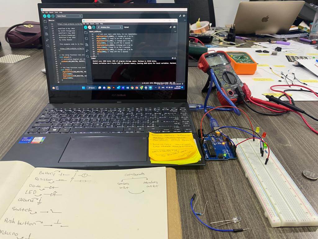 - Connect the Microcontroller to your laptop and start prototyping a circuit on your breadboard
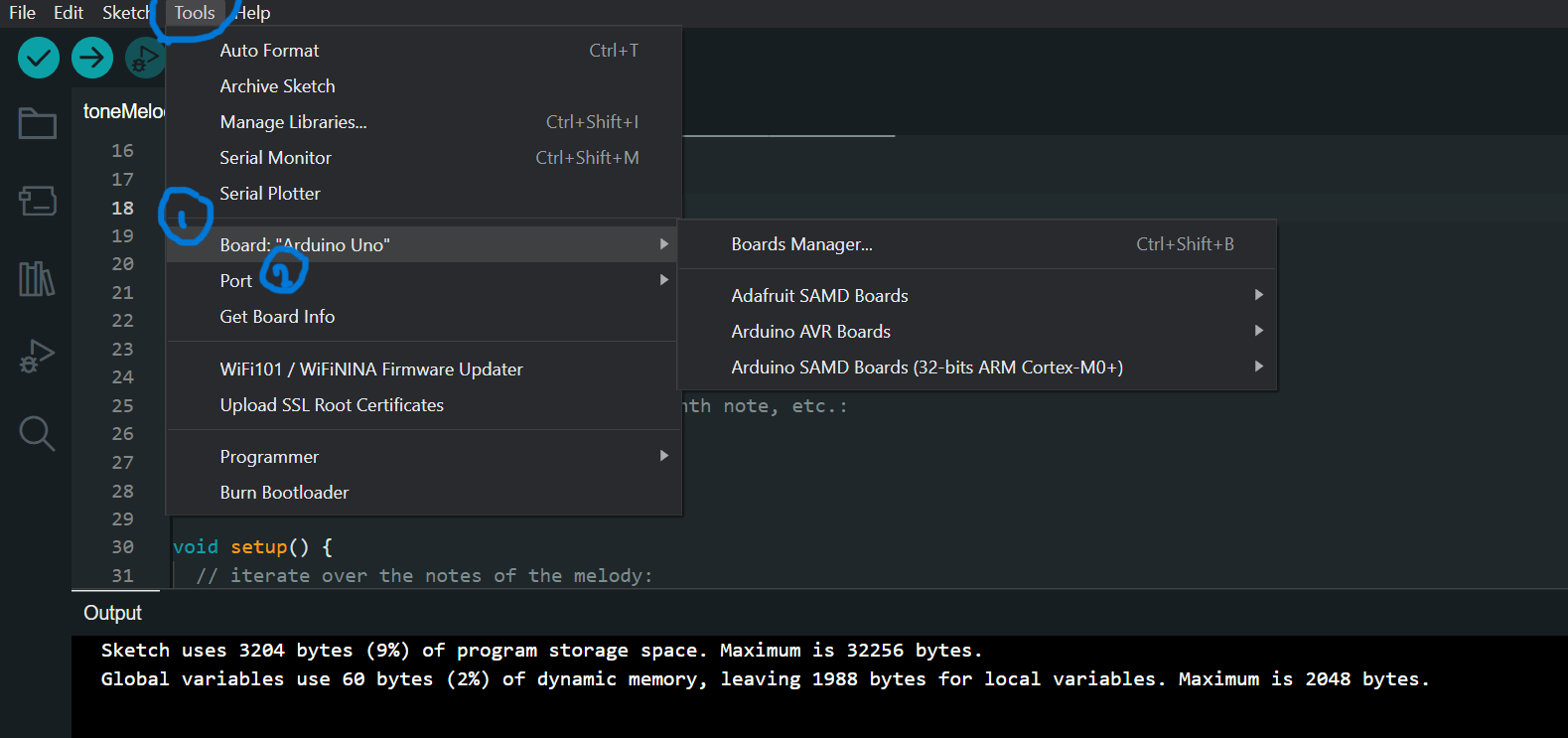
- Write your Arduino code and test it, make sure you select the right port and board, you can get that from Tools tab on top of the page
Code Example
The SETUP function runs once when you press reset
 or power the board

- We use OUTPUT for any object that gives a result
 for example ( LED, Speaker... )
 and INPUT for and object that gives info to the
  computer ( sound Sensor, heat sensor...)

void setup() {
  // initialize digital pin LED_BUILTIN as an output.
  pinMode(LED_BUILTIN, OUTPUT);
}
The LOOP function runs over and over again forever
- We use HIGH for on and LOW for off

void loop() {
  digitalWrite(LED_BUILTIN, HIGH);   // turn the
   LED on (HIGH is the voltage level)
  delay(1000);                       // wait for a
   second
  digitalWrite(LED_BUILTIN, LOW);    // turn the
   LED off by making the voltage LOW
  delay(1000);                       // wait for a
   second
}
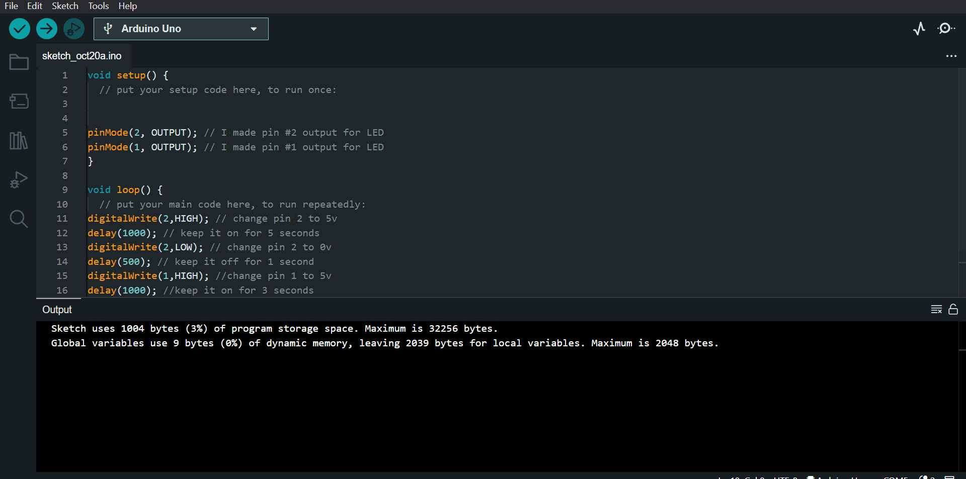
This was my first Arduino circuit prototype, I made two circuits one with two LED lights connected in a series circuit they go on for 5 seconds and off for one second and the other one with one LED light that goes on for 3 seconds and off for one second
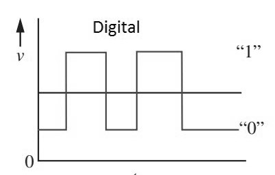
DIGITAL CIRCUITS
digital circuit uses a signal that is used to represent data as a sequence of discrete values, with means you enter a code with an order that is translated as an outcome
Code Example
// constants won't change. They're used here to
 set pin numbers:
const int buttonPin = A1;     // the number of the
 pushbutton pin
const int ledPin =  A2;      // the number of the
 LED pin
// variables will change:
int buttonState = 0;         // variable for
 reading the pushbutton status

void setup() {
  // initialize the LED pin as an output:
  pinMode(ledPin, OUTPUT);
  // initialize the pushbutton pin as an input:
  pinMode(buttonPin, INPUT);
}

void loop() {
  // read the state of the pushbutton value:
  buttonState = digitalRead(buttonPin);

  // check if the pushbutton is pressed. If it is,
   the buttonState is HIGH:
  if (buttonState == LOW) {
    // turn LED on:
    digitalWrite(ledPin, HIGH);
  } else {
    // turn LED off:
    digitalWrite(ledPin, LOW);
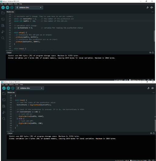
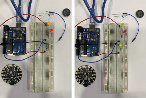
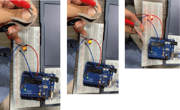
Digital prototype
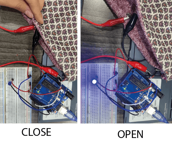
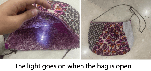
When you open the button the light turns on, when close the button the light turns off
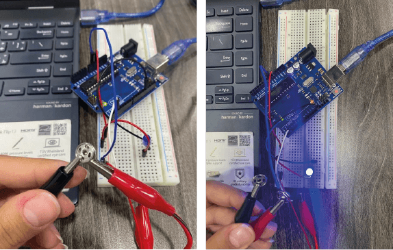
Using the Gemma M0 board
I downloaded the drive for the Gemma M0 using this LINK
Then install SAMD on Arduino using this LINK

In order to make the breadboard prototype real I drew the circuits to make it easier to understand what's going on, used alligator wires, LED light, a clip button and the Gemma board to make sure everything works

When I made sure everything is working I started sewing the board and the light to the bag in the same way they where connected in the prototype it is important to make sure that everything is exactly as they where when you were prototyping
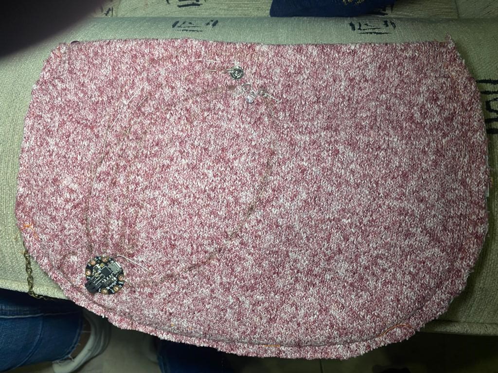
RESULT
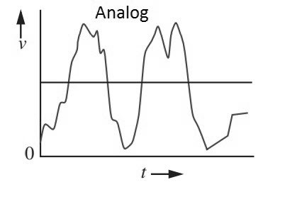
ANALOG CIRCUITS
Analog circuits uses analog data that allows you to control the outcome for example you can say when the pressure is more that 100 turn the light to green or give more light this is a thing that you can not control when using digital circuits
Code Example
// the setup routine runs once when you press reset:
void setup() {
Serial.begin(9600);
pinMode(6,OUTPUT);
}

// the loop routine runs over and over again forever:
void loop() {
  // read the input on analog pin 0:
  int sensorValue = analogRead(A1);
  // print out the value you read:
  Serial.println(sensorValue);
  int ledValue = map(sensorValue,0,420,0,255);
  analogWrite(6, ledValue);
  delay(100);        // delay in between reads for stability
}
Analog prototype
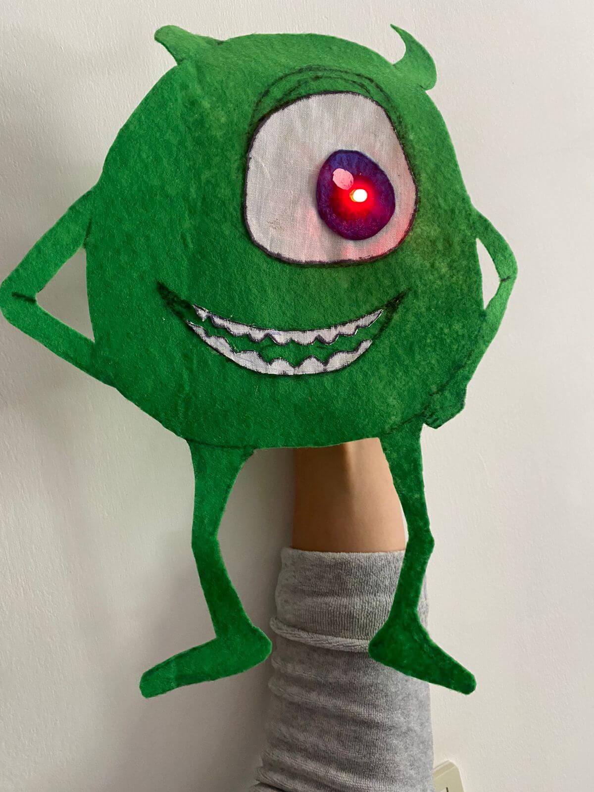
In my circuit I used a code that controls brightness through pressure, the more you press the more light you get
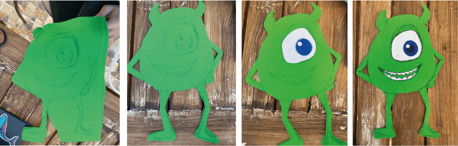
My little sister loves monsters ink movie so I made her a Mike wazowski's doll that lights up when she presses on his belly and changes brightness when she push harder
I started with drawing him on a leftover green felt, cut, then made his eye and teeth using left over white fabric
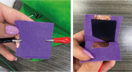
I used velostat fabric to change the resistance added copper tape on each side and covered it with felt like a sandwich forming a pressure sensor
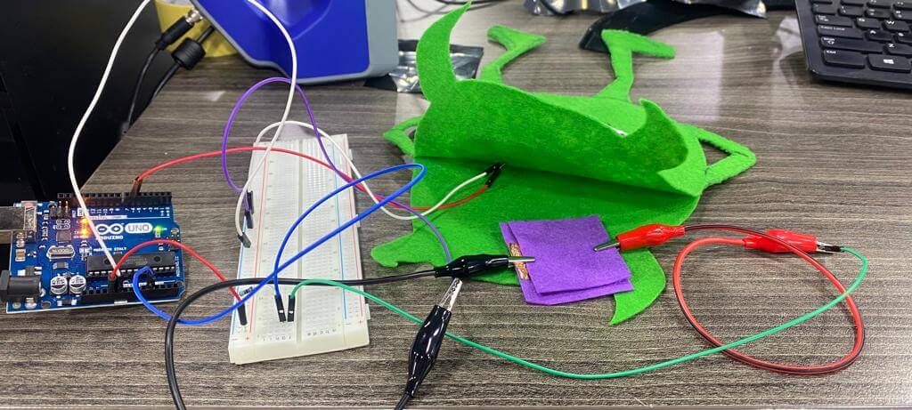
then connected it with the circuit that is made from an LED, Arduino uno with the code in it, jumper wires, 47k resistor and a bread board to test it
I downloaded the same code on a Gemma M0 chip and used a conductive thread to sew the circuit, the LED with the Gemma M0, the velostat sandwich (pressure sensor), the resistor and the battery
BOM
- felt or any left over fabrics
- LED
- Gemma M0 chip
- Conductive thread
- 6V battery
- velostat fabric
- Copper tape
- 47K Ohm resistor
- Arduino program on your computer