8. Wearables

References


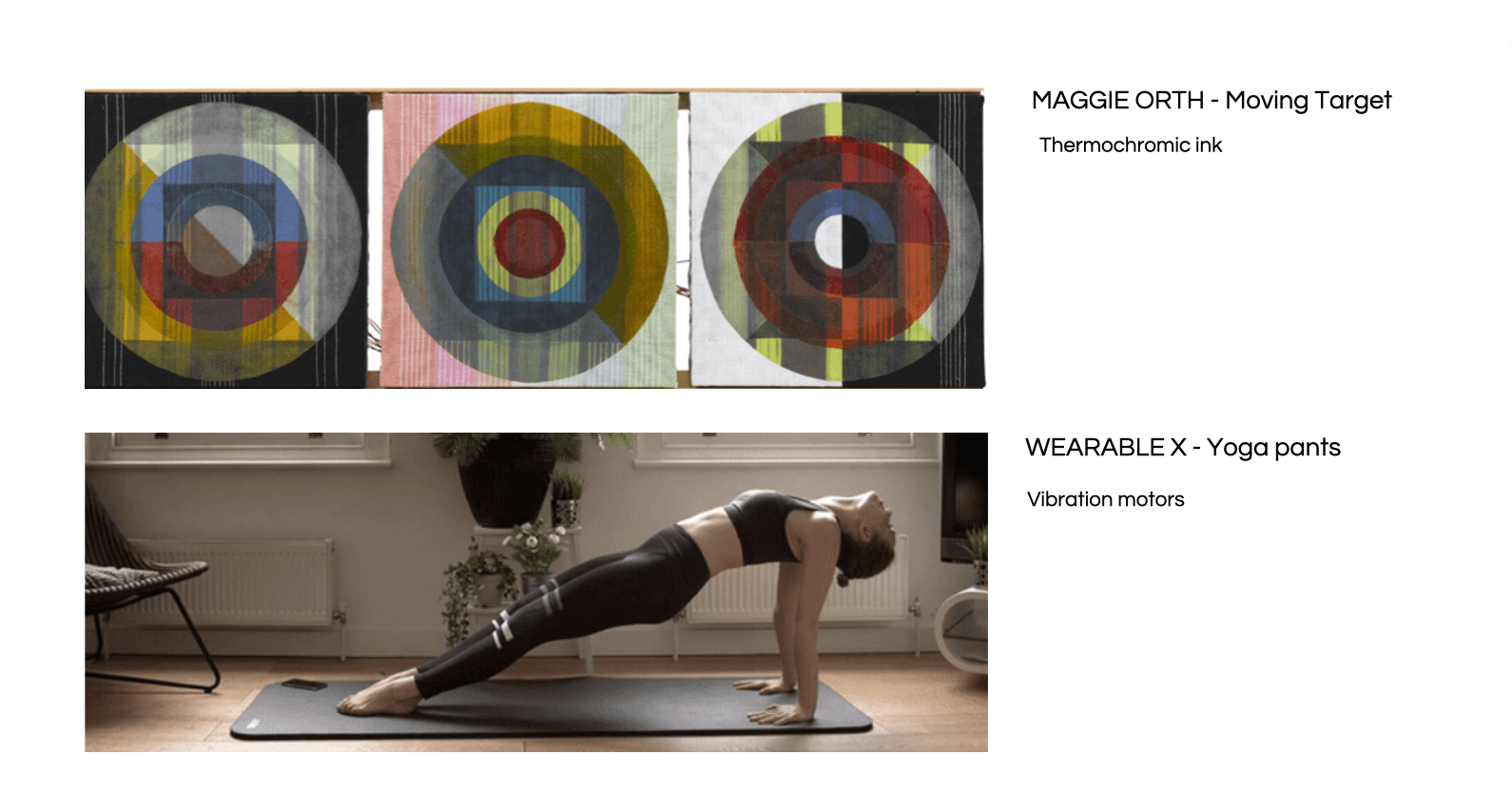
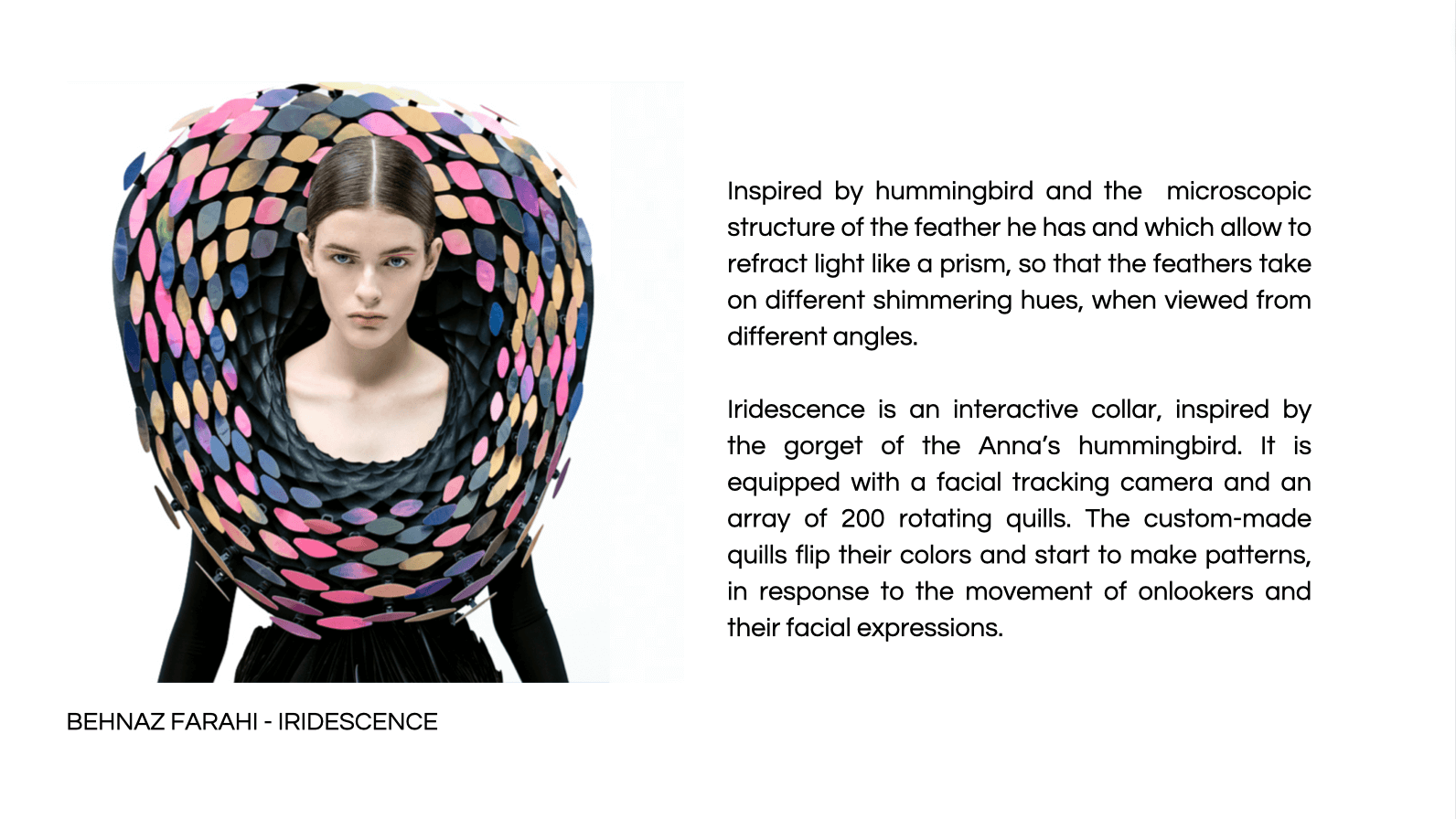
Links of references
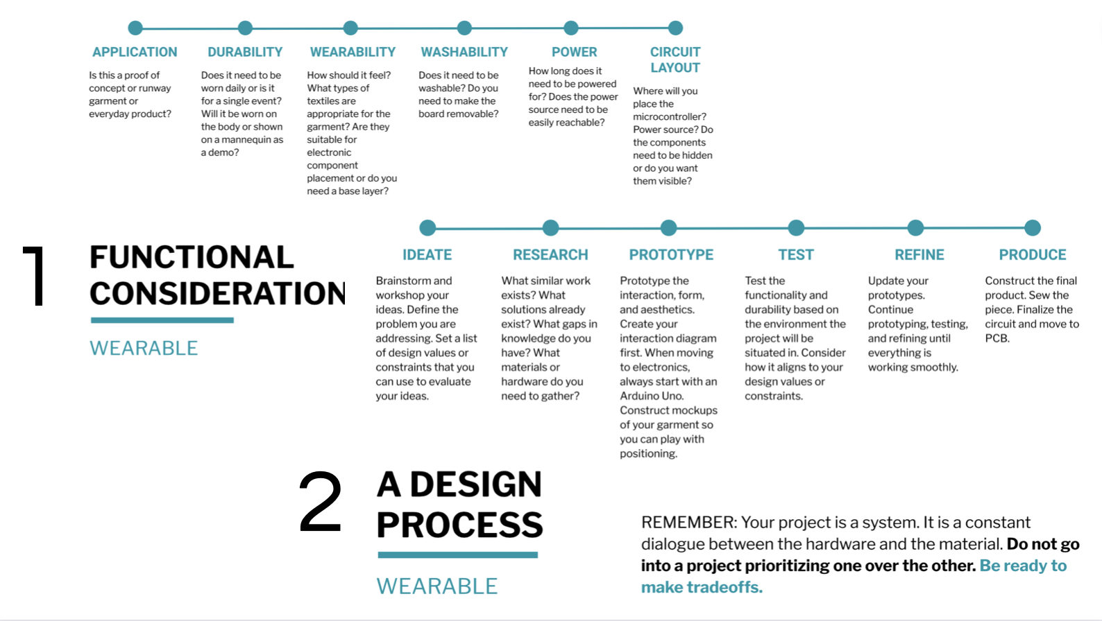
Process by step

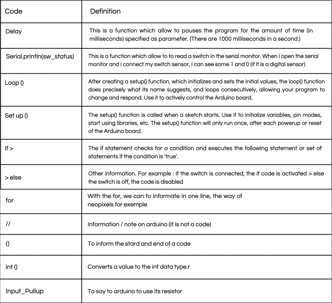
Arduino language
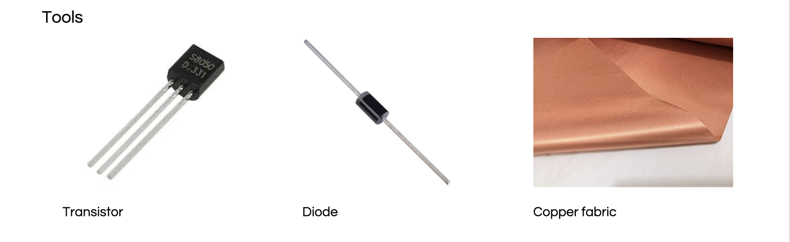
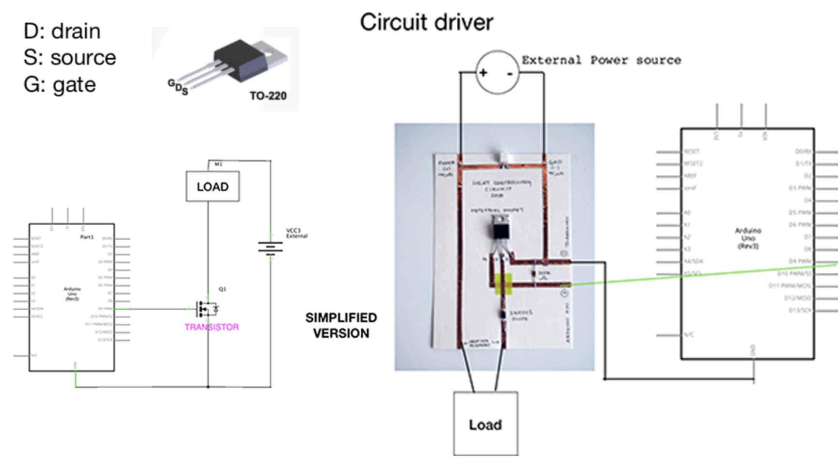
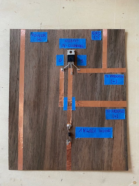
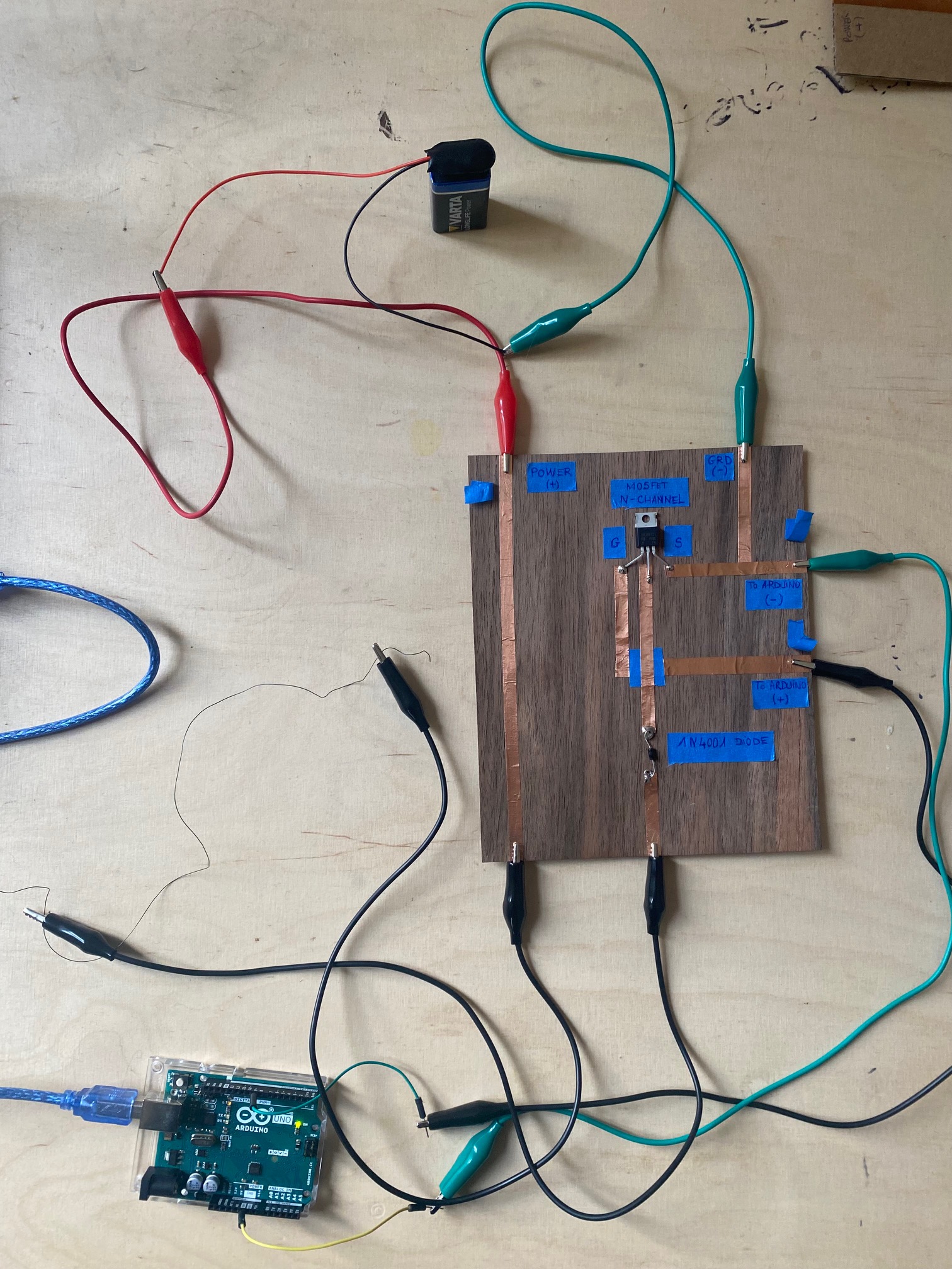
Circuit driver
It is a circuit that allows us to control a Power Load with low Voltage (Arduino) but the Current for the Load in sinked by a difference source.
Experimentations
- MOTION
We was interested by the memory shape alloy called Flexinol with Audrey Kalic. This wire contracts by 10% when in contact with a heat source, here the heat will be brought thanks to the electric circuit and allow us to retract parts of a fabric.
- First step
In order to increase our chances of this working and increase the retraction of the shape memory wire, we heated it for 8 minutes with a 400 degre thermal decar by holding it wrapped around a screw. Then to check that the shape memory worked as we wanted it we plunged it into the cold water so that it resumed its initial form, then into the hot water.

- Second step
After testing the retraction of the wire in hot water, we tried to connect it directly to the driver circuit and to the arduino to see if the electrical circuit generated enough heat to operate the motion. Unfortunately once connected to the battery and the circuit.... nothing happened. After 1 hour trying to understand what the problem was, I came up with the idea to connect it directly with a new battery to see if the problem came from the circuit or the battery. And there, surprise, the wire moves and retracts little by little! Finally...the battery was just empty.
- Third step
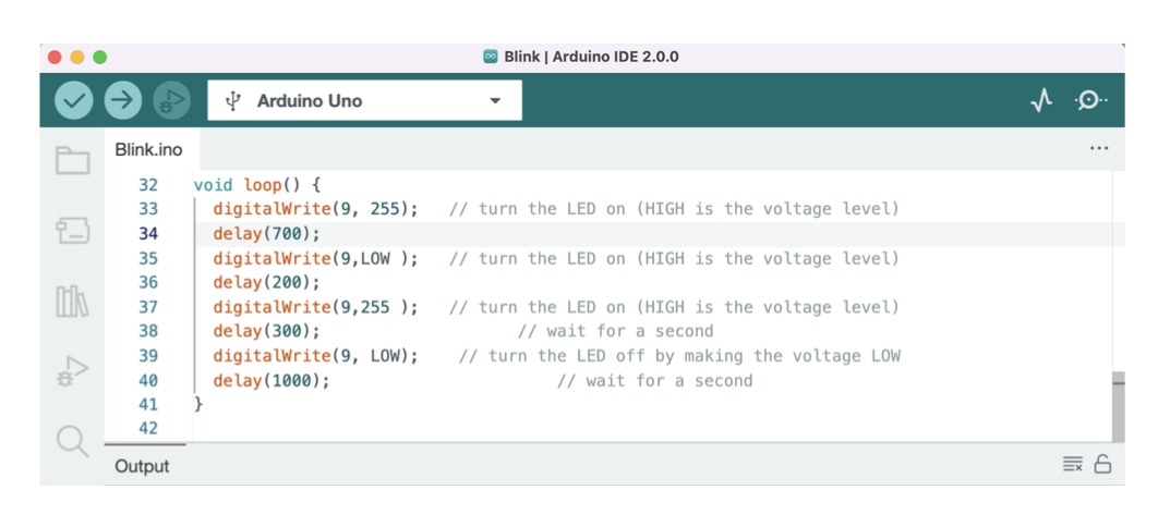
The next step was to incorporate the wire into the fabric, to observe how the fabric would behave with the retraction of the wire. I wanted at the same time to manage the contraction of the wire thanks to Arduino. I had the idea of trying to program the movement of the wire so that it corresponds to those of a heartbeat, that is to say 2 beats per second, then a second without heartbeat. To do this I used the Blink program in the examples of the Arduino software, which I modified in order to obtain a contraction rate that suited me.
Original code:
/*
  Blink

  Turns an LED on for one second, then off for one second, repeatedly.

  Most Arduinos have an on-board LED you can control. On the UNO, MEGA and ZERO
  it is attached to digital pin 13, on MKR1000 on pin 6. LED_BUILTIN is set to
  the correct LED pin independent of which board is used.
  If you want to know what pin the on-board LED is connected to on your Arduino
  model, check the Technical Specs of your board at:
  https://www.arduino.cc/en/Main/Products

  modified 8 May 2014
  by Scott Fitzgerald
  modified 2 Sep 2016
  by Arturo Guadalupi
  modified 8 Sep 2016
  by Colby Newman

  This example code is in the public domain.

  https://www.arduino.cc/en/Tutorial/BuiltInExamples/Blink
*/

// the setup function runs once when you press reset or power the board
void setup() {
  // initialize digital pin LED_BUILTIN as an output.
  pinMode(LED_BUILTIN, OUTPUT);
}

// the loop function runs over and over again forever
void loop() {
  digitalWrite(LED_BUILTIN, HIGH);   // turn the LED on (HIGH is the voltage level)
  delay(1000);                       // wait for a second
  digitalWrite(LED_BUILTIN, LOW);    // turn the LED off by making the voltage LOW
  delay(1000);                       // wait for a second
}
Modification:
- Fourth step
We then tried to heat another wire by tightening it much more thanks to a nut, we wanted to see if it changed anything, if the wire was retracting much more or not at all. The result was rather positive since once put in the hot water, the wire twisted on it much more than previously and very quickly.

- Fifth step
Then we wanted to incorporate this motion system has a textile by creating a flower that closes on itself. For this we cut a flower shape into a fairly fluid cotton fabric and then we made a hand stitch to fix the shape memory thread along the petals. I then ran the threads under the fabric to hide them and be able to connect them easily to the electrical circuit.
- LEDS
Analog/digital sensor.
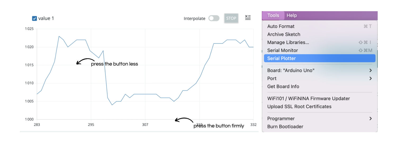
We did some neopixels experimentations thanks to the thursday class, the first was to control the lighting of the neopixel thanks to an analog sensor. We used arduino to control the on and the off of the button but also the intensity of the light or the speed at which the led will blink. Then with the function serial plotter we can see the intensity variation on a graph. On this video for exemple the led blink faster when I press lower on the button which are velostat, and it blink lower when I press the button strongly. On the graph we can see that the curve is low when I press the analog sensor hard, and up when I press little.
How to control the switch?
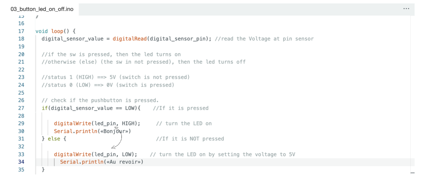
This program is a good example to understand how to indicate to the led when it should light up. In this program, the led turns on when the button is pressed, and it turns off when it is not pressed.
If we want to reverse the process, we just have to reverse « HIGH » and « LOW ». Then, when the button is not pressed, the led will turn on by setting the voltage to 5V.
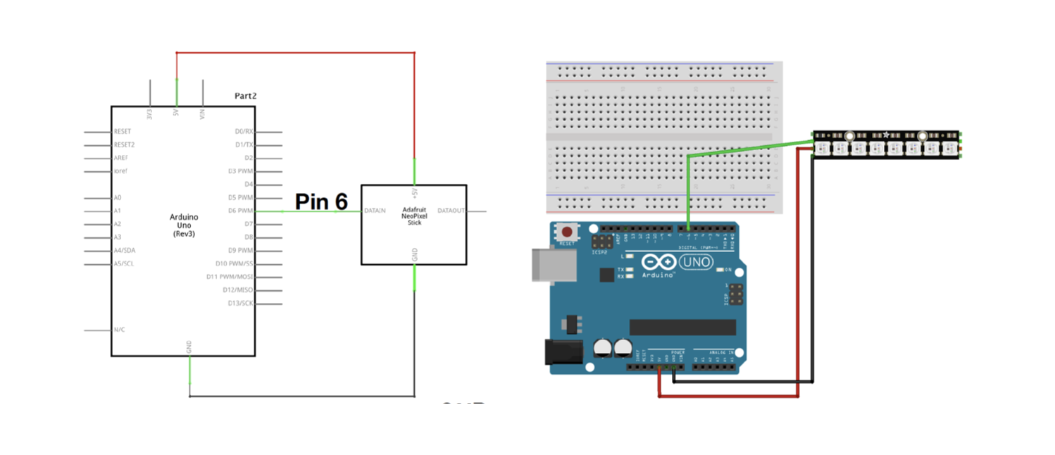
- NEOPIXELS.
First I had to install a neopixel library and add the Adafruit library
What is a library? It is a set of function that are ready to be used.
But they are not installed in Arduino IDE by default.
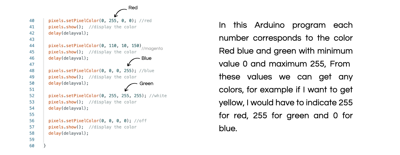
I learned to control the color of the led by indicating the RGB values of the colors I want to get.
- Define a loop.
This program allows to create a color sequence, which will occur on each led, one after the other, i+1 tells it that once the loop is complete, it is the turn of the next led to light.
In this situation the led n1 will light in magenta, then in blue, then it will turn off, and it will be the turn of the second led to produce this loop and so on.
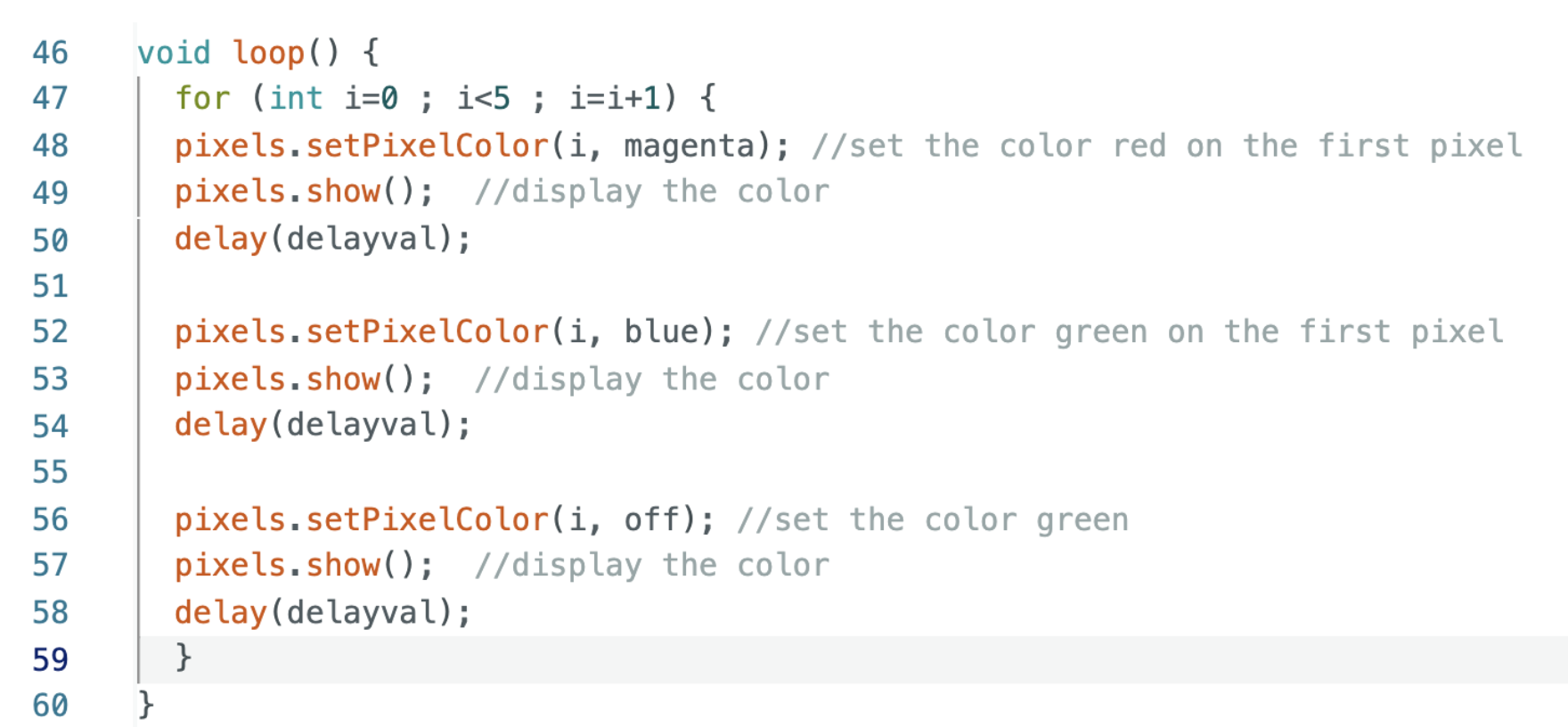
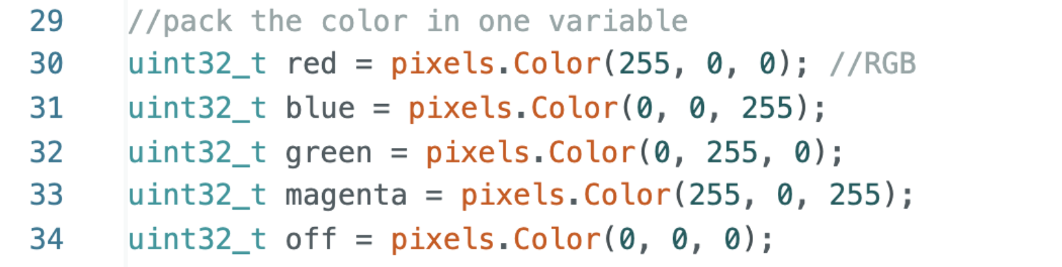
The colors are predefined upstream in the program thanks to the RGB values. In this way, when indicating (i, magenta), the program will already know that magenta is defined by the values 255 red and 255 blue
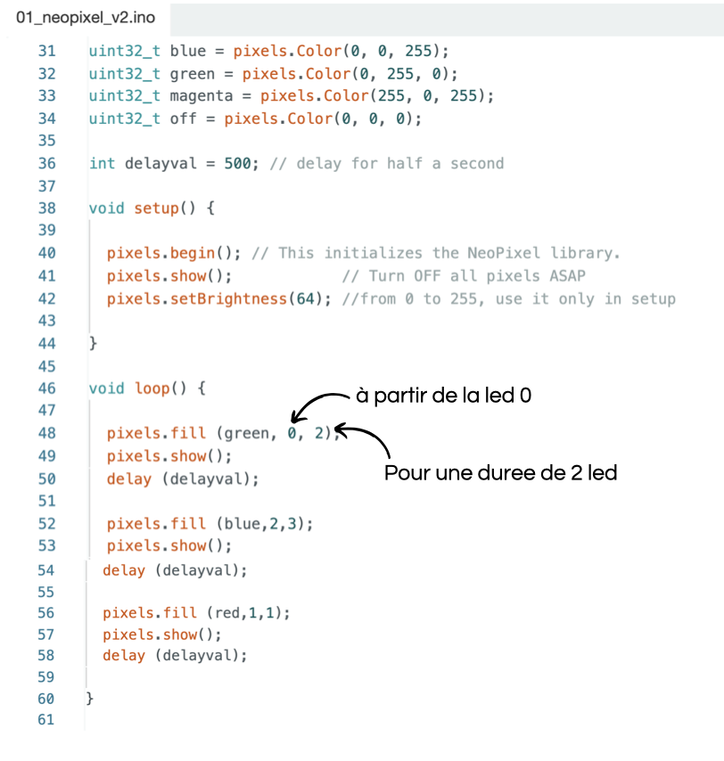
In this other program, the color is also defined upstream, then we have the possibility to create loops by ordering some LEDs to light with some color one after the other.
First we indicate the color, then from which led we want the led to light, and finally we indicate for how many led we want to get the color.
For example, in this situation the led 0 and 1 will light green, then the 2-3-4 in blue, and finally the led number 1 will light red.
- SPEAKERS.
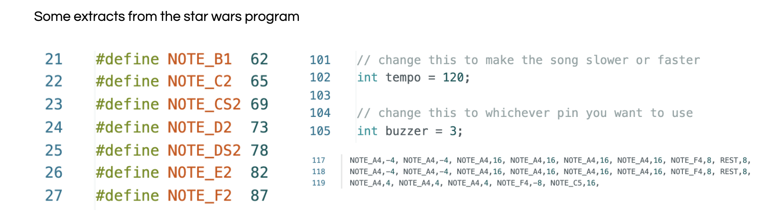
My firt experimentation was with diane speakers, I already knew it was working but I wanted to try a sound arduino program, so I used the Star Wars program with Laura Guillerm, I watched the structure of the program and I was trying to understand how it was working.
Each note is determined by a variable but also each pose, each breath and the duration of each of its notes. That’s a lot of information all of a sudden to write myself coding one of my favorite songs...after all, watchinng is good too from time to time.