13. Skin Electronics
In the same way that the wearables industry is integrating fashion practices in their development, skin electronic allows for new partnerships between the biotech/tech companies and skin professionals such as makeup artists, prosthesis experts and tattooists in order to embrace the idea of human-device symbiosis. FX e-makeup made use of special effects makeup for hiding electronic components that sense facial muscle movements, acting as a second skin.
References
- KINISI - KATIA VEGA. Interactive skin.
- A combined effort from engineers at the school's Soft Machines Lab and Morphing Matter Lab, ElectroDermis is a new way to apply electronics to the skin, whether it be for medical, fitness or lifestyle purposes.
- Chromoskin. Color-changing makeup.
- Electronic tatoos.
Ressources:Katia Vega website
Research
This week, we learned how to use an ATtiny to can create different micro electronic circuit wearables.
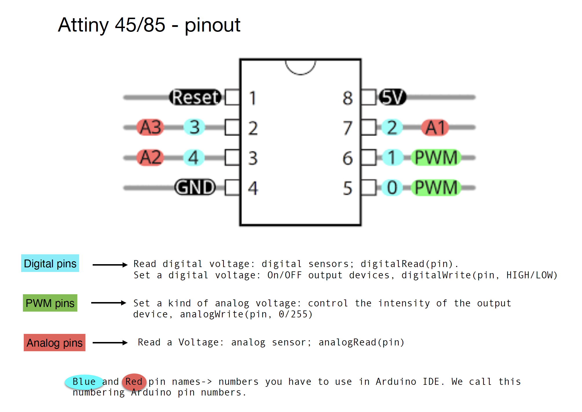
To start it is important to understand the correspondence of each branch of the attiny. I use an attiny 85 for my experiments.
Material I need:
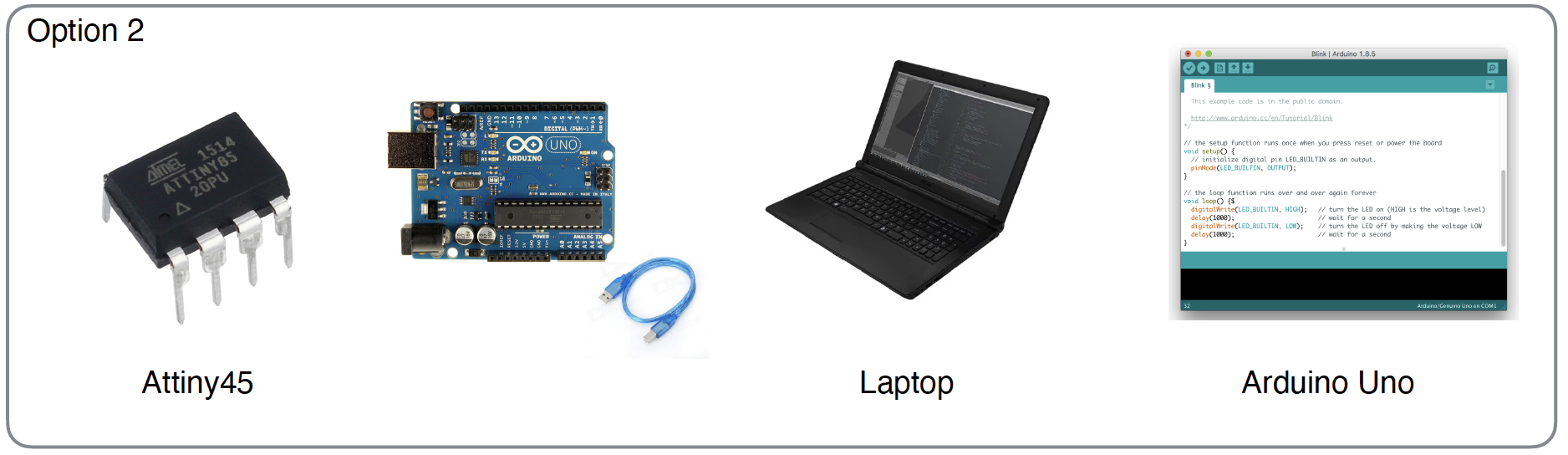
We have to go through arduino beforehand and then transfer the arduino code to the attiny. However if we had a tiny AVR programer we could directly code the attiny.
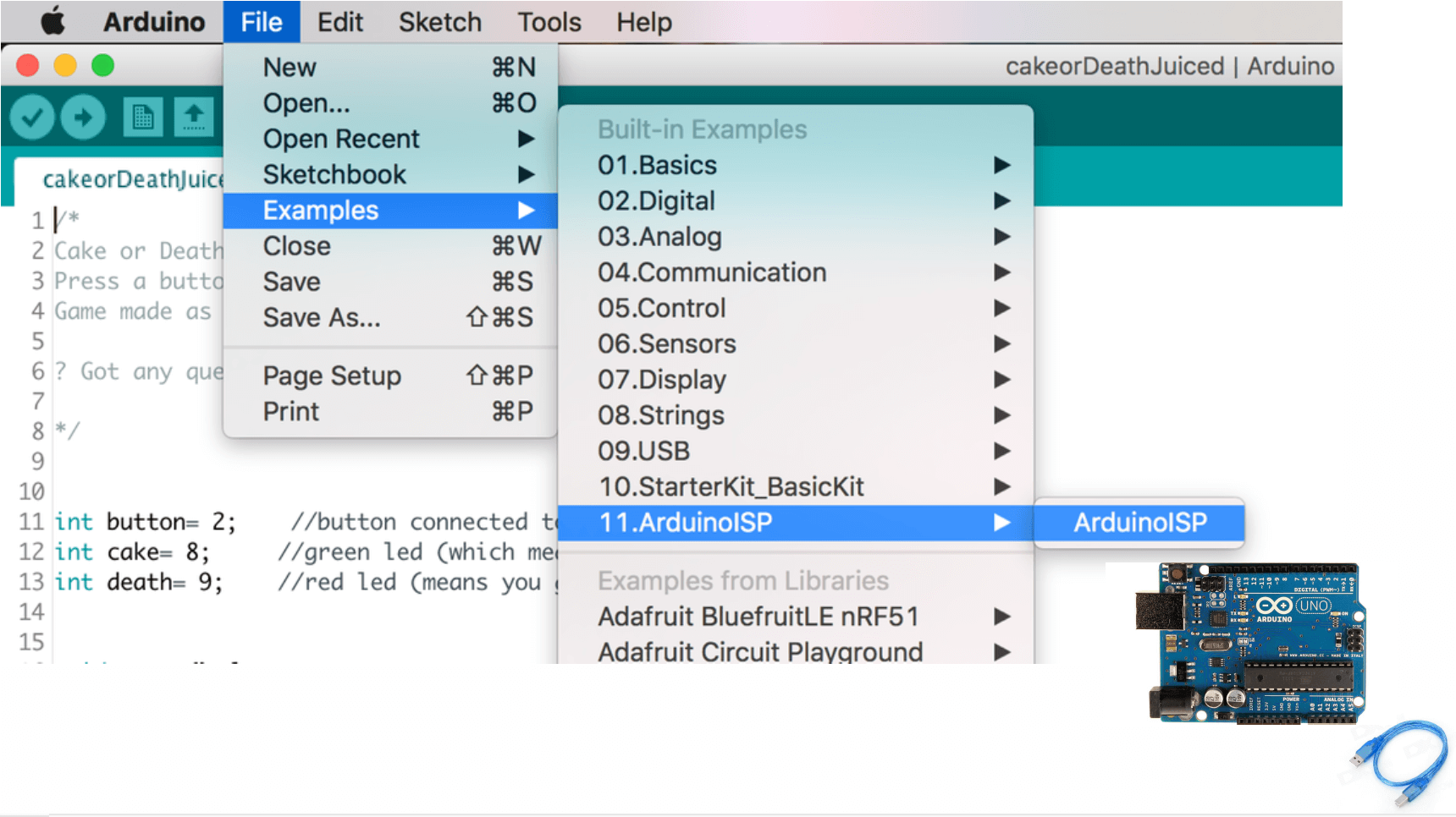
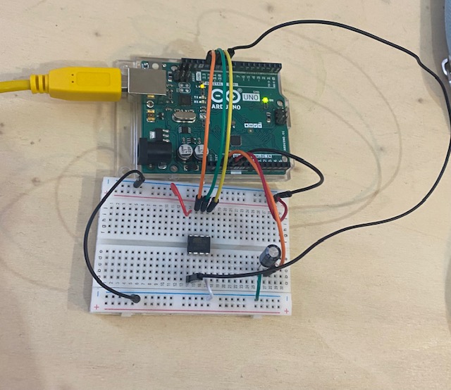
- Upload the right code (ArduinoISP) in your Arduino Uno
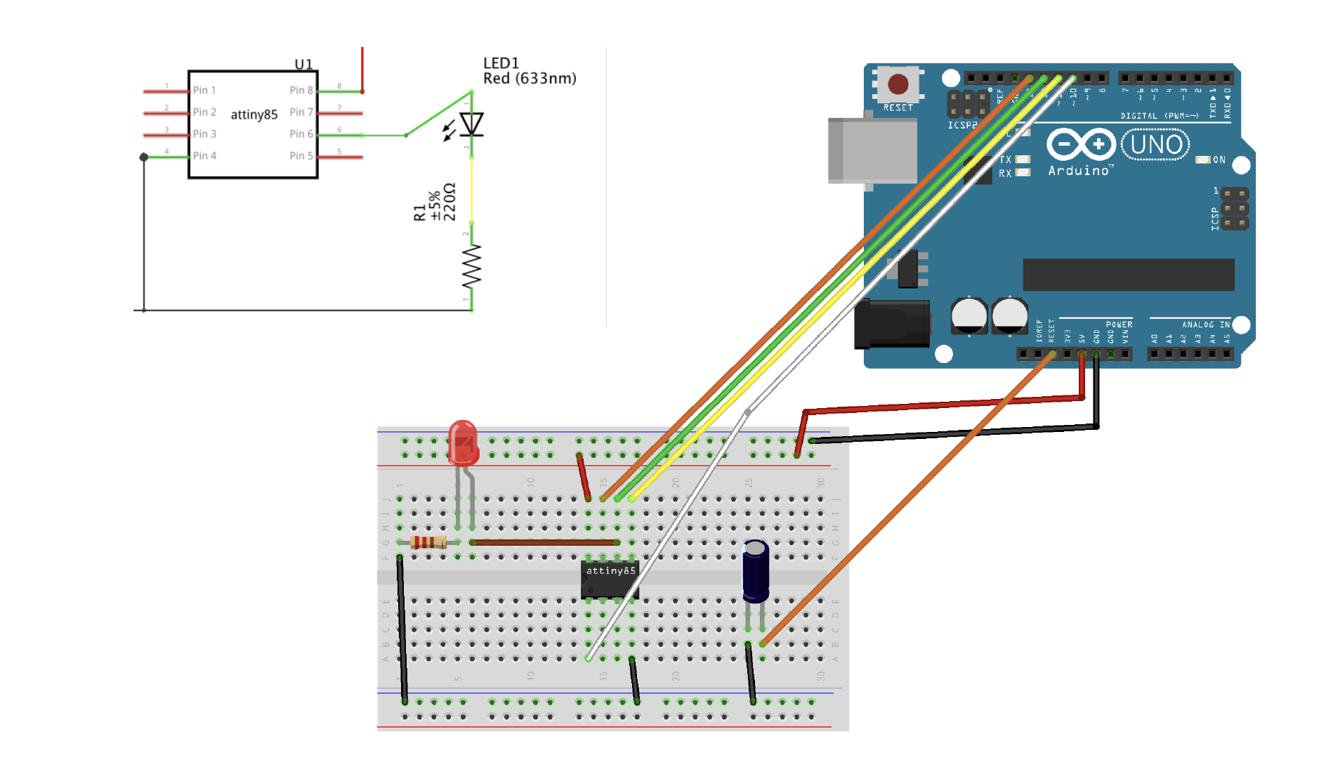
- Make this circuit:
- In Arduino IDE:


- Upload the code to the Attiny

Attiny Led code
/* Emma Pareschi, Nov 2019
 *
 *  the led connected to pin 1. it blinks
*/

int led_pin = 1;  //pin of the Led

void setup() {
  // put your setup code here, to run once:
  pinMode(led_pin, OUTPUT);   // set the pin 1 as OUTPUT

}

void loop() {
  // put your main code here, to run repeatedly:
  digitalWrite(led_pin, HIGH);      //turn the Led ON
  delay(1000);                //wait
  digitalWrite(led_pin, LOW);       //turn the Led OFF
  delay(1000);                //wait
}
- Test it!
- Try another circuit
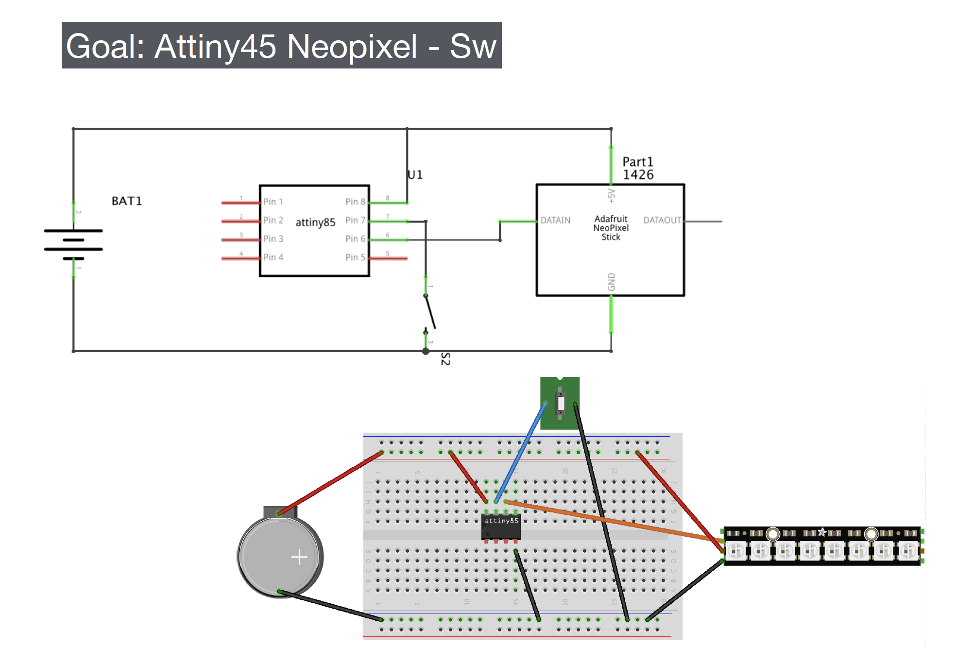
- Upload the code to the Attiny

Attiny neopixel Wipe code:
#include <Adafruit_NeoPixel.h>
// A basic everyday NeoPixel strip test program.

// NEOPIXEL BEST PRACTICES for most reliable operation:
// - Add 1000 uF CAPACITOR between NeoPixel strip's + and - connections.
// - MINIMIZE WIRING LENGTH between microcontroller board and first pixel.
// - NeoPixel strip's DATA-IN should pass through a 300-500 OHM RESISTOR.
// - AVOID connecting NeoPixels on a LIVE CIRCUIT. If you must, ALWAYS
//   connect GROUND (-) first, then +, then data.
// - When using a 3.3V microcontroller with a 5V-powered NeoPixel strip,
//   a LOGIC-LEVEL CONVERTER on the data line is STRONGLY RECOMMENDED.
// (Skipping these may work OK on your workbench but can fail in the field)

// Which pin on the Arduino is connected to the NeoPixels?
// On a Trinket or Gemma we suggest changing this to 1:
#define LED_PIN    1

// How many NeoPixels are attached to the Arduino?
#define LED_COUNT 8

// Declare our NeoPixel strip object:
Adafruit_NeoPixel strip(LED_COUNT, LED_PIN, NEO_GRB + NEO_KHZ800);
// Argument 1 = Number of pixels in NeoPixel strip
// Argument 2 = Arduino pin number (most are valid)
// Argument 3 = Pixel type flags, add together as needed:
//   NEO_KHZ800  800 KHz bitstream (most NeoPixel products w/WS2812 LEDs)
//   NEO_KHZ400  400 KHz (classic 'v1' (not v2) FLORA pixels, WS2811 drivers)
//   NEO_GRB     Pixels are wired for GRB bitstream (most NeoPixel products)
//   NEO_RGB     Pixels are wired for RGB bitstream (v1 FLORA pixels, not v2)
//   NEO_RGBW    Pixels are wired for RGBW bitstream (NeoPixel RGBW products)

uint32_t off = strip.Color(0, 0, 0);

int sw_pin = 2;
int sw_status = 0;


// setup() function -- runs once at startup --------------------------------

void setup() {

  strip.begin();           // INITIALIZE NeoPixel strip object (REQUIRED)
  strip.show();            // Turn OFF all pixels ASAP
  strip.setBrightness(50); // Set BRIGHTNESS to about 1/5 (max = 255)

  pinMode(sw_pin, INPUT_PULLUP);

}


// loop() function -- runs repeatedly as long as board is on ---------------

void loop() {

   sw_status = digitalRead(sw_pin);

   if (sw_status == 0){
      colorWipe(strip.Color(255,   0,   0), 50); // Red
      strip.fill(off, 0, 10);
      strip.show();  //display the color
    }
}

// Fill strip pixels one after another with a color. Strip is NOT cleared
// first; anything there will be covered pixel by pixel. Pass in color
// (as a single 'packed' 32-bit value, which you can get by calling
// strip.Color(red, green, blue) as shown in the loop() function above),
// and a delay time (in milliseconds) between pixels.
void colorWipe(uint32_t color, int wait) {
  for(int i=0; i<strip.numPixels(); i++) { // For each pixel in strip...
    strip.setPixelColor(i, color);         //  Set pixel's color (in RAM)
    strip.show();                          //  Update strip to match
    delay(wait);                           //  Pause for a moment
  }
}
- Test it!!
- Electronic tatoo
The material I need for the tattoo:

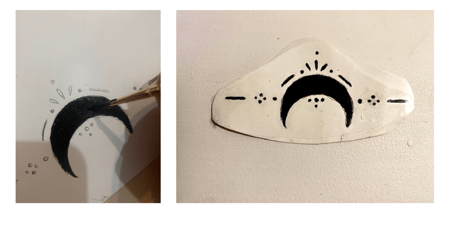
The design:

Result of the tattoo:
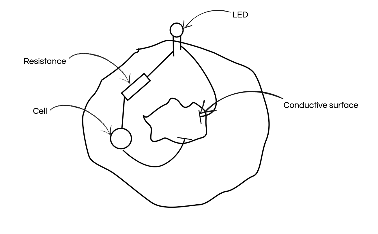
The purpose of this tattoo will be to light LEDs incorporated into a garment, or has an accessory, here I use a hair scrunchie as an accessory. The electrical circuit will then be hidden in the inside of the scrunchie. The circuit will be complete only when it is in contact with the tattoo placed on the wrist. Here is a diagram to see a little clearer.
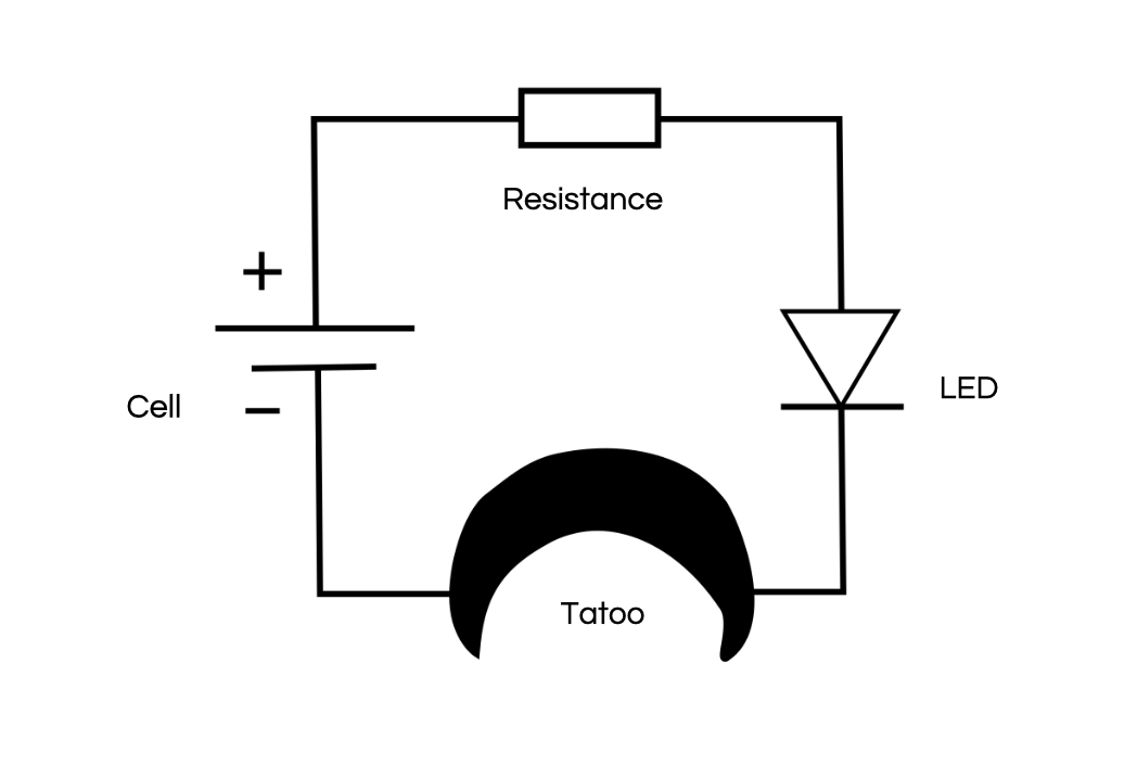
Circuit diagram integrated in the scrunchie:
Once the circuit was integrated with the scrunchie, I did a first test without the tattoo to see if my circuit was working.
Unfortunately, the tattoo test was inconclusive... I first did a test by transferring the tattoo to a flesh-coloured tights...but it didn’t work, so I did another test by putting the circuit directly in contact with the tattoo but...it didn’t work either. I think it’s due to the transfer of the paper that puts a light layer of glue on the tattoo.