8. Wearables
 Learning outcomes
- Research skills: the participant has acquired knowledge through references and Concept development
- Design skills: the participant has learnt by programming a microcontroller, design a circuit and schematic
- Fabrication skills: the participant acquired skills necessary to integrate inputs and outputs in a microcontroller wearable project
- Process skills: Anyone can go through the process, understand it and reproduce it
- Final outcome: Assembled project, functioning and complete
- Originality: Has the design been thought through and elaborated?
Student checklist
- Document the concept, sketches, references also to artistic and scientific publications
- Create a swatch/sample using an ATTiny/Arduino/Adafruit with one input and one output, using hard-soft connection solutions and battery
-
Create 2 actuator swatches and test them with the Arduino or ATTiny, choosing from examples such as:
- motors / mini vibration
- leds / neopixels
- flip dot / electromagnet
- heat pad / with thermochromic coating
- speaker / mp3 player
- SMA (shape memory alloy)
- Learn how to program an Arduino/ATTiny/Adrafruit, documenting your process, the libraries added, power requirements and source code
-
Document the schematic and circuit
- Upload a small video of your object working
- Integrate it to a project (extra credit)
Research
About Actuator
In general, an actuator is a device or mechanism within a control system that receives commands and generates force or motion based on those commands. In other words, it's a device that converts one form of energy into another. For example, motors that convert electrical signals into mechanical motion.
- DC motor, Servo motor, Stepper motor
- Shape memory, Artificial muscle, Solenoid, Vibration motor, flip dots
Furthermore, the definition at the Fabricademy includes Visual (LED) and Sound (Speaker).
- LED, Thermochroic ink
- Sound (speaker)
Inspiration
After taking the class, I first thought that Fabric Speaker was interesting. I've used a variety of speakers from large to small, and I've also used them at Fabrication works. However, when I saw the Fabric Speakers, I started thinking again about the principle behind how sound comes from speakers.
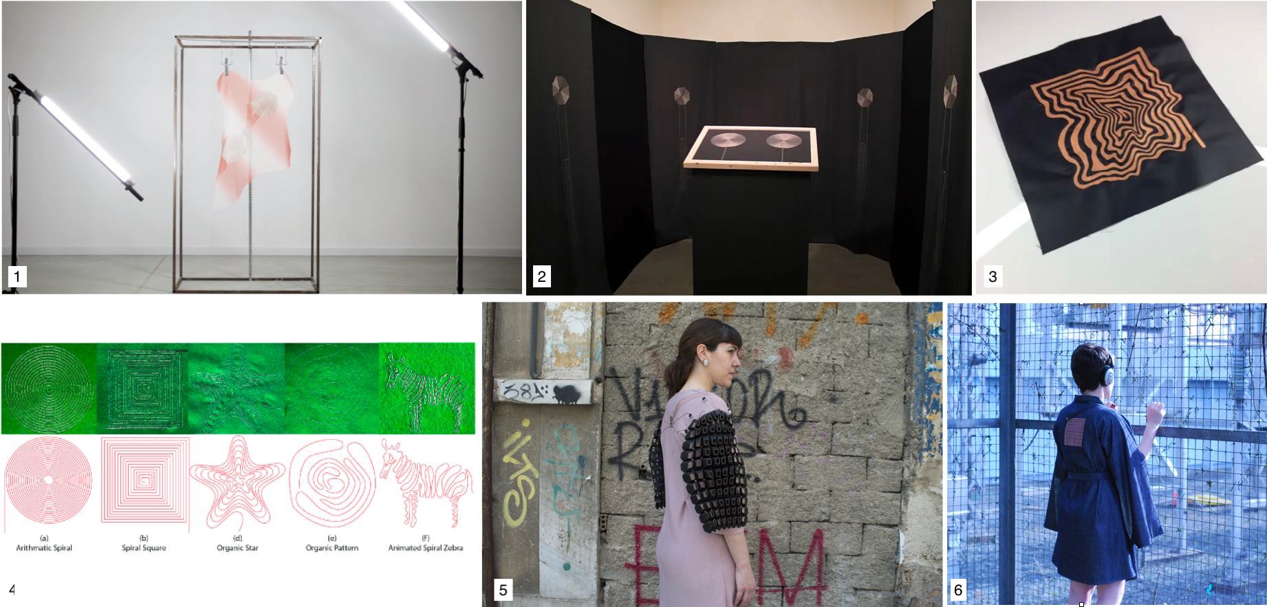
1: Folding Frequencies, 2: Ryth Kesselring, 3: Fabric Speaker, 4: research, 5: Fractal Antennae, 6: The Culture
Unlike regular speakers, there were many conceptual works of art that were integrated with fabrics. Research 4 included an example of using Fabric Speaker as Haptic device. For example, while playing a video game, you can feel the vibrations from a fabric speaker attached to the back of your clothes. 5 was also introduced in class. Using SMA, the sleeves of the clothes move as if they were breathing.
References & Inspiration
- Fabric speaker swatch example
- Embroidered Fabric Speaker
- Make magazine Volume 84 P.82 Soft Speakers
- Flapping wings
- Fabric Flipdot with H-Bridge
Tools
Process and workflow
Fabric Speaker
To make fabric speakers, I checked the conductive thread list I made at the E-textile week. Then tried to sew swirl pattern using the conductive thread 2 and 4. The reason for choosing them was to check the difference in resistance and had a large stock of those yarns. (It's okay if I fail)
material

1) Conductive Thread 1 : stainless steel 0.27Ω/cm
2) Conductive Thread 2 : stainless steel 0.92Ω/cm
3) Conductive Thread 3 : stainless steel 0.92Ω/cm
4) Conductive Thread 4 : polyester, nylon 10Ω/cm
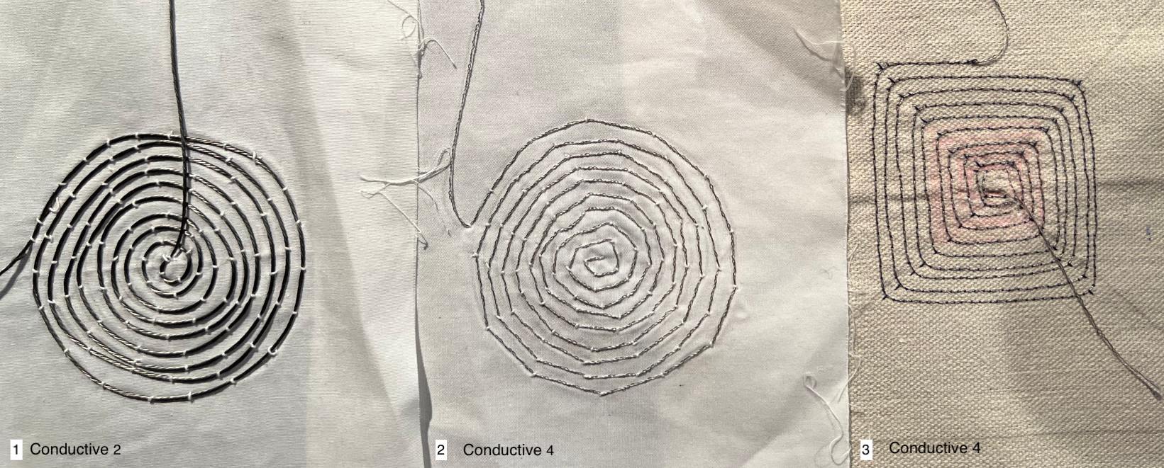
1. Conductive Thread2 stainless 0,93Ω、Cotton cloth, manual stich
2. Conductive Thread4 polyester, nylon 10Ω/cm 、Cotton cloth, manual stich
3. Conductive Thread4 polyester, nylon 10Ω/cm 、hemp(Harder than the above cotton), sewing machine
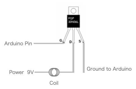
Circuit
I referred to the following circuit of the class. I used Arduino UNO and the MOSFET 2SK2231.

Code
/*******************************************
 *  Week8 Fabric Speaker
 ******************************************/

const int spPin = 5; //Arduino UNO

void setup() {
pinMode(spPin,OUTPUT);
}

void loop() {
//hz1000();
toneOut();

}

void hz1000(){
  digitalWrite(spPin, HIGH);
  delayMicroseconds(500);
  digitalWrite(spPin, LOW);
  delayMicroseconds(500);

}
void toneOut(){
//tone(pin, frequency, duration Usec)
  tone(spPin,261.626,1000000000);  //c4
  delay(1000);
  noTone(spPin);
  delay(50);
  tone(spPin,261.626,1000000000);  //c4
  delay(1000);
  tone(spPin,391.995,1000000000);  //G4
  delay(1000);
  noTone(spPin);
  delay(50);
  tone(spPin,391.995,1000000000);  //G4
  delay(1000);
  tone(spPin,440.000,1000000000);  //A4
  delay(1000);
  noTone(spPin);
  delay(50);
  tone(spPin,440.000,1000000000);  //A4
  delay(1000);
  tone(spPin,391.995,1000000000);  //G4
  delay(2000);
  tone(spPin,349.228,1000000000);  //F4
  delay(1000);
  noTone(spPin);
  delay(50);
  tone(spPin,349.228,1000000000);  //F4
  delay(1000);
  tone(spPin,329.628,1000000000);  //E4
  delay(1000);
  noTone(spPin);
  delay(50);
  tone(spPin,329.628,1000000000);  //E4
  delay(1000);
  tone(spPin,293.665,1000000000);  //D4
  delay(1000);
  noTone(spPin);
  delay(50);
  tone(spPin,293.665,1000000000);  //D4
  delay(1000);
  tone(spPin,261.626,1000000000);  //c4
  delay(2000);
  noTone(spPin);
  delay(200);
  }
Result
Below is a video of Conductive Thread 2. Conductive Thread4 did not produce any audible level of sound. The cause seems to be a combination of high resistance, small speaker size, magnet power, cloth, etc.
- Small magnet x1, no enclosure
In order to increase the volume, I tried adding an embroidery hoop to add tension (thank you, Rico), using a cup as a casing, and changing the number of magnets.
The magnet has a noticeable effect, but the casing and tension also seem to change.

- Small neodymium magnet x3, embroidery hoop, cup enclosure. Even if you place a small magnet on top, you will still hear the sound.
Flip
material
- Enamelled copper wire: Diameter 0.1mm
- Make a coil by wrapping 80 rounds around the pen.
- Sand the edges with sandpaper
- magnet
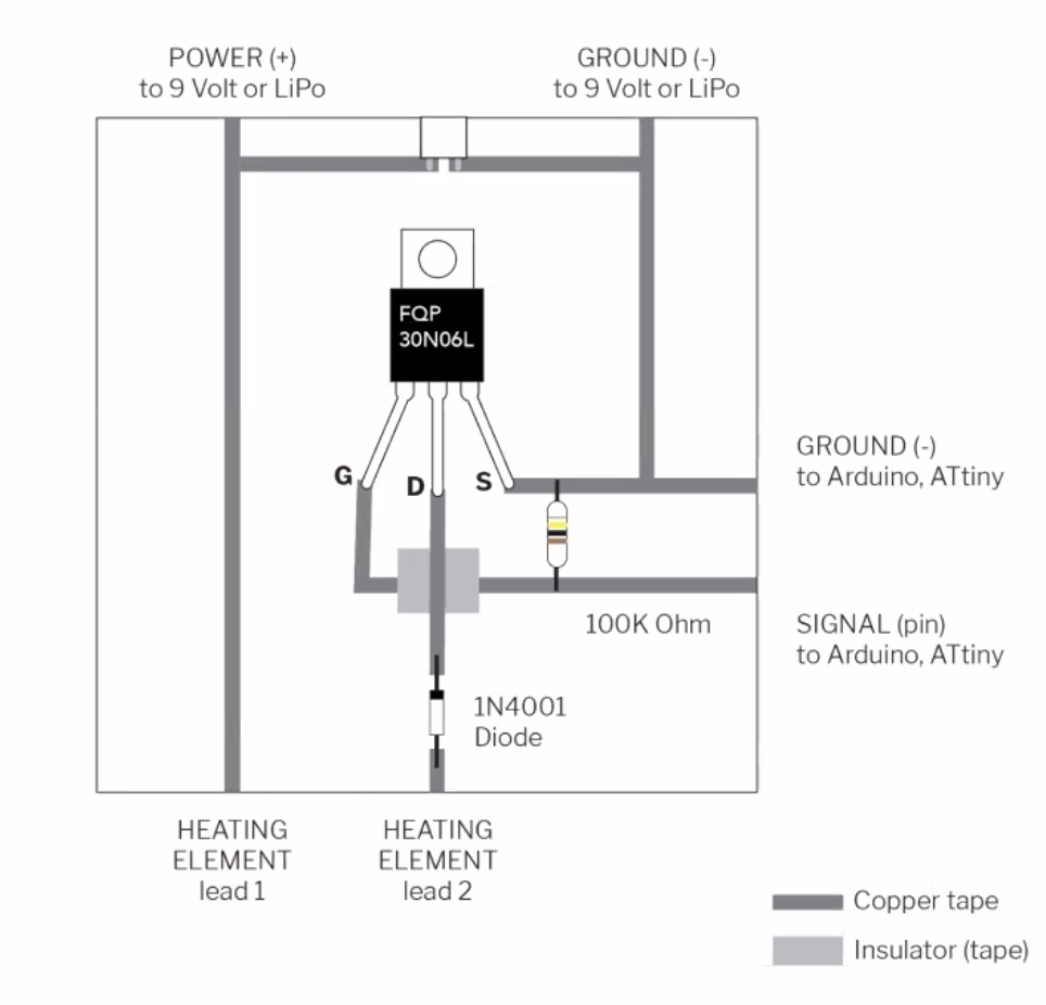
Circuit
Code
/************************************
    Week8  Flip
 *********************************/

const int Pin = 5;  //Uno

void setup() {
  pinMode(Pin, OUTPUT);
}

void loop() {
  digitalWrite(Pin, HIGH);
  delay(1000);
  digitalWrite(Pin, LOW);
  delay(1000);

}
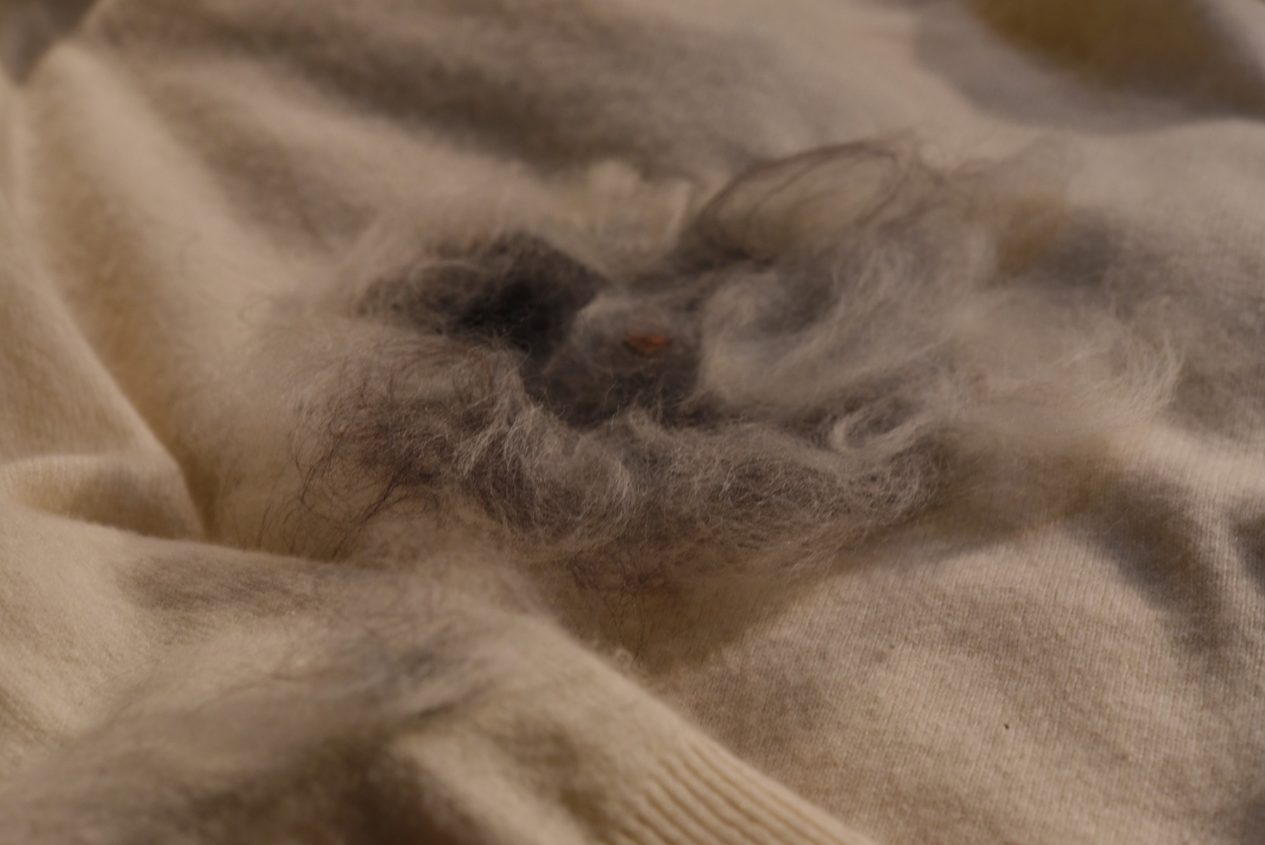
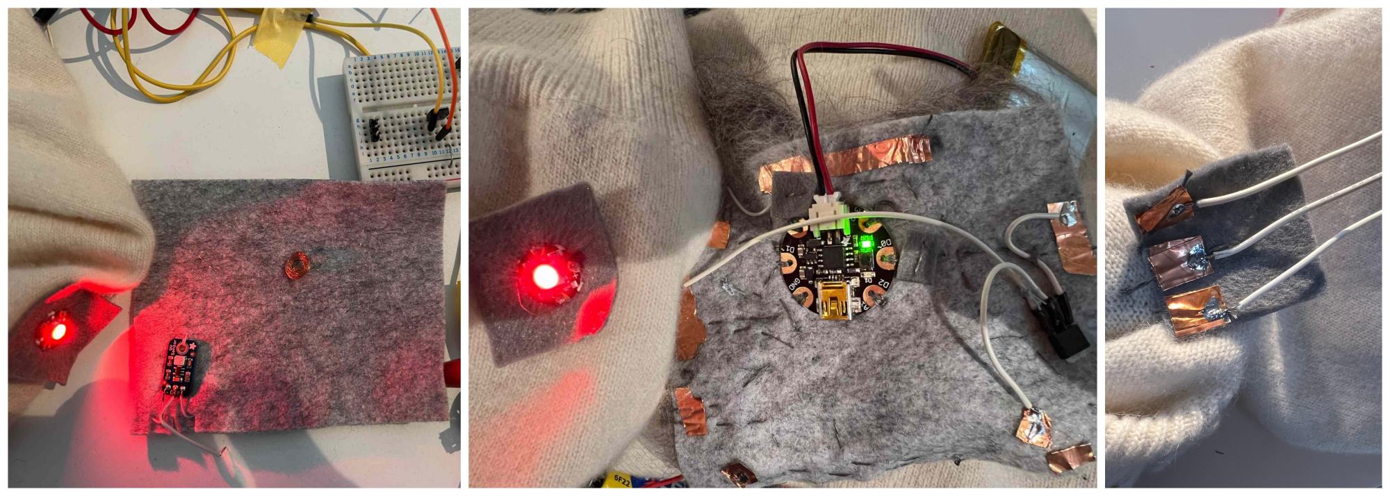
Result: bouncing hairball
Wireless LED
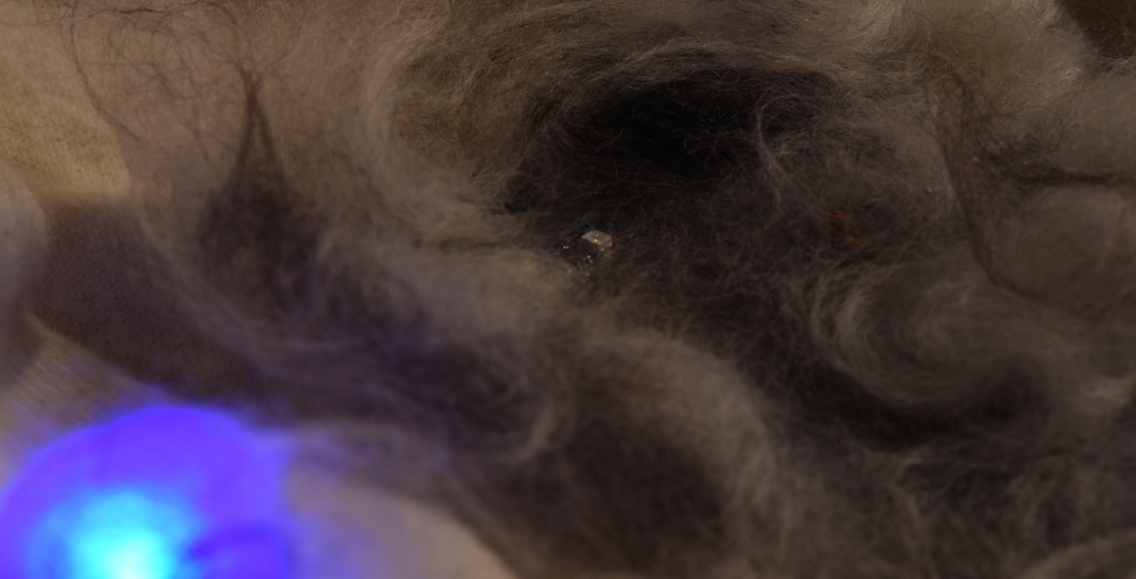
My local instructer, Rico teached me the Wireless LED. This LED requires no wiring and is charged by a power supply coil unit like this one. This is a mechanism often seen in electric toothbrushes.
When I brought this LED close to my coil, it was a faint but the LED was lit. Interesting!
SMA
material
- SparkFun SMA 0.30mm = 0.012 inch
- SparkFun SNA 0.13mm =0.005 inch
Circuit
Code
/**********************************************
  week8 SMA Trial
     SMA1   0.3mm diameter
     SMA2   0.13mm
 ***********************************************/

const int smaPin = 5;
int maxVal=255;

void setup() {
//  Serial.begin(9600);
}

void loop() {
  analogWrite(smaPin, maxVal);
  // analogWrite(smaPin, random(150,maxVal));

 delay(1000);
 analogWrite(smaPin, 0);
 delay(random(800,1000));

}
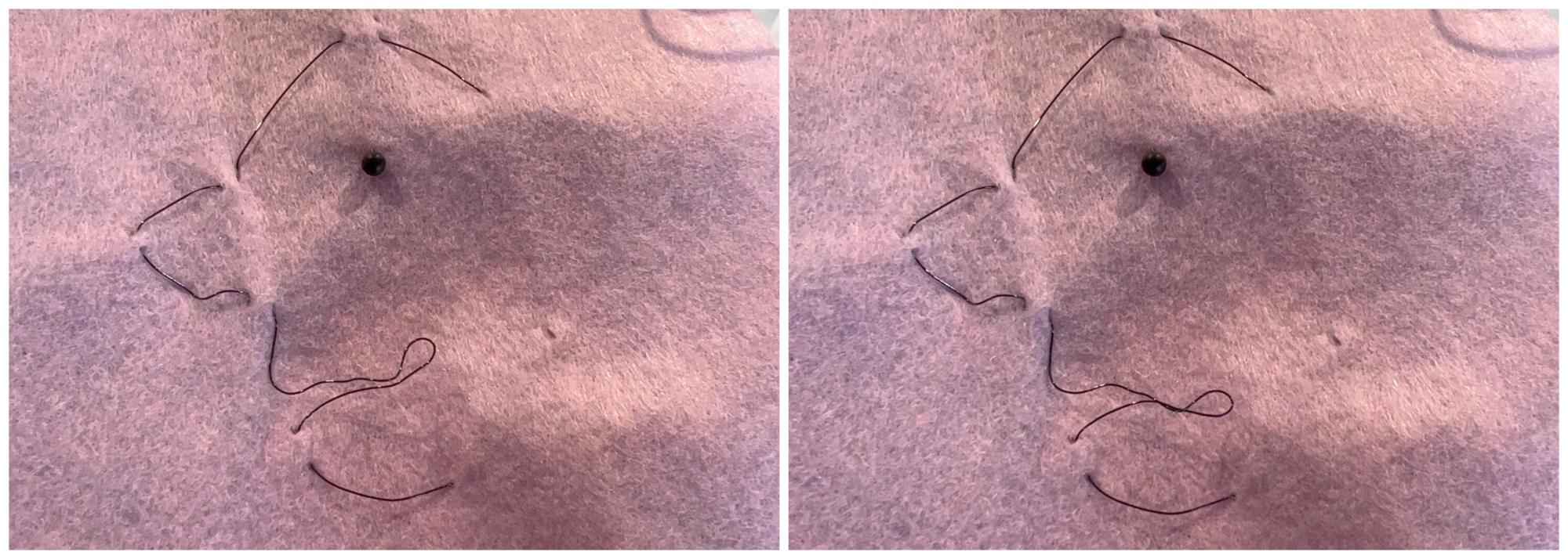
Result: Dancing Line Drawing
The movement was faint, but I loved the faint organic movement with no motor sound.
- SparkFun SNA 0.13mm (0.005 inch)
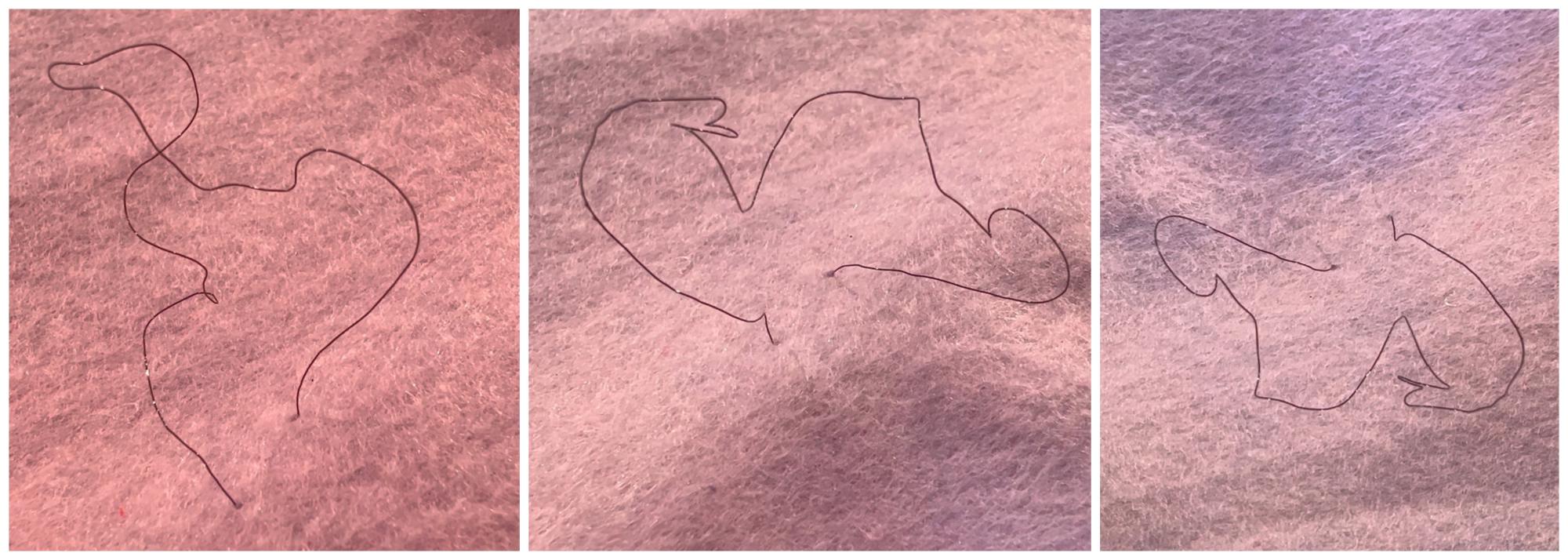
- SparkFun SMA 0.30mm (0.012inch): Changes in facial expression by SMA. I also wanted to move the eyebrows.
ATtiny85 @Gemma
I've built the ATtiny44 board several times at FabAcademy and used it in my Final Project. This time I didn't have an ATtiny microcontroller on hand, so I decided to use Adafruit's Gemma, although it's old product. The Gemma is a microcomputer board that uses Attiny85 and can sew. It also has a Lipo Battery connector.
Pinouts

Programming
There is a good instruction at adafruit's page. Since the Gemma has built-in USB bootloader, it's convenient.
Point:
-
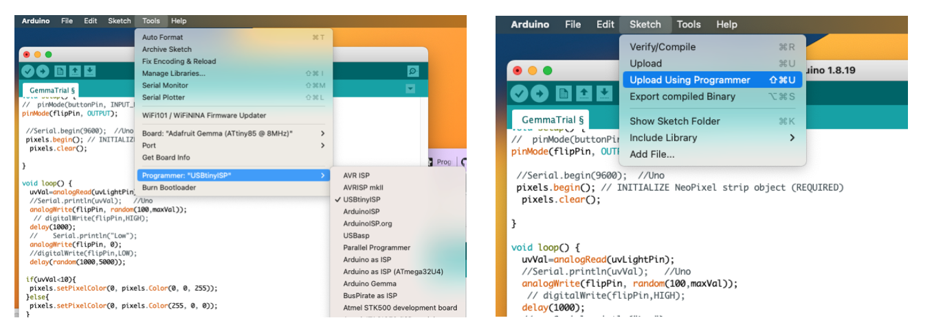
Gemma has some versions. So check here to set up Arduino IDE properly. In case of my black Gemma board, select "USBtinyISP" instead of "Arduino Gemma" programmer.
-
There is no need to select a port in the Arduino IDE. (Gemma's port is not displayed)
- To enter bootloader mode, connect USB cable, press little button on the bord.Don't press-and-hold the button, be sure to press-and-release! Red LED flashes. Then in the Arduino IDE "Sketch > Upload Using Programmer"
- Use USB2.0 or hub to make it recognize by USB port
- Serial monitor cannot be used
Integration idea
- A design that visualizes heartbeats using Flip experiment
- I didn't use a heart rate sensor this time. Just simulate the movement.
- As an input, a UV sensor that I have never used before, but seems like it would be good to use in a wearable device.
- When UV level is low, the LED on the sleeve glows blue
- When UV level is high, the LED on the sleeve glows red. A kind of alert as UV can be bad for our skin.
It's an unrelated combination...UV & heart beat so far... Hmm. . . But in terms of project management, I have to do my homework.

Code
/**********************************************
 Week8 Gemma
 ***********************************************/
#include <Adafruit_NeoPixel.h>
//const int flipPin = 9;    //UNO
const int flipPin = 0;    //Gemma  OK
const int uvLightPin = A1;  //Gemma A1 check


//#define PIN   5 //UNO
#define PIN   1 //GEMMA

#define NUMPIXELS  1// Number of NeoPixel
Adafruit_NeoPixel pixels(NUMPIXELS, PIN, NEO_GRB + NEO_KHZ800);

int uvVal=0;
int maxVal=255;

void setup() {
  pinMode(flipPin, OUTPUT);
 //Serial.begin(9600);  //Uno
  pixels.begin(); // INITIALIZE NeoPixel strip object (REQUIRED)
  pixels.clear();

}

void loop() {
  uvVal=analogRead(uvLightPin);
  //Serial.println(uvVal);   //Uno
  analogWrite(flipPin, random(100,maxVal));
   // digitalWrite(flipPin,HIGH);
  delay(1000);
  //    Serial.println("Low");
  analogWrite(flipPin, 0);
  //digitalWrite(flipPin,LOW);
  delay(random(500,2000));

 if(uvVal<10){
  pixels.setPixelColor(0, pixels.Color(0, 0, 255));
 }else{
  pixels.setPixelColor(0, pixels.Color(255, 0, 0));
 }
  pixels.show();   // Send the updated pixel colors to the hardware

}
Input/Output
- UV light sensor
- It uses a UV photo diode, which can detect the 240-370nm range of light (which covers UVB and most of UVA spectrum). Read the value by Analogue read port.
- LED: Flora RGB Smart NeoPixe
- Flip
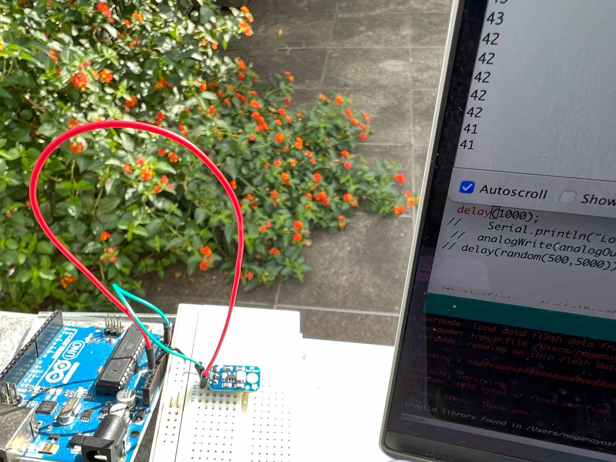
First I checked the UV sensor with Arduino UNO and serial monitor. Because the GEMMA can't use serial monitor, need some display device to check the standard UV value.
The value was almost single digit indoors and about 40 under today's sunlight. So I decided the red and blue LED thresholds to 10 and programmed it. I covered the sensor with mohair and was able to obtain UV values without any problems.
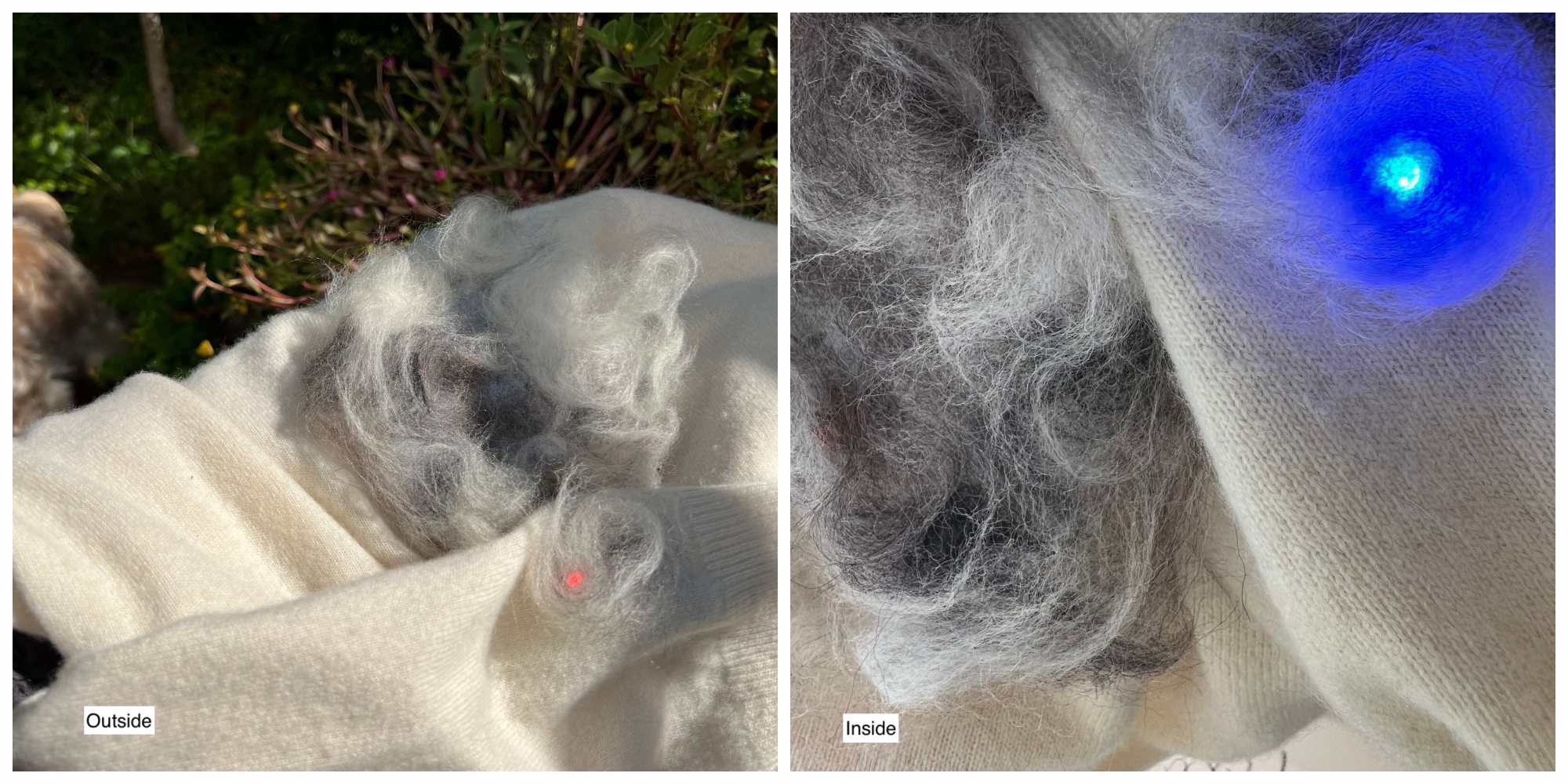
Result: My secret heartbeat and UV care
Integration was more difficult than expected. Even though it was working properly, when I went outside, the solder had come off before I knew it. The tester sound was my friend.