Process 2 (After Midterm Review)
Seed Wing
3D modeling
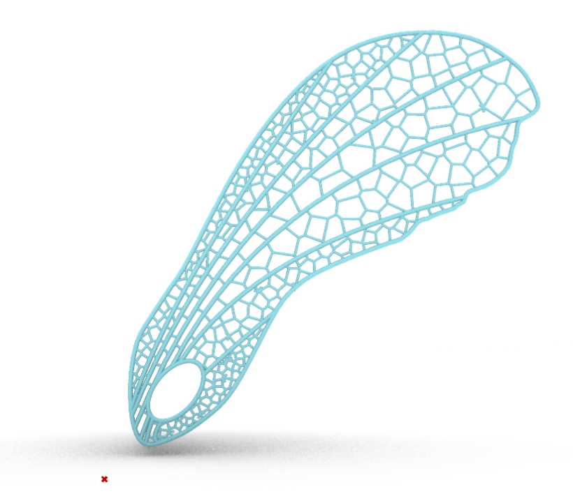
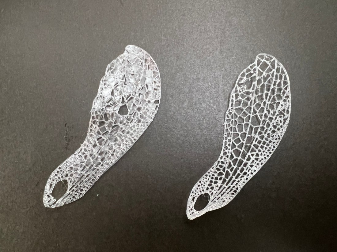
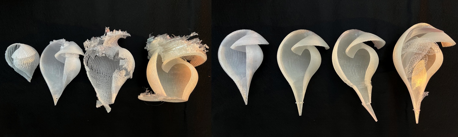
I tried adding a dragonfly wing-like pattern using Voronoi to improve the design.
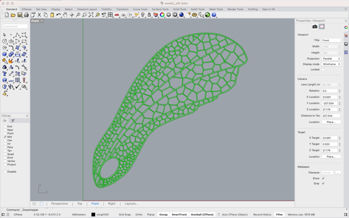

Create the base wing line on Rhinoceros.

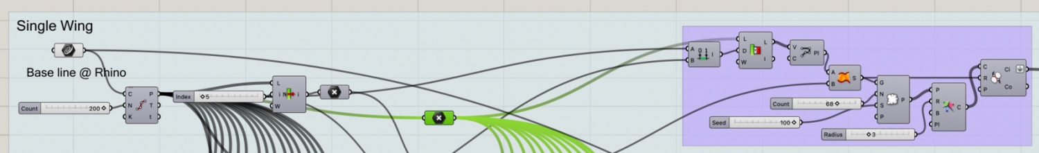
In Grasshopper, select the curve and divide it vertically into 7 areas. Below is the code to generate a Voronoi pattern in one area.
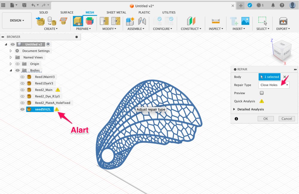
Before 3D printing, load the STL model into Fusion 360 and check that there are no holes or other problems in the mesh. I tried repairing it with Grasshopper, but it often didn't repair it completely, so I decided to use Fusion360.
At Fusion360, select "Mesh" tab > select "INSERT" > "Insert Mesh" > select STL file.
As shown below, when I loaded this SeedWing model, an alert was displayed. Therefore, I selected "Repair" tool and "Close Holes" type as follows to repair it. Then saved the result as a new STL model.
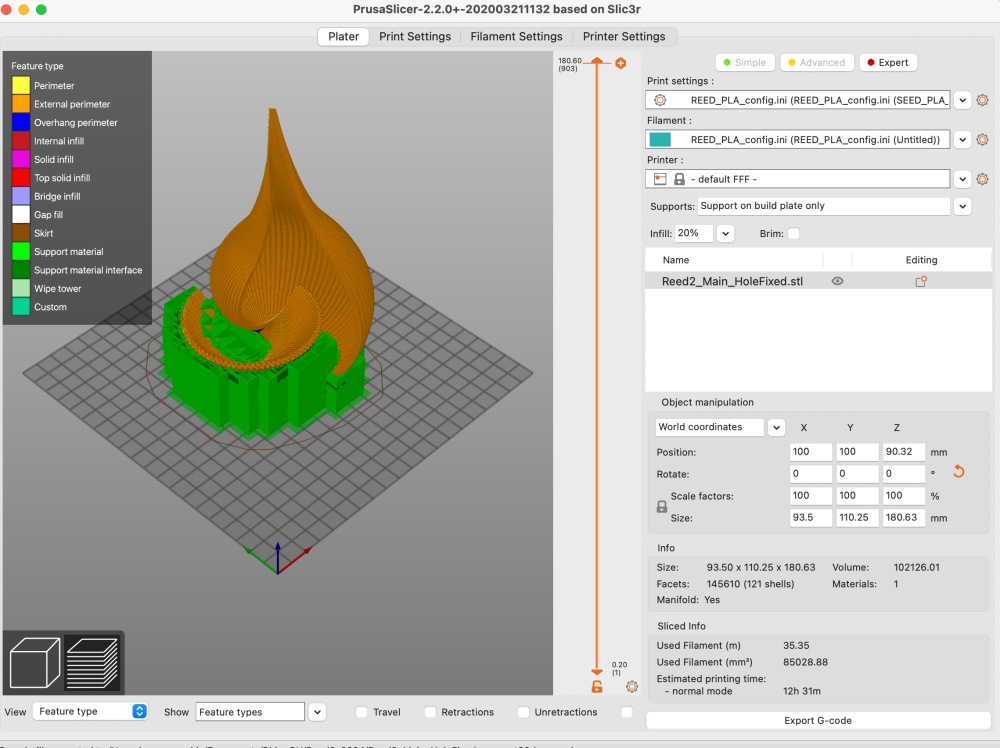
The fixed model was sliced by PrusaSlicer. The number of print layer was 5. Then printed with PLA.

BioFbricating
To increase the air resistance of the 3D printed Voronoi pattern Seed Wing, I decided to paint it with Bio Plastic. I made Agar liquid based on the recipe I did at week6 class, and applied it over the Voronoi.
2Recipe for Seed Wing
* Agar 5g   (Kanten)
* Glycerine 15g
* 250ml water
* cup
* scale
* spoon
* paintbrush
* Measure agar in the cup
* Pour water into the cup and stir it with a spoon.
* Boil for 2 minutes. I used the microwave. Stir occasionally. A large cup is better to avoid spills.
* Measure Glycerine, then pour into the agar liquid. Stir it.
* Paint it with paintbrush on the wing
* Leave it around one hour ( room temperature )
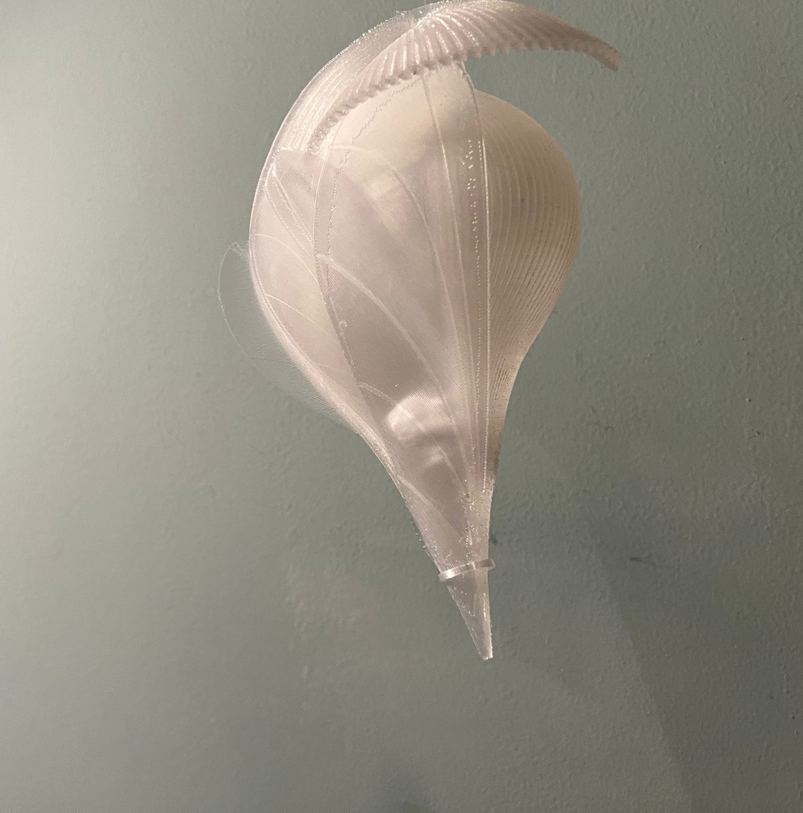
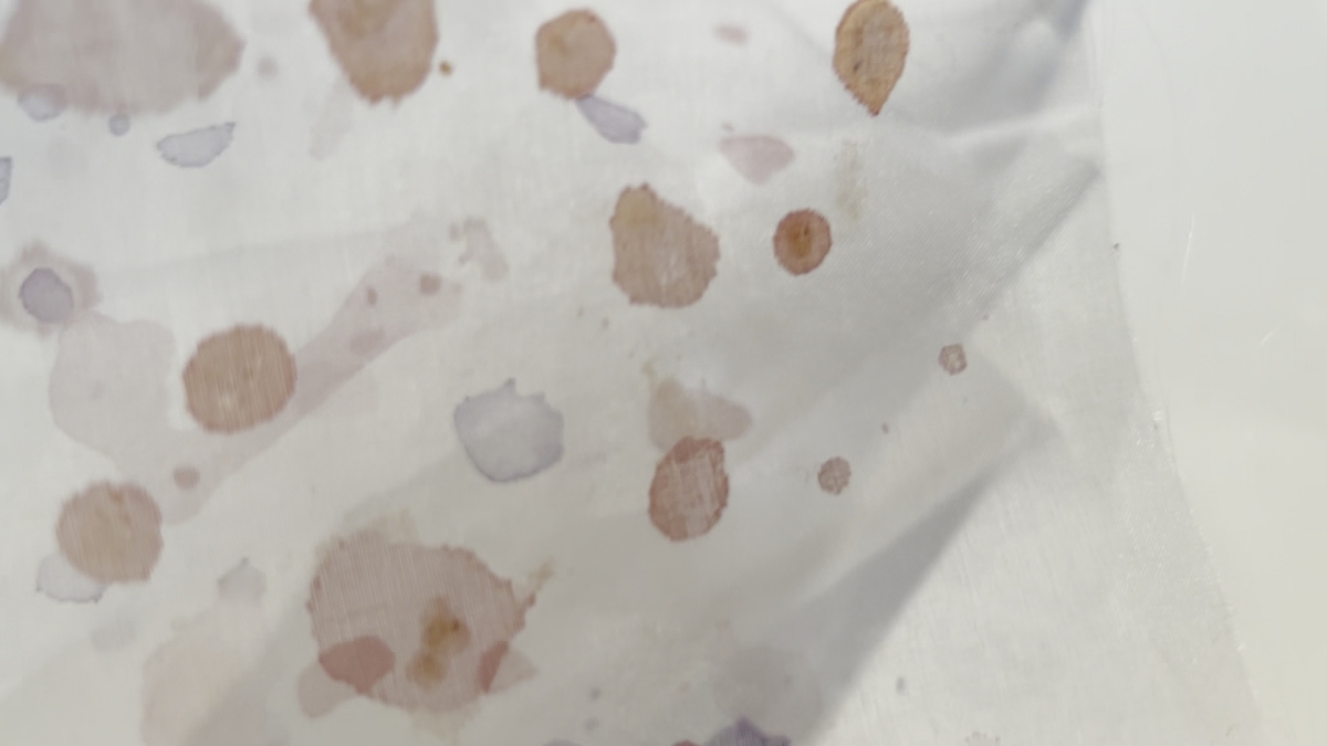
The one on the left is coated with BioPlastic, and the one on the right is uncoated. The painting on the left leaves holes. I thought about adjusting the size of Voronoi to make it easier to spread the membrane. but the wings of the species are actually porous. However, the research have shown that maple seed wings are actually porous, similar to dandelion wings, and that this helps stabilize flight. Therefore, I decided to leave the hole in the Seed Wing that I created as is. In the next step, I would like to try optimizing the porosity using Grasshopper's Kangaroo, etc.
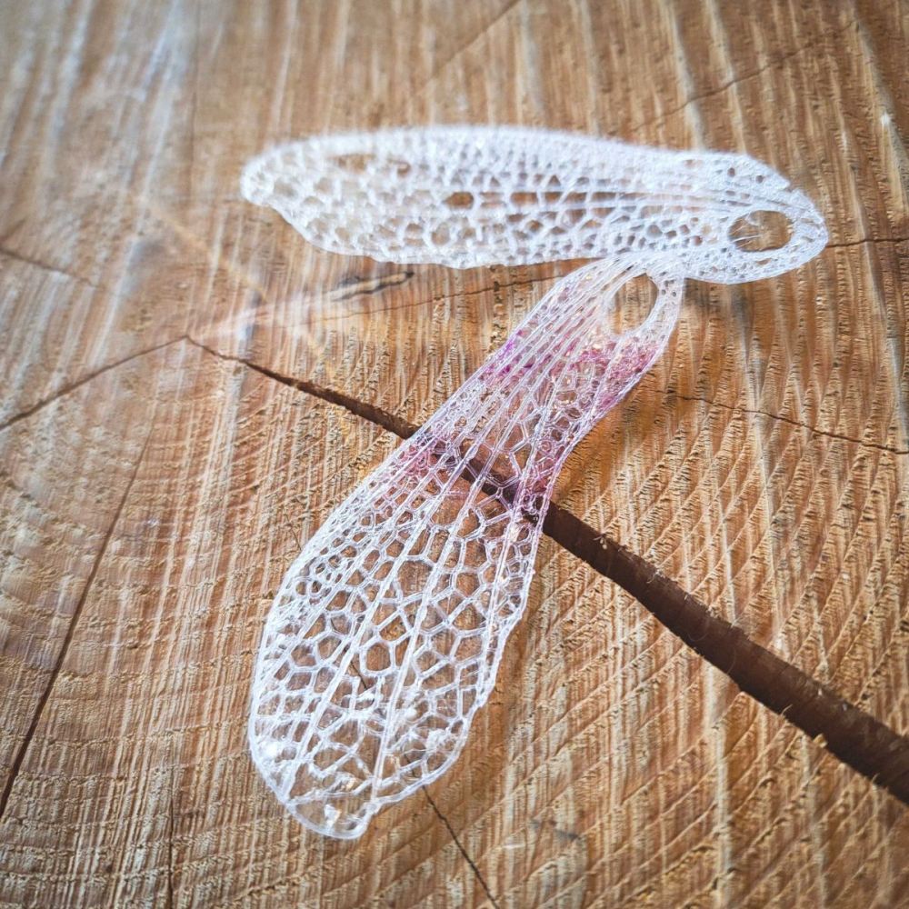
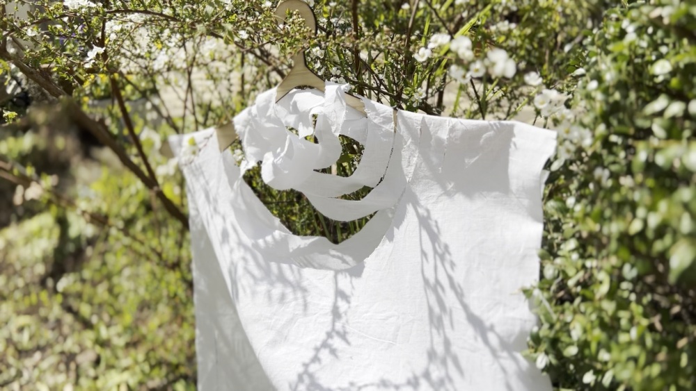
The pink seed wing below was not coated with colored bio plastic. When I immersed the tip of the seed wing in the purple cabbage dye solution and left it for a while, the dye solution rose up like capillary action and colored it.
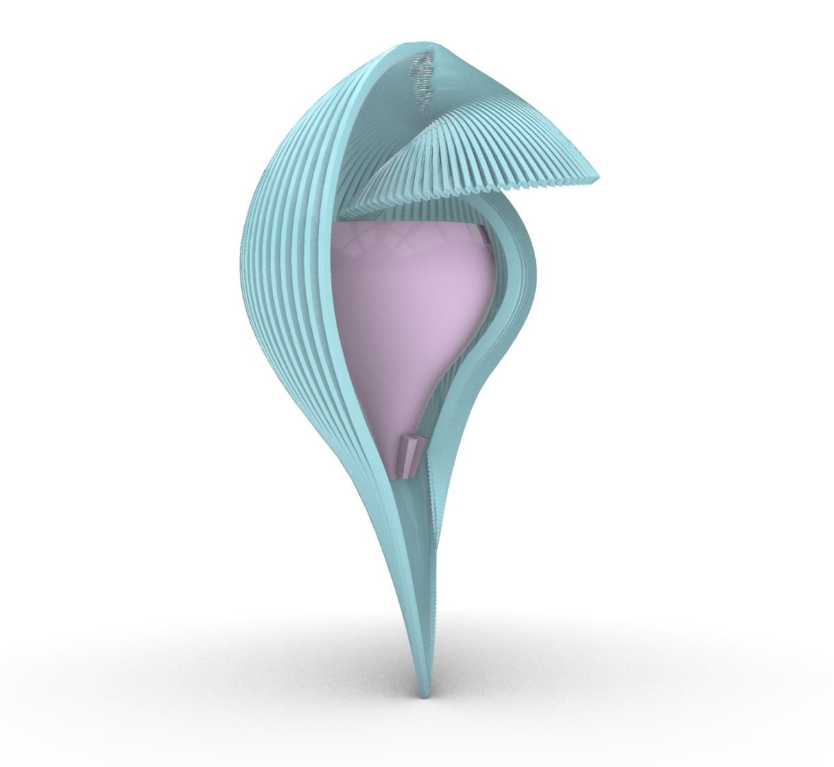
Main unit
The design of the main unit is basically the same as Process1. Small pillars were added to the bottom area of the Dye Unit to stabilize the artificial muscle mechanism.
Tune the size
It took a long time to be able to print the final size of the body, which is 18cm in height. I was using a 3D printer at home, but encountered various issues such as filament jams, loose belts causing layer shifts, and temperature abnormalities. Each time, I struggled to identify the cause and had to readjust the printer parameters multiple times to start over.
In the Prusa Slicer settings, one thing I paid attention to was minimizing the use of supports to make it easier to remove themfrom the unit. Moreover, since the print tended to detach easily from the heat bed, I initially printed at a very slow speed (around 30%) and gradually increased the speed once stability was achieved. I have also included my Prusa Config Data for my environment in the Fabrication Files.
Fabricate organic and functional
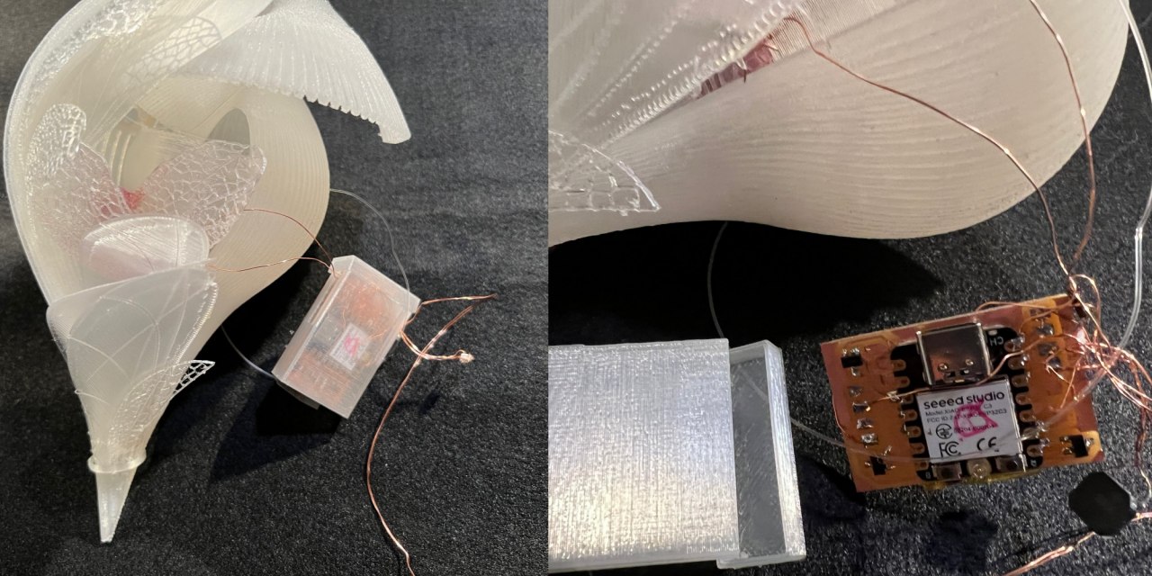
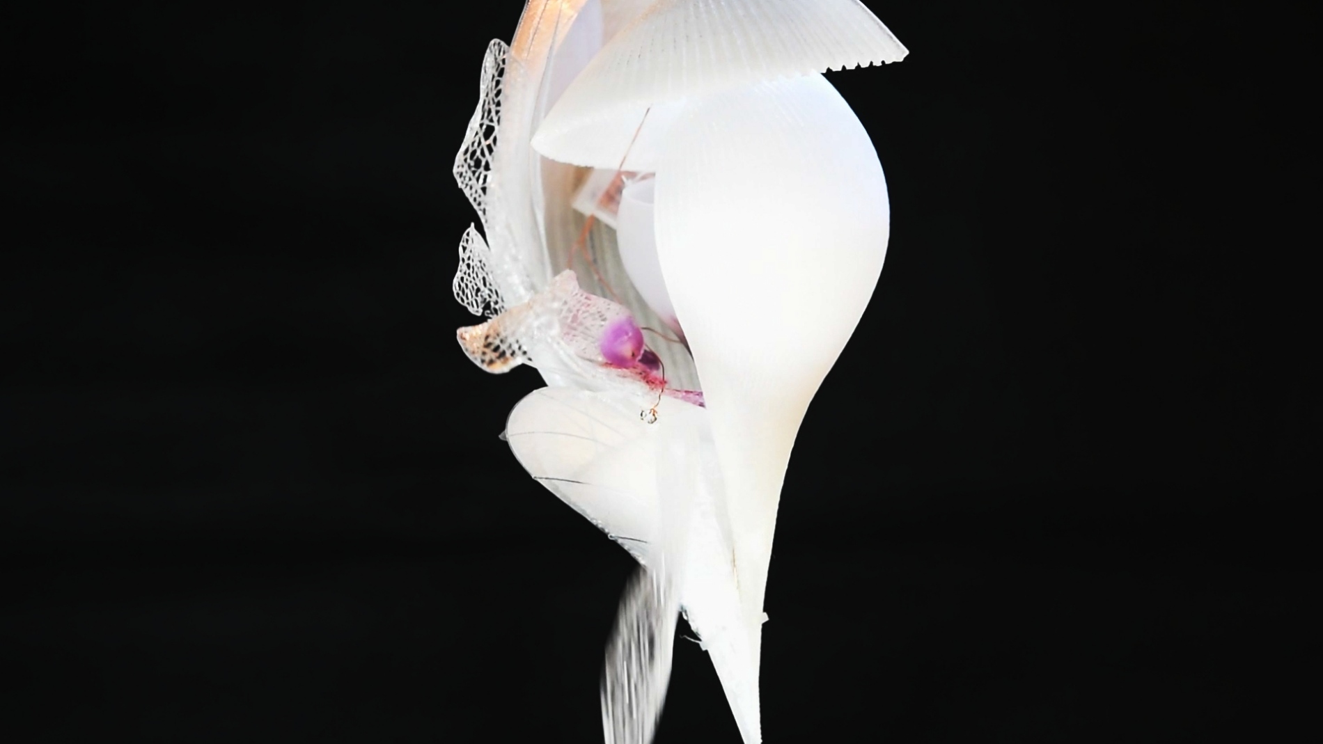
The 3D printed body was designed with an organic and beautiful shape. But how do I assemble the electronics and SeedWing while preserving the design? So I tried to combine seed wings with the main unit.

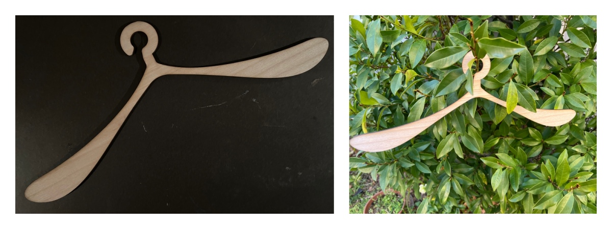
The 3D printed wings are flat. However, if you peel it off the 3D printer bed, roll it up in your hands to fit the shape of the main unit while it's still warm, and hold it until it cools down (about 1 minute), it will become a curved wing like the one below.
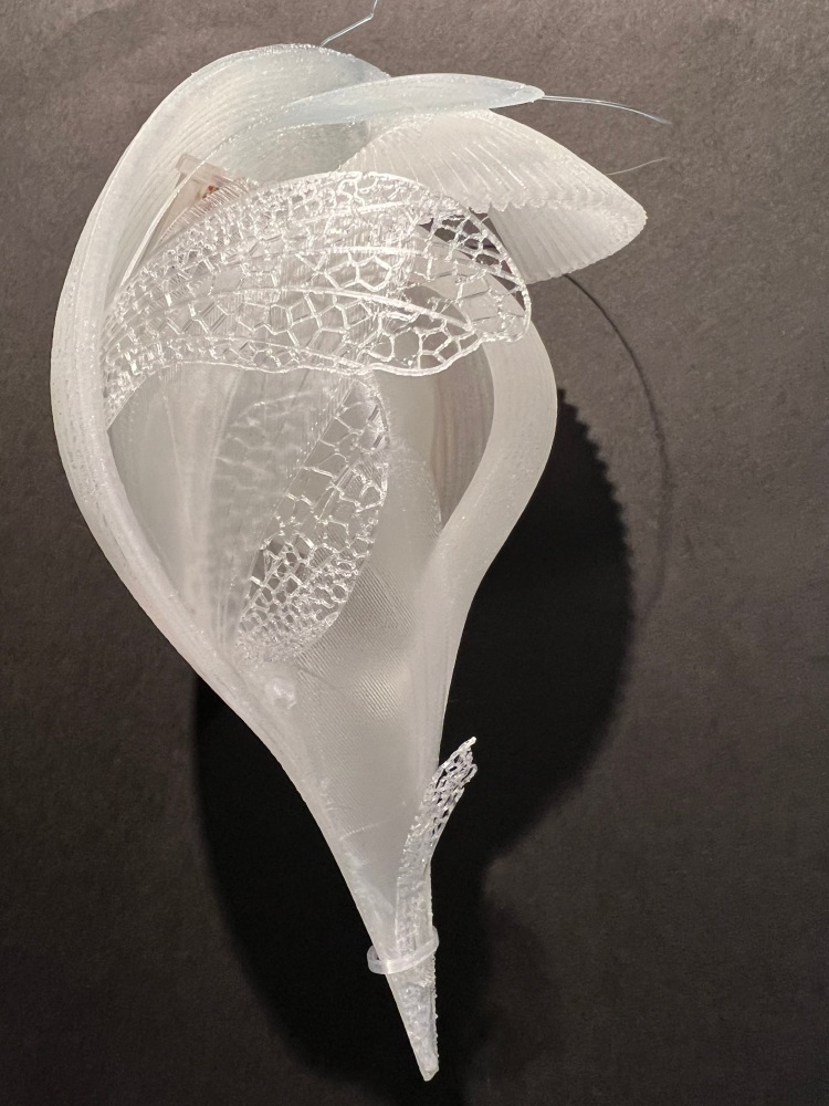

The base of the wings was glued to the Main Unit using the adhesive Acrisunday. Acrisunday is mainly used for adhering acrylic, but this time I used it for adhering PLA. The thin wings allow the top to be easily moved even when the bottom is glued to the main body, allowing you to move the dye unit, Seed Wing, and electronics in and out of the interior. When producing a shape like this by integrating it with an FDM printer, the influence of the support material becomes an issue. I think it was a good idea to print the hard unit and soft wings separately and combine them.

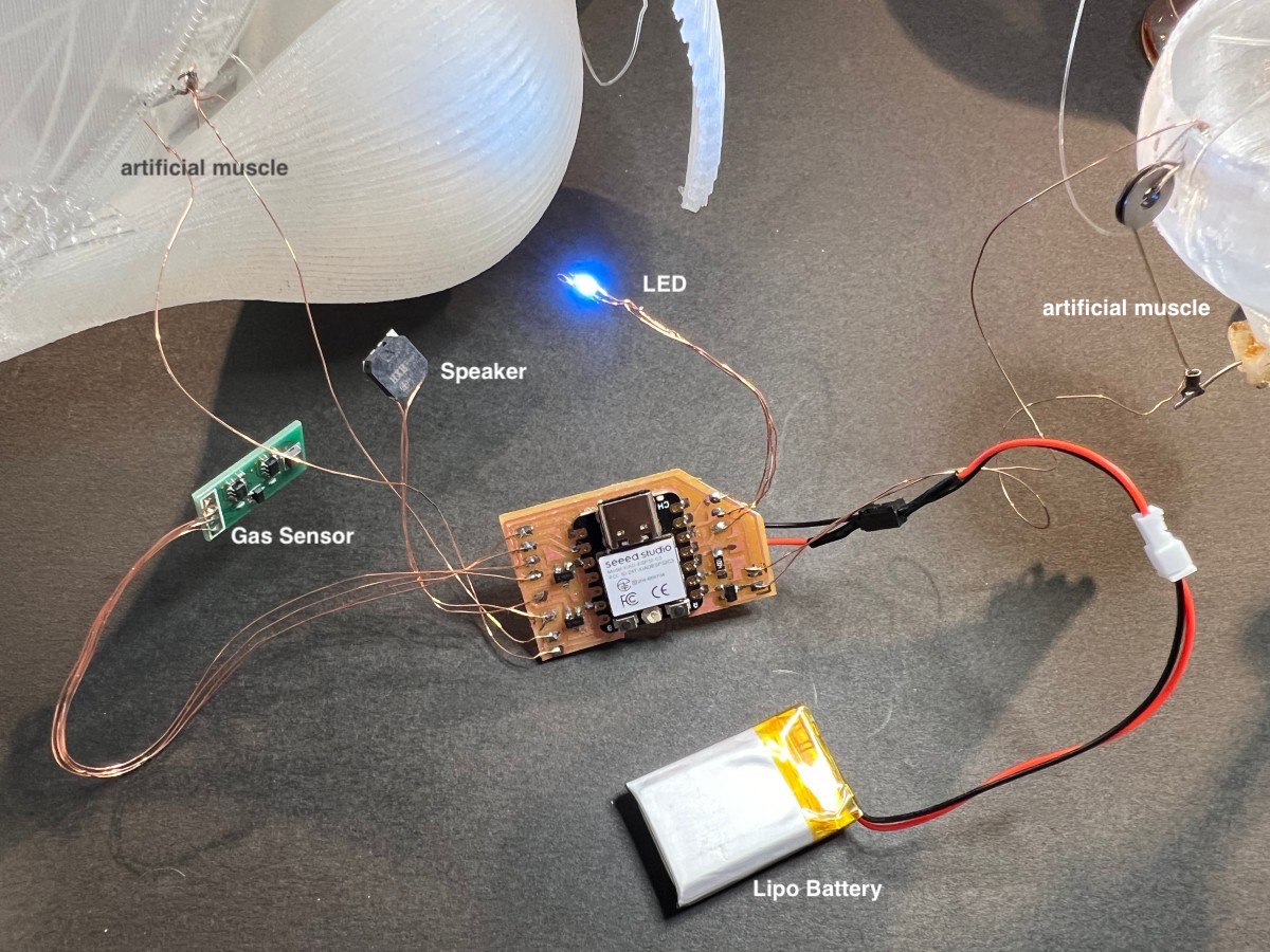
Electronics
This is a simple block diagram. Contains controls for speakers, LEDs, artificial muscles, and sensor units. This time, I added a touch sensor circuit using the remaining terminals. For example, when the user touches the MAin Unit, the sound or light can change.

Parts :
-
Micro controller board
- Small, low power consumption
- XIAO ESP32C3
-
LED
- NeoPixel : I used at E-textile week & Skin electronics week
-
Speaker
- Speaker: I used at Skin electronics week
-
Artificial muscle
- BioMetal: I used at Soft robotics week
-
Fermentation sensing
Bread board
Operation was confirmed on the Bread Board.

This is the change in sensor value when the gas sensor is placed in the Dye Unit.

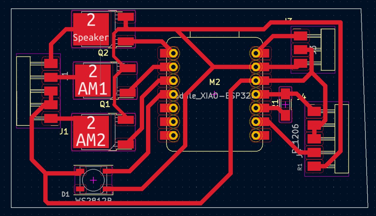
Circuit Board
Flexible circuit board
It seems difficult to install electronics inside while maintaining Reed's natural design. I didn't want to use a breadboard for the final project, so I challenged to make a flexible circuit board to fit the organic shape.
-
flexible PCB reference
-
Tool:
- KiCad
- Brother ScanNCut CM650W
- Copper foil tape
- Kapton Tape
- Clear file
- Polyurethane copper wire 0.16mm
I designed a circuit board using the Kicad 6 Tutorial as a reference.
Circuit diagram

Board design
Step:
-
Cut the clear file to the size of the board. Put Kapton tape on top and put copper sticker on top
-
Export the board data in SVG from KiCad, then changed the format to Jpeg by CorelDRAW.
-
The users manual of the ScanNCut is here. Import the Jpeg data into the ScanNCut. if the image settings are set to no lines and fill, change them to have lines and no fill.
-
Take path of the image using the scanNCut application.
-
Put the #1 material on the adhesive sheet. Cut with the parameter below.
- standard cut blade, blade scale setting = 6
- cutting speed = 1
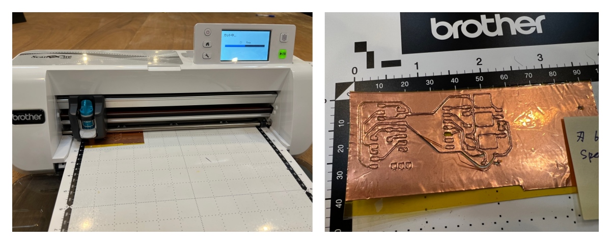
The cuts were crooked, curled up, and didn't always cut cleanly. Also, when removing unnecessary parts, necessary circuits are also cut off.

I didn't have time to cut it again, so I repaired it manually and soldered the parts.
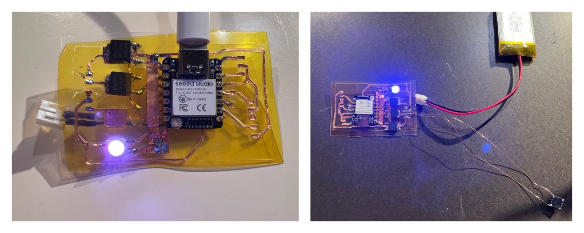
The circuit worked. However, there was a problem that the contact was poor and the LED would not turn on immediately. Re-soldering it would bring it back to life, but after doing this a few times, the operation became unstable. Flexible circuit boards turned out to be more difficult than I had imagined.
Hard (normal) circuit board 1
The flexible board was fragile, so I decided to try a regular hard board. I learned how to use the SRM-20 at FabAcademy.
-
Tool:
-
Reference
There were some mistakes in the circuit, so I corrected them manually. As a result, it worked as follows. The biggest problem was that I hadn't thought about connecting the Lipo Battery to the back. In other words, I soldered the parts without making a hole for the battery. So I connected dry batteries (1.5V*4) to 5V pin of the XIAO. When USB is connected, 5V pin is 5v out from the USB port. But if not connected, you can also use this as a voltage input. Please note that if you connect an external battery to the 5V pin and update the code via USB, you will need to connect a diode. anode to battery, cathode to 5V pin.

Hard circuit board 2
I had some regrets about the circuit and the Lipo Battery, so I made the board again.
Kicad6 Circuit design

Kicad6 Board design

I created a path for cutting the circuit with SRM20 using Mods. 1/64mm bit was used. See the Mods screen for detailed settings.
Cutting path
Next, created a path for board outline. 1/32mm bit was used.


First, connect the USB and check if it works. I can check the sensor values and program mode using the Arduino IDE's serial monitor.
Next, connect the 3.3V Lipo Battery, and confirmed the operation.

SoftRobotics
The operation of opening the silicone stopper was unstable, so improvements are being made.
- 1st version
Pull the stopper straight down.
- 2nd version
Use leverage to move.
- 3rd version
Added a wall to the Dye Unit to guard the lever, making it work better.
The image below shows Seed Wing falling from the Main Unit. A thin wing is attached to the Main Unit to prevent the Seed from falling. When the time comes for flight, a microcontroller controls artificial muscles to open the thin wings outward, making it easier for the seed to fall.
Programming
Gas Sensing using interrupt
I have already confirmed that the sensor can be read by itself. However, modifications are required to incorporate it into the overall program. Because the gas sensor value requires inputting pulses at a 1ms cycle as shown below. In the entire program, other processing will also take time, so it will be necessary to use such as timer interrupts to control this sensor.

So I tried the Ticker Library.
First, I changed the single program that reads sensor values as follows, and confirmed that the values were read every second properly.
int adval = 0; //
float sensor_r;

Ticker timer;

void readADC() {
  digitalWrite(D0, HIGH);
  delayMicroseconds(1);
  adval = analogRead(A1); //
  delayMicroseconds(1);
  digitalWrite(D0, LOW);

  if (adval != 0) {
    // ((3.0 / (adval * 5.0 / 4096.0)) - 1) * 10k
    sensor_r = 6144.0 / adval - 10;
    Serial.println(sensor_r, 1);
  } else {
    Serial.println("div 0 ");
  }
}

void setup() {
  Serial.begin(115200);
  pinMode(D0, OUTPUT);
  timer.attach(1.0, readADC); // Interupt every 1sec
}

void loop() {

}
Total Code
The program performs the mode transitions shown below. All program processing runs on the ticker's 998msec timer. The only thing that requires a 1-second interval is gas sensor acquisition, but this time I decided that there would be no problem in running other processes within the 1-second interrupt, so I created the simple structure.
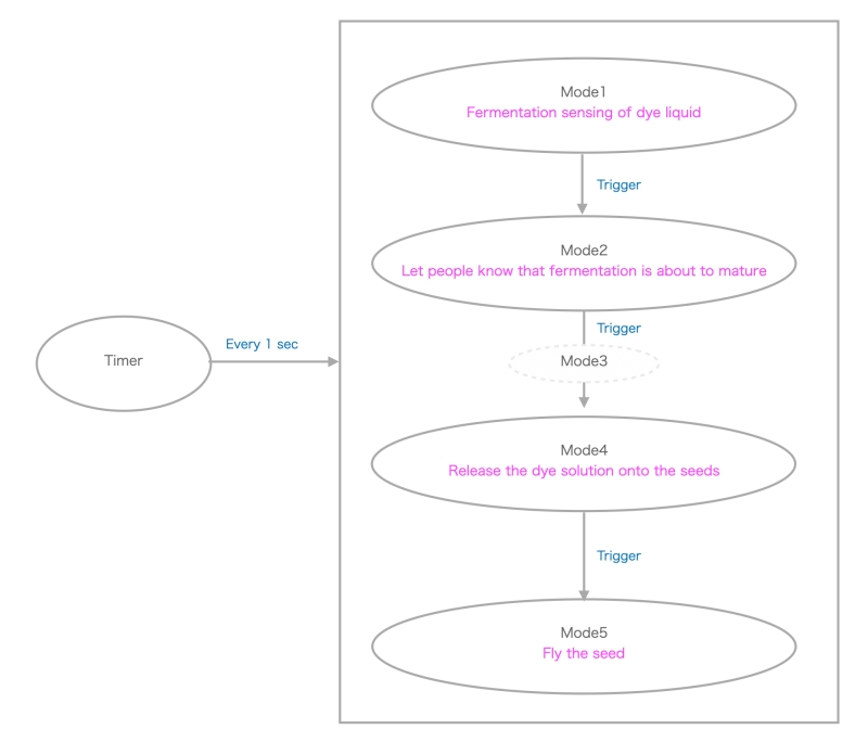
When the program starts, it first enters Mode 1. A gas sensor measures the degree of fermentation of the dye solution, and when it is sufficient, it switches to Mode 2.
This research confirmed that fermentation could be sensed with the sensor. But I didn't have time to find the optimal fermentation completion value for each ingredient.
Therefore, this program uses the elapsed time to trigger Mode2.
Mode 2 tells people that fermentation has progressed. In the program, the way it lights up (LED color) changes and plays a tone. This time, rather than a song, the format is a random pentatonic sound. Although the system will be larger, I can also use the unit used in the Open Source HW Class that can play MP3. People feel the four seasons through tones and colors. Those who wish to dye their fabric should make preparations such as setting it around the Reed.
Mode 3 is a buffer mode. I had a problem where even if I stopped the tone, it wouldn't stop ringing if there was data in the buffer, so I added a buffer-like mode. There may be other solutions.
Transitions from Mode2 to Mode3, Mode4, and Mode5 are performed based on elapsed time. In Mode 4, uncork the Dye Unit, and in Mode 5, open the wings covering the Main Unit to make it easier for the seeds to fall out.
This program uses three MOSFETs to control the speaker, artificial muscle 1, and artificial muscle 2. When two or more MOSFETs were used at the same time, the microcontroller's operation became unstable, causing frequent resets. To solve this problem, this program limits the number of MOSFETs to one in each mode. Another solution could be time-shift the multiple MOSFET operations.
/************************************************************
 *   Fabricademy FP
 *
 ************************************************************/
#include <Arduino.h>
#include <Ticker.h>

Ticker timer;

// NeoPixel
#include <Adafruit_NeoPixel.h>
#define PIN  D10// Neopixel pin
//#define PIN  D8// Neopixel pin
#define NUMPIXELS 1 // Number of NeoPixels
Adafruit_NeoPixel pixels(NUMPIXELS, PIN, NEO_GRB + NEO_KHZ800);

//Speaker
#define spPin D2//

//int mScale[]={131,165,196,262,330,392,523,659,784,1047}; //C#3, E#3, G#3,  ---
//int mScale[]={277,311,329,391,440}; //C#4, D#4, E#4, G#4, A#4)
int mScale[]={880,1046,1174,1318,1567,1760}; //A#4,C#5, D#5, E#5, G#5, A#5)
int mScale2[]={2093,2349,2637,3135,3520}; //C#6, D#6, E#6, G#6, A#6)

//BioMetal
#define amPin1 D7//
#define amPin2 D5//
//#define amPin2 D4//

//Touch
//int f=0;//フィルタ用変数
//const int touchOutPin = D8;   //
//const int touchInPin = D9;  //


//Gas Sensor
const int gasOutPin = D0;   //
const int gasInPin = A1;
int gasVal = 0; //ADC data
float sensor_r;

//Mode
int appMode=0;
//unsigned long timCnt; //mills
unsigned long lpCnt=0;; //

int time1 = 90;
int time2 = time1+30;
int time3 = time2+10; //buffer
int time4 = time3+10;
int time5 = time4+1;

bool  isLED = true;
int ledBr = 100;
int br=4;
//int counter=2000;


void setup() {
  //NeoPixel setup
  pixels.begin(); // INITIALIZE NeoPixel strip object (REQUIRED)
  pixels.clear(); // Set all pixel colors to 'off'


  //Touch setup
//  pinMode(touchOutPin,OUTPUT);  // send pin
//  pinMode(touchInPin,INPUT);  //receive pin


  pinMode(amPin1,OUTPUT);  //
  pinMode(amPin2,OUTPUT);  //

  //Gas sensor setup
  pinMode(gasOutPin, OUTPUT);
  pinMode(gasInPin, INPUT);

//  Serial.begin(115200);
  Serial.begin(9600);
  timer.attach(1.0, intMain); // Interrupt every 1sec

}


void loop() {
 // Serial.println("==== loopTest ====");  //----temp
}

void intMain(){

  chkMode();

  switch(appMode){
    case 0:
      mode0();
      break;
    case 1:
      mode1();
      break;
    case 2:
      mode2();
      break;
    case 3:
      mode3();
      break;
    case 4:
      mode4();
      break;
  }

}

void mode0(){
  act1off();
  act2off();
 isLED = true;

  dspLed(0);

   //noTone(spPin);
  chkFerment();
  //chkTouch();
}

void mode1(){
  dspLed(1);
  randomTone();
  //chkTouch();

}

void mode2(){   // buffer to stop tone
  noTone(spPin);
  dspLed(2);
}

void mode3(){
  noTone(spPin);
  dspLed(2);
  chkAct1();

}

void mode4(){
  noTone(spPin);
  dspLed(3);
  chkAct2();

}

void chkMode(){
  if( lpCnt< time1){
      appMode=0;
    }else if(lpCnt < time2){
      appMode=1;
    }else if(lpCnt < time3){
      appMode=2;
    }else if(lpCnt < time4){
      appMode=3;
    }else if(lpCnt < time5){
      appMode=4;

    }else{
      appMode=0;
      act2off();
      lpCnt=0;
    }
    lpCnt++;

    if( appMode !=0){
        Serial.print(" lpCnt = ");
        Serial.println(lpCnt);
    }

}

void chkFerment(){
  chkGas();
}

void chkAct1(){
  act2off();
  analogWrite(amPin1, 200);
  Serial.println(" ******AM 1 ON");
}

void act1off(){
     analogWrite(amPin1, 0);
}

void act2off(){
     analogWrite(amPin2, 0);
}

void chkAct2(){

 act1off();
 //isLED = false;
 analogWrite(amPin2, 180);
 Serial.println(" ******AM 2 ON");
}

void dspLed(int ledMode){

  if(isLED){

    for (int i = 0; i < NUMPIXELS; i++) { // For each pixel...
      // pixels.Color() takes RGB values, from 0,0,0 up to 255,255,255
      switch(ledMode){
        case 0:
            pixels.setPixelColor(i, pixels.Color(105, ledBr, 255));
            break;
        case 1:
            pixels.setPixelColor(i, pixels.Color(255, 105, ledBr));
            break;
        case 2:
            pixels.setPixelColor(i, pixels.Color(ledBr, 255, 255));
            break;
        case 3:
            pixels.setPixelColor(i, pixels.Color(ledBr, 255, 255));
            break;

      }
      pixels.setBrightness(ledBr);
      pixels.show();   // Send the updated pixel colors to the hardware.
    }
    ledBr += br;

    if(ledBr<5){ br=4;}
    else if(ledBr >250){ br=-4;}
    //Serial.print("ledBr=");

  }else{
    pixels.clear(); // Set all pixel colors to 'off'
    pixels.show();
  }
}


void randomTone(){
//  tone(spPin, mScale[random(sizeof(mScale)-1)], random(10,150));  //

 // if(!touchOn){
    tone(spPin, mScale[random(sizeof(mScale)-1)], random(100,180));  //
 // }else{
 //   tone(spPin, mScale2[random(sizeof(mScale)-1)], random(30,60));  //
 // }
}


void chkGas(){

   digitalWrite(gasOutPin, HIGH); //PULSE pin HIGH
   delay(1); //Wait until OUT stabilizes
   gasVal = analogRead(gasInPin); //ADC
    //  Serial.println(gasVal);
   delay(1); //
   digitalWrite(gasOutPin, LOW); //PULSE pin HIGH
   if (gasVal != 0) {
      //((3.0 / (adval * 5.0 / 1024.0)) - 1)*10k ohm
      //sensor_r = 6144.0 / gasVal - 10;   // for 5V
      sensor_r = ((3*1024/gasVal*3.3) -1) *10;   // for 3.3V

      Serial.println(sensor_r, 1);

    }
    timer.attach(0.998, intMain); // Interupt every 998msec
}
XIAO trouble shooting memo
When using XIAO, I repeatedly encountered problems such as not being able to upload code or not being able to recognize devices. If you search on the internet, you will find that many people are having the same problem.
According to the XIAO ESP32C3 Wiki:
Q1: My Arduino IDE is stuck when uploading code to the board
  You can first try to reset the board by clicking the RESET BUTTON once
  while the board is connected to your PC. If that does not work, hold
  the BOOT BUTTON, connect the board to your PC while holding the BOOT
  button, and then release it to enter bootloader mode.

Q2: My board is not showing up as a serial device on Arduino IDE
  Follow the same answer as for Q1 above.

Q3: I want to reflash the bootloader with factory firmware
  How to write Factory Firmware to Flash using ESP RF Test Tool is explained
  in the wiki.
I tried Q1 but it didn't solve it. Next, I tried the Q3 Tool. I couldn't run the downloaded tool in my Mac environment, so I tried to rewrite the firmware on my Windows PC, but a connection error occurred.
There was a note about I/O allocation on the Seeed engineer's blog. Among them, the problem with my circuit was the D8 port. Seeed Studio XIAO ESP32C3's D8 is connected to ESP32-C3's GPIO8 (14). GPIO8 is referenced when you start up while holding down the BOOT button and set the boot mode to download boot, and it seems that it must be HIGH at that time. In other words,
- when using download boot, you need to add a pull-up resistor at D8 to make GPIO8 go HIGH at boot time.
Why isn't this important thing written on the Wiki? This port was used for touch detection for future use. I removed the soldered resistor and pulled it up with a 10KΩ resistor. When I rewrote the firmware using the ESP RF Test tool again, it worked fine. Though I had to push Boot button (usually not necessary) when I uploaded a new code at Arduino IDE, I could upload it successfully after the LONG winding road!
Variation

During the mid-term review, there were some questions about whether the units would be recycled. The current unit is made with the assumption that it will be recycled. I want to be able to check the location using the app. On the other hand, some units may be returned to nature without being recycled. This time, I tried creating a unit using instructor Rico's clay printer.
Clay unit
As a natural material, I tried the Clay Printer for the first time at instructor Rico-san's Lab. Not only is the material itself environmentally friendly, but the material is also easily recyclable.
Tool:
- Clay Printer Delta WASP 2040
- Air Compressor
- Fusion360: Mesh repair
- PrusaSlicer: Slicer
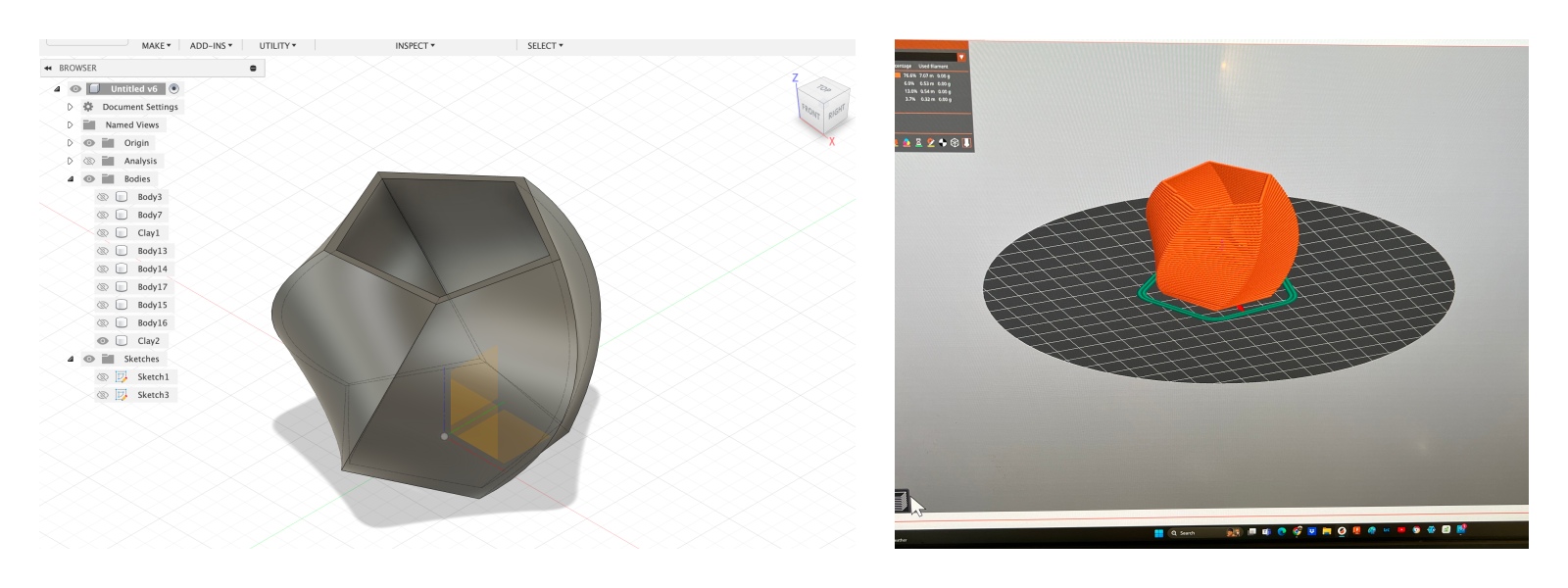
Design
The model was designed using Fusion360. Very simple small one for the 1st trial. For Slider, I used Prusa Slicer. There are no different steps compared to regular 3D printers, but the data is created by importing the configuration adjusted by the manufacturer.
Clay preparation
I used this video as a reference for how to use the Clay Printer.
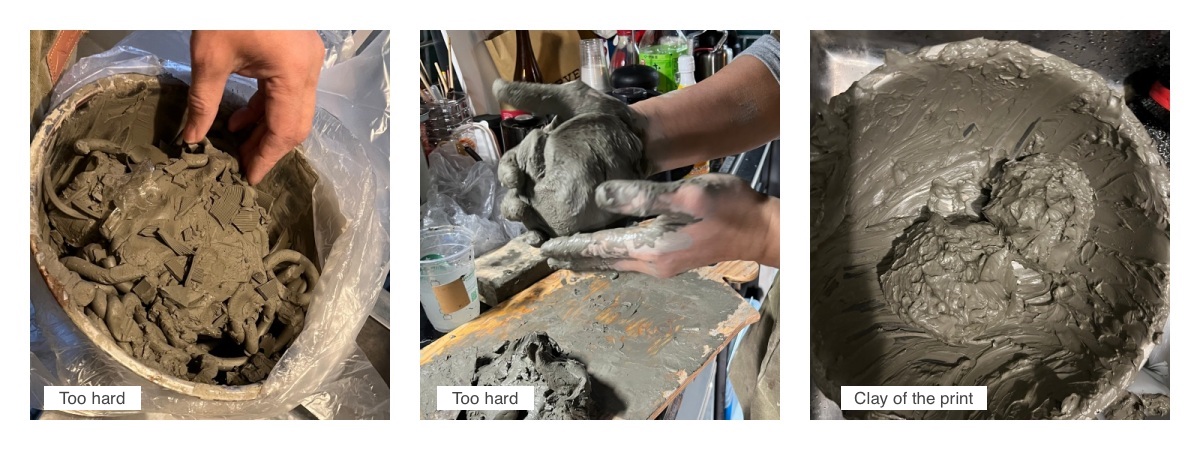
Many failures!
 Important 1st layer

Result:

Dry process:

Water proof:
I tried to make it waterproof by applying a varnish that is used for paper clay.

This unit appears as a "new species of REED" in the World News video of the final presentation.
Final video props
In between main unit trials, I created props to use in the final video scene.

I plan to use the cloth dyed with Reed to make a Zero Waste Garment like below I designed in the week3 class.
Final Video
Script 1st draft
SCENE1 - Title
    - Main Title: Reed
    - Sub Title: Breath of Days
    - Fabricademy 2023/2024
    - Fablab Kamakura

SCENE2 - TV news
    - News on cherry blossom flowering prediction in Japan
        - Sublime Japanese scenery
        - The beauty of falling petals
    - News on Reed’s fermentation (glow) prediction news for this year ( in Japan).
        - Video: Reed under cherry blossom tree. (If weather and timing are good )

SCENE3 - User’s Kitchen
    - Show everyday life. Reed’s news on TV screen (chumby)
    - User’s issue: How can I integrate sustainability seamlessly in my daily life ?
    - Time laps video
        - Put leftovers and water in the Reed unit
        - Assemble the Reed ( Dye unit, seed wing ... )
        - Pause occasionally and use arrows to explain Reed’s technical characteristics

SCENE4 - Park
    - Hang Reed on a tree
    - Show the process of fermentation
        - Show color changes by dropping liquid, etc.
        - Sensor graph movement
    - Music
        - Show progress with music that includes clock sounds SCENE5 - Reed unit, Park
    - The time has come
        - Glowing. Overlapping tones from multiple units. ○ Close-up of movement
    - People notice Reed
        - Stop to hear the Reed sound.
        - A child approaching
    - Person who brings fabrics

SCENE6 - Flying Seed
    - flying seeds slow motion
    - ink spreading on fabric / zero waste garment
    - Process some invisible patterns on the fabric so that ink spreads beautifully?

SCENE6 - Community
    - Meet with Fablab Kamakura members
    - Workshop with children
    - Fun photo/videos
    - design variations (sketch?)

SCENE7 - TV news on Reed
    - Popular all over the world. (world map)
    - New species discovered in the forest!

SCENE 8 - End credit
Script 2nd version
Final Video
Exploring Future Endeavors
The first prototype has been completed. Next, I aim to tackle new challenges in pursuit of further evolution
-
Power supply
Explore sustainable options such as solar power for energy provision. -
Biodegratable
Investigate alternative materials to PLA for the Main Unit and Seed Wing.
Research biodegradable options for electronics. -
LED, Sound
Enhance lighting and sound effects to correspond with fermentation progress. -
Waterproof
Implement measures to protect electronics from rain damage. -
Mechanism
Enhance the durability and reliability of fragile components. -
Open source
Consider open-source solutions for broader accessibility and collaboration. -
Variation
- Electronics-Free: Experiment with designs that do not rely on electronic components.
- Remote Control: Explore interactive features for remote control and user engagement.
- Interactions: Positive/Passive
Mentoring notes
Feb.28
- complex system and other needs to be finished before the deadline - priority
- what is the position of humans in this process? - you don't need a system we as humans can do it
- we as humans could listen to the sound, interaction with falling dye
- have you thought about the relationship between the dyes and the knowledge inside (recipe, source, application) to enjoy the experience beyond
- biomaterials instead of clay
- diverse textures and objects regarding the material and technique you are using for the object
fabrication files
-
Seed Wing Design Grasshopper
Seed Wing STL file @ Thingiverse: Link
Seed Wing 3D Print @ Prusa config data ↩ -
Seed Bio Plastic Recipe ↩
-
Main Unit Design Grasshopper
Main Unit 3D Print @ Prusa config data
Main Unit STL file @ Thingiverse: Link ↩ -
Circuit board Kicad Schematic,Kicad PCB, circuit svg, outline svg,SRM20 circuit rml,SRM20 outline rml ↩