12. Skin Electronics
Research
The body as a circuit ! Skin electronics is about bringing technology into contact with the most personal interface we have (our own body). making something that sits on or against the skin and responds to what the body is doing from the inside out.
The work of Stephane has inspired me here as a method of creating a design - Check here Also Haneen Jaafreh work inspired me to design storytelling and integrate it with 3d print.Check here which is something i already worked on with wearable
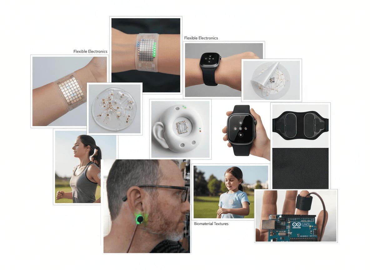
MoodBoard
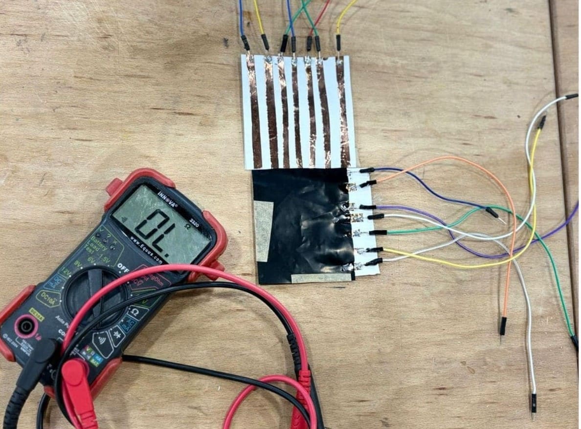
Experimentation - pressure sensor
Lab experimentation with making pressure sensor .A matrix touch sensor works as a grid made of rows and columns of conductive lines. Where these lines cross, each point can sense touch. A pressure-sensitive material like velostat is placed between the layers, and when you press on it, its electrical resistance changes. The system reads this change to figure out both where the touch happened and how strong it is. This kind of sensor setup is commonly used to map pressure across a surface, like in touchpads or interactive materials.
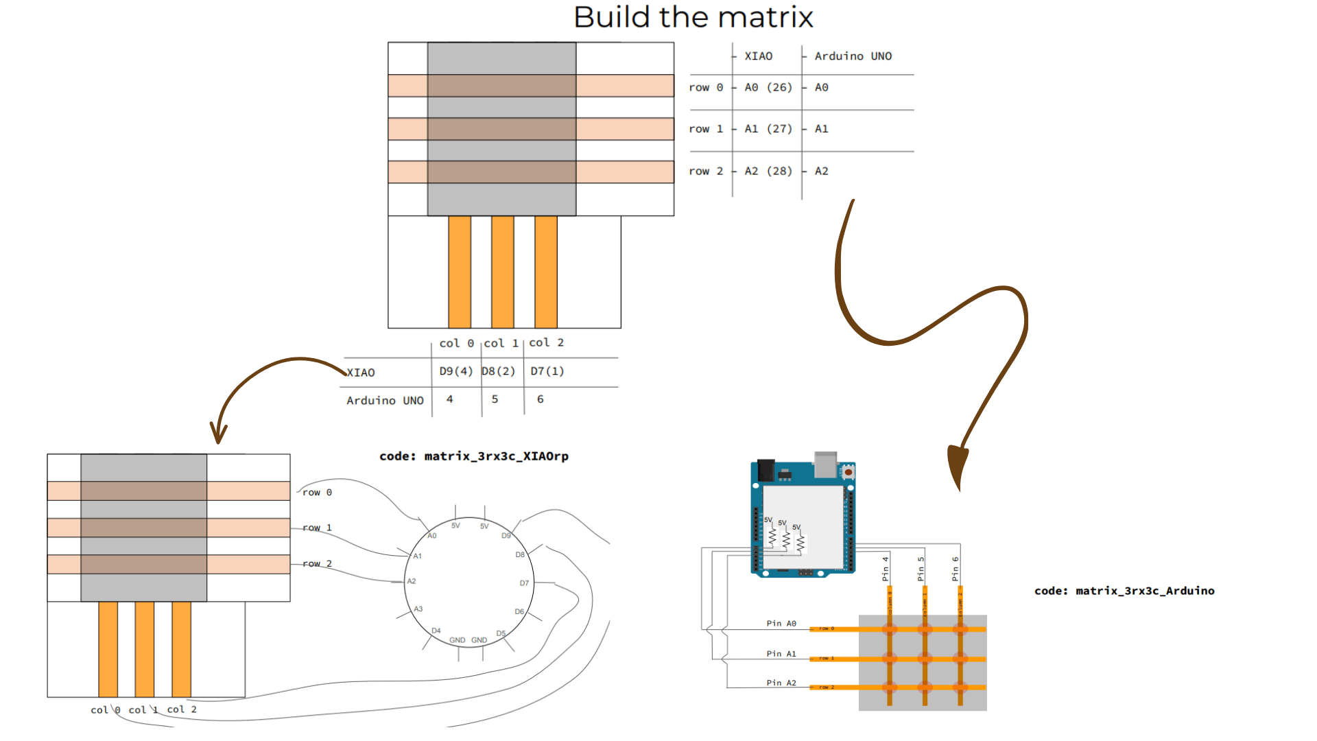
The way to connect
Tools
- Arduino IDE → to write and upload code
- Jumper wires → to connect components
- Microcontroller (like Arduino) → reads and processes the signal
- Pulse heart sensor
- LED
- Resistor
Process and workflow
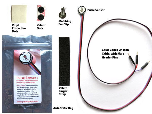
Pulse sensor toolkit
Concept
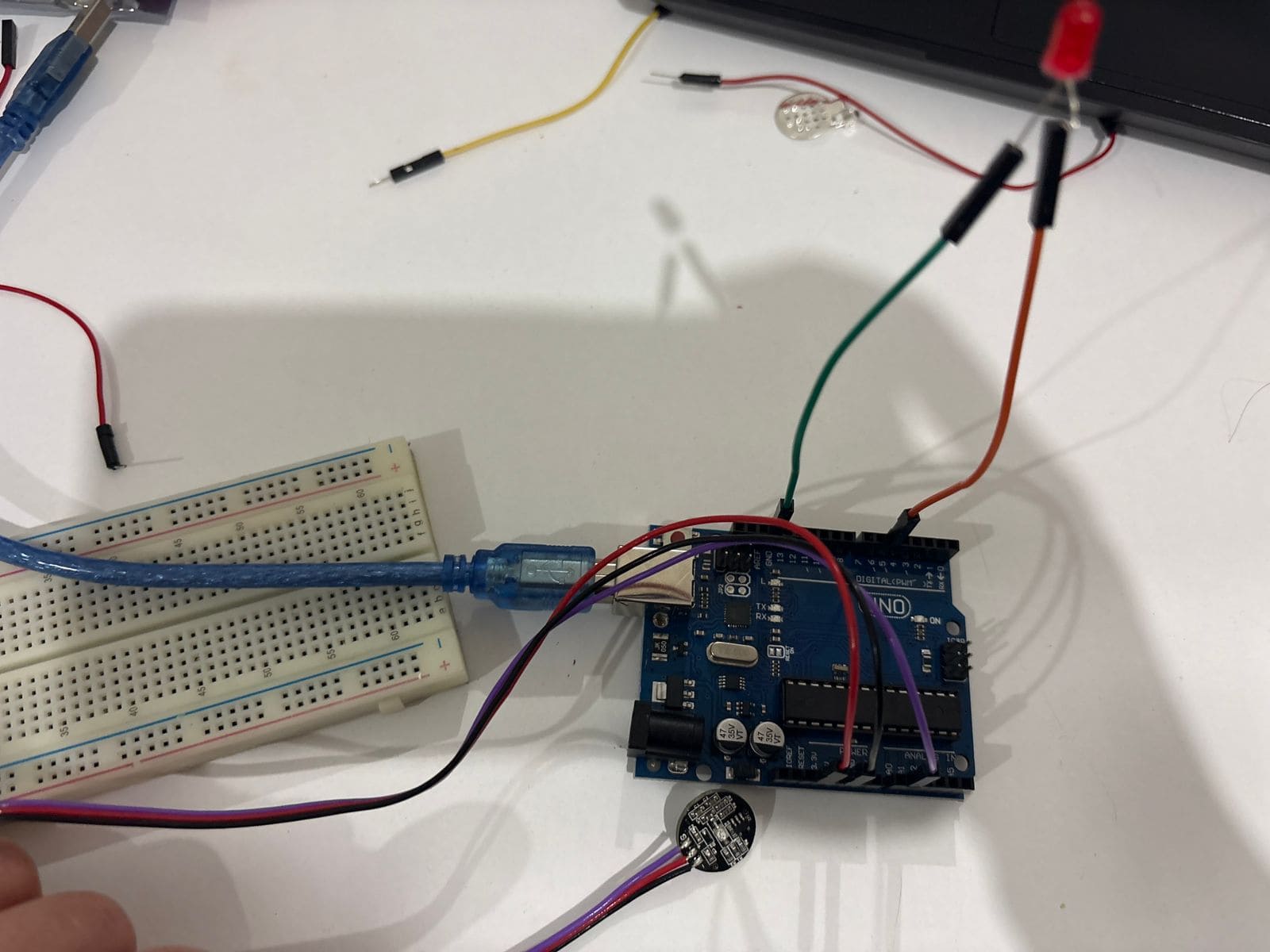
This week, I worked with a pulse sensor .a small circular board that you press against a fingertip and it reads your heartbeat. The output is a live analog signal that represents heart pulse waveform, and the goal was to make that signal visible: through numbers on a serial monitor, through a graph, and through a physical LED that blinks with each beat.
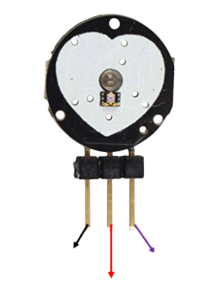 As you can see here the legs for sensor for GND(-),Analoge,voltage(+) and i will explain more about how to be connected , but please make sure to check them too as sometimes with a few models i noticed there might be minor diffrence in the sequence for example analoge and GND .
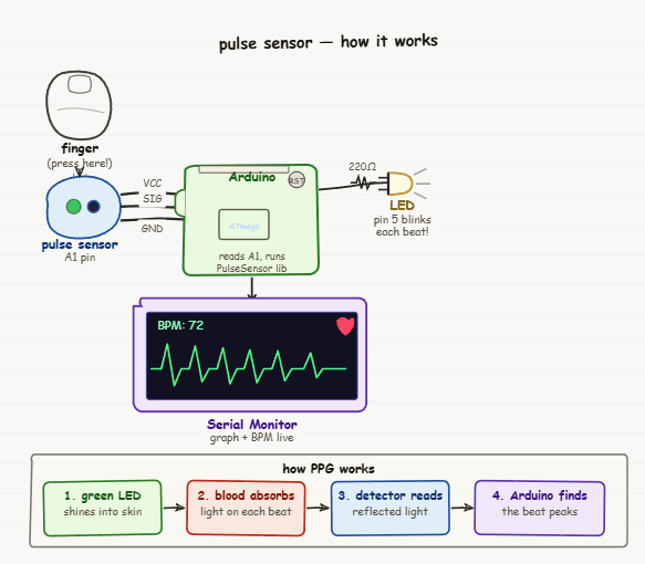
How the pulse sensor actually works
The pulse sensor works using a technique called photoplethysmography (PPG) but in simple terms, it’s just using light to “see” your heartbeat.
On the front of the sensor, there’s a small green LED that shines light into your fingertip. Right next to it, a tiny detector (photodiode) measures how much of that light comes back.
What’s interesting is that blood absorbs green light more than the surrounding skin. So every time your heart beats, more blood flows through your fingertip for a brief moment. During that instant, more light gets absorbed and less is reflected back.
This creates a small, repeating change in the signal — a rise and fall that follows your heartbeat. By tracking this pattern, the sensor can read your pulse in real time.
Understand the pulse circuit
Components and Connections
| Component | Connection | Notes |
|---|---|---|
| Pulse Sensor — purple wire | Arduino A1 | Analog signal output |
| Pulse Sensor — red wire | Arduino 5V | Power |
| Pulse Sensor — black wire | Arduino GND | Ground |
| LED long leg (+) | 220Ω resistor → Pin 5 | Always use resistor or LED burns out |
| LED short leg (−) | Arduino GND | Long leg = positive toward pin 5 |
White Board
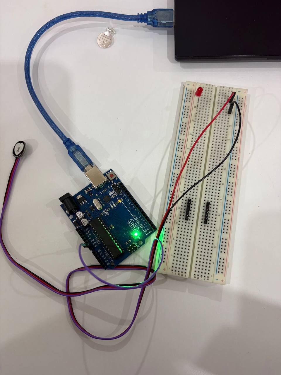
I started on the white board + Arduino uno microcontroller with LED and Puldse sensor , it could be good to start on as a sketch or have many LED .
Connect directly on arduino uno
As you can see i have one LED so i made the sketch test then connected directly on arduino uno microcontroller as you can see
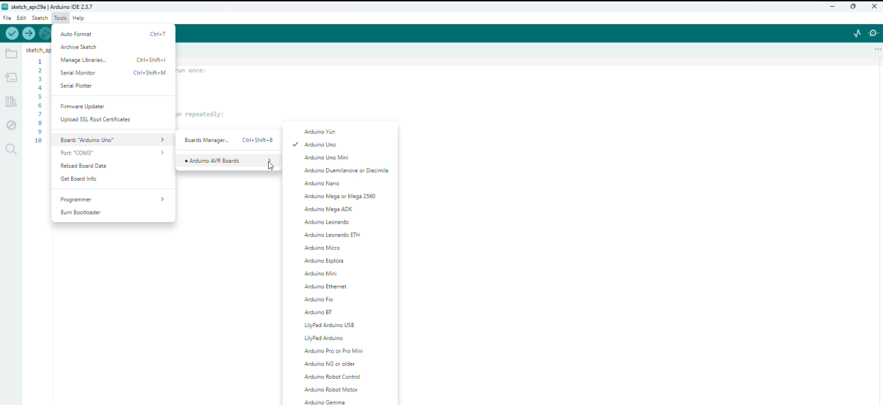
Arduino Setup
To ensure the arduino reed the microcontroller i have as light up doesnot mean its identified , it oly means the electricity pass through it and light it up!
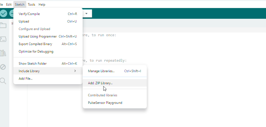
Pulse ZIP library
Before code you need to download the zip file from github for pulse library i attached in the referance section and here is the step to upload the zip file to arduino.
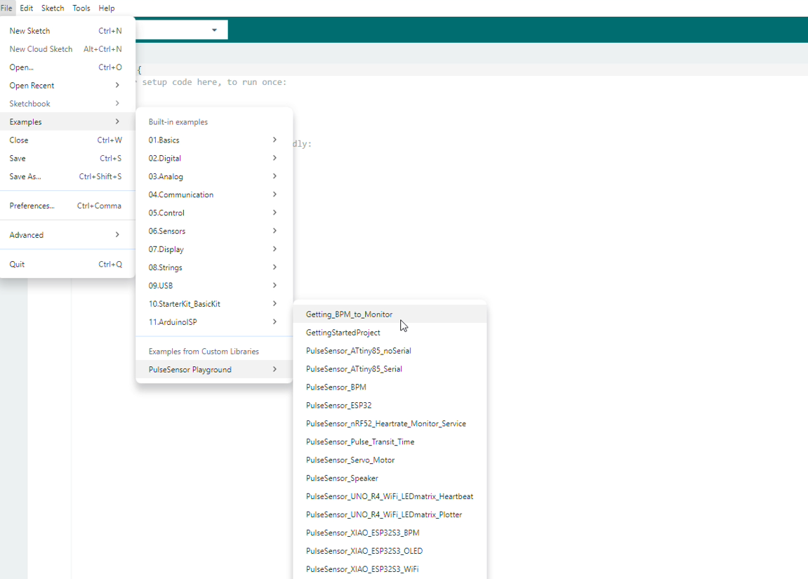
Code Example
Example
From file >> examples>> Pulse>> BPM
After Edit
I changed variables in the code
const int PulseWire = 0;      // PulseSensor PURPLE WIRE connected to ANALOG PIN 0
const int LED = LED_BUILTIN;  // On-board Arduino LED (usually pin 13)
int Threshold = 550;          // Threshold to detect a heartbeat

pulseSensor.blinkOnPulse(LED);  // Automatically blink LED with heartbeat
and added one line for LED to blink with each heeart beat on void setup
#include

// Variables
const int PulseWire = A1;     // PulseSensor PURPLE WIRE connected to ANALOG PIN A1
const int LED = 5;            // LED connected to PIN 5
int Threshold = 550;          // Signal threshold to detect a heartbeat

// Create PulseSensor object
PulseSensorPlayground pulseSensor;

void setup() {

  Serial.begin(115200); // Start Serial Monitor

  // Configure PulseSensor
  pulseSensor.analogInput(PulseWire);
  pulseSensor.blinkOnPulse(LED);
  pulseSensor.setThreshold(Threshold);

  if (pulseSensor.begin()) {
    Serial.println("We created a pulseSensor Object!");
  }
}

void loop() {

  // Print raw signal value
  Serial.println(pulseSensor.getLatestSample());

  // Detect heartbeat
  if (pulseSensor.sawStartOfBeat()) {

    int myBPM = pulseSensor.getBeatsPerMinute();

    Serial.println("♥ A HeartBeat Happened!");
    Serial.print("BPM: ");
    Serial.println(myBPM);
  }

  delay(20);
}
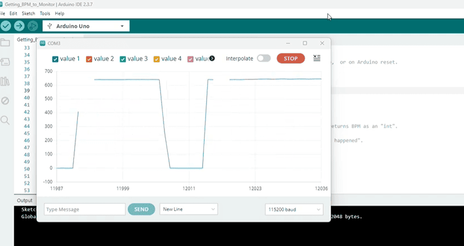
Output
Here is videos showing the output while expirementing the sensor direct with finger interaction and how LED is light up same as seeing the serial visualization to the heart rate and you can see it light up when no touch as emergency and light off when there is heart beat .
From Youtube
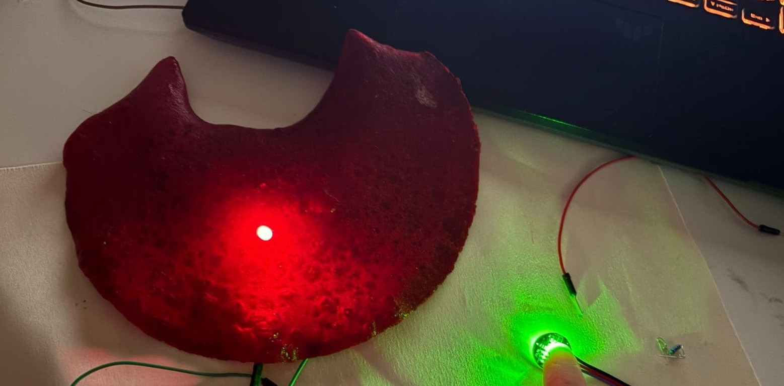
Here i made it with small expirement to pot on and betwen bio material (agar agar) from bio fabricated week, as nit is advised to cover the circit of pulse the back side as a circuit to avoid any harm and same way this is what the week of skin about to use electronic on skin with barrier ,
direct with finger interaction and how LED is light up
Project :Electronic + Bio material
Now after check the electronics and make it it is time to connect togather electronics + bio material agar agar here:
Biomaterial
Using Biomaterial - agar - agar check recipe from bio fabricated weekto be close to skin then attach electronic on it . Here my little cousine was too intrested in the bio material and loved to be the model of this tiny peice !
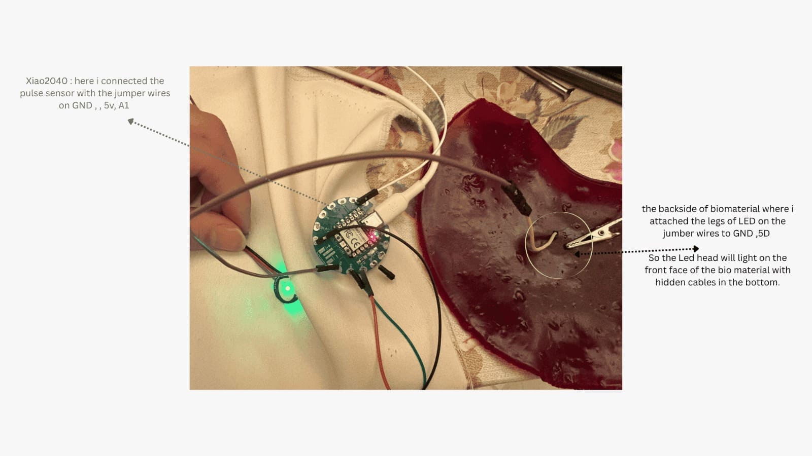
Microcontroller
It could be arduino uno or xiao 2040 which i will be using here as it is hidden and not visible and could give flexibility , check wearable here to know more about it .
LED + Pulse Sensor
 Here you can see LED not interact so here i had two things came to mind that either the LED is burned or the wire is disconnected and after test i decided to try a new LED .
Flora Neopixel + Pulse sensor
with this Pixel i needed to install new library on arduino named "Adafruit NeoPixel" .
The issue here was it need to be solder or stitched so it stay attached as the wires could not stick on it long enough! so that i back to use LED a new one with resistor as you can see in the output.
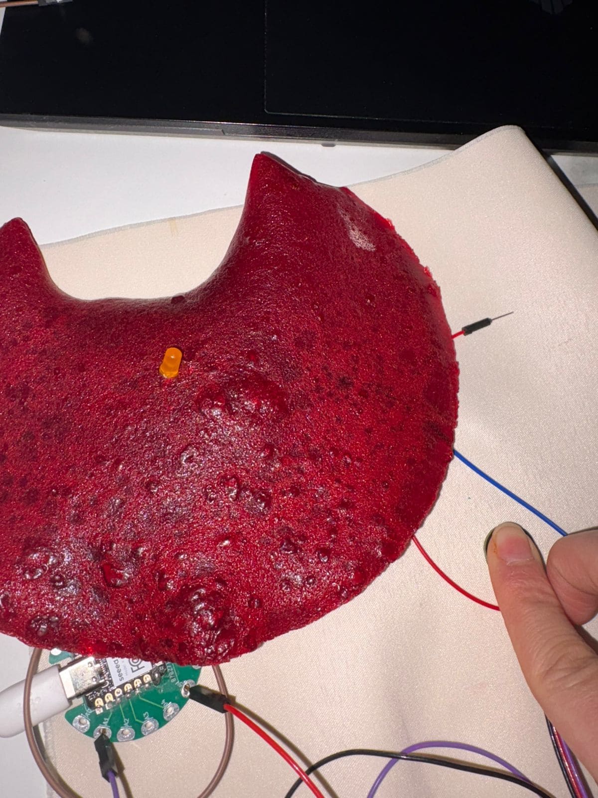
Output
FIxed new LED (add resistor on - but here i have already solder resistance of xiao microcontroller so skip this part) and it worked during the touch if no heart beat the LED automatically turn on and when there is bean >> LED switch off.