5. E-textiles
This week's assignment is on E-textiles and that makes me both excited and nervous. I have never touched electronics before so it will be challenging because there seems to be a lot of foreign concepts, words, tools and components that i need to familiarize myself with and it feels a bit overhwelming.
Lecture
Here's a link to Liza Stark's lecture on E-textiles:
Process and workflow
I started out by making quick and dirty prototypes made of paper and copper foil, in order to understand the basics.
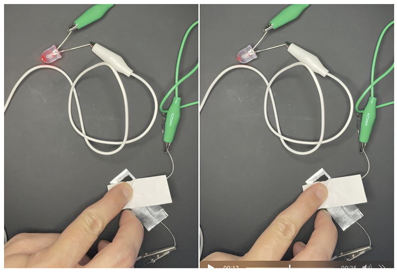
The first thing i tried making is an analog pressure sensor, using conductive foam sandwhiched between 2 layers of foil taped to conductive thread.
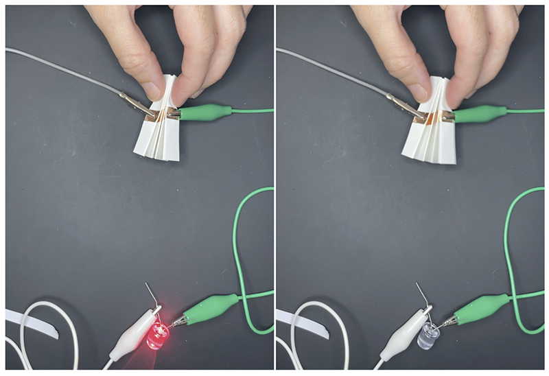
Here i'm testing a digital sensor. I love origami and kirigami, so i was trying to think of ways to incorporate folding into the mix.
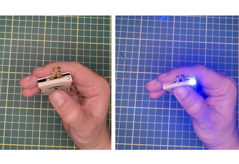
I then looked around my house and asked myself: which objects in my daily life are conductive? I saw my keys on the desk and thought maybe it would be interesting to create a product that interacts with the key. Here's a quick and dirty prototype just to validate my thinking:
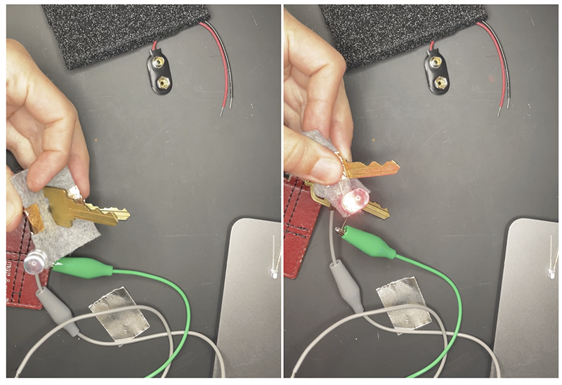
The idea is that by squeezing the key, you complete the circuit and the LED turns on and helps you find your lock in low light conditions.
Digital sensor keyholder
Tools
- Trotec Trotec Speedy 300 Laser cutter
- Soldering station
- Digital Knight 14×16 clamshell heat press
- Adobe Illustrator
Design
First off I gathered materials that were available to me at the lab and that would work for wha i wanted to do:
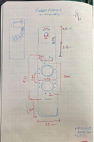
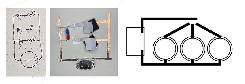
After gathering materials I sketched in my notebook and figured out a schematic with dimensions.
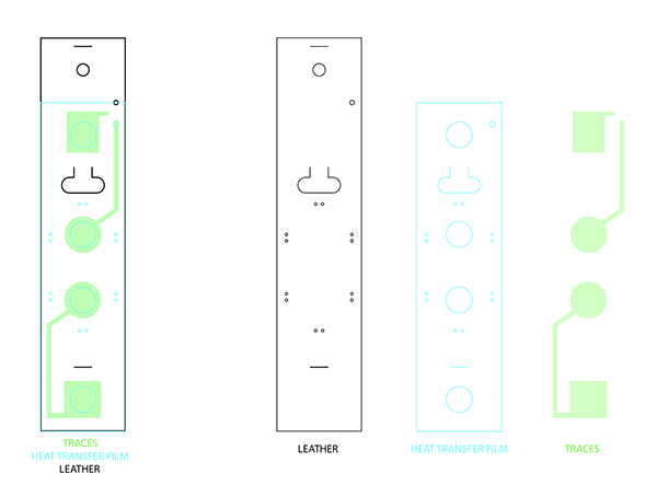
After making a quick paper prototype to validate the dimensions of my keyholder, i started working with illustrator to design each material layer that will make up the cleaner prototype:
- Each layer will be laser cut and assembled in the heat press, into a 3 layer sandwhich construction.
- The rectangular design will fold itself and be secured with a stitch free joint (inspired by modular fashion week). This joint will also serve to secure the key in its place.
- The only area with stitching will be where the tiny holes are: these are for securing the battery in place.
Fabrication
Download the fabrication file here1.
- STEP 1: Laser cutting the parts.
Here are the settings for how i laser cut all of the materials that make up the first prototype.
Trotec Speedy 300
Material: Leather
**Orientation: Back side facing up**

Power: 30
Speed: 60
PPI/HZ: 1000
Passes: 1
Air assist: On
Z-offset: Manual
Trotec Speedy 300
Material: Black heat transfer vynil(laser friendly)
**Orientation: Adhesive facing down (plastic backer facing up).**

Power: 15
Speed: 60
PPI/HZ: 1000
Passes: 1
Air assist: On
Z-offset: Manual
Trotec Speedy 300
Material: Conductive woven
**Orientation: does not matter**

Power: 40
Speed: 60
PPI/HZ: 1000
Passes: 1
Air assist: On
Z-offset: Manual
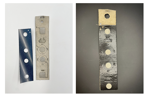
Stack the different layers on top of each other. The bottom layer of the stack is the leather, back side facing up. Second layer of the stack is the conductive woven traces. Third layer is the heat transfer vynil, adhesive side facing down. Place in the Heat press.
14 x 16 Digital Knight Clam shell heat press
Material: Black heat transfer vynil, conductive woven & leather.

Pressure: manual knob
Temperature: 135 celsius
Time: 15 seconds
Challenges
Once the heat pressing is done it's time to insert the LED. I was planning on soldering it but i have never done this before so I started to do tests with scraps of conductive woven and LEDs. At this point i started to realize i should have done this step before desinging because I only designed 2mm of fabric to solder onto. As i do my soldering tests, i realize it's very likely that i will scrap my prototype. But, with limited time, i decided to go for it and hope for the best.
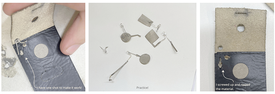
Oops. Well, at least I was mentally prepared for it to fail.
Result
So, in order to validate the design, i patched up the failure points of my prototype with some adhesive copper and assembled it with the key and the battery.
Here i made a document to show how this keyholder is folded and assembled:
Future improvements
I'm happy with the result but there are some things i would improve:
-
I would increase the width of the conductive woven that get welded to the LED, to have a bit more surface to weld to and make sure it doesn't rip like the first time.
-
The keyholder is a bit long and interferes with the key; i would modify the dimensions so that the leather covers only the bow and not the shoulder of the key.
-
The stitching: I didn't think of this but, maybe i should figure out a way to secure the battery that doesn't involve stitching. If the battery dies, the user needs to rip a stitch in order to replace the battery, and stitch it back up. That's not super practical.
Analog sensor
For the analog sensor, I knew i wanted to keep working with LED lights but I wanted to add a level of difficulty and wire multiple LEDs. At the lab, there were red, green and blue LEDs so it made me think of RGB. Maybe i can wire 3 red, green and blue LEDs together and create a RGB mixing keyboard?
Tools
- Trotec Trotec Speedy 300 Laser cutter
- Soldering station
- Digital Knight 14×16 clamshell heat press
Materials
- 3 LEDs: red, green and blue
- Conductive woven
- 2032 3V battery
- Battery holder
- 3M double sided adhesive tape
- Cotton muslin
- Taffeta
- Velostat pressure sensitive sheet
- Conductive thread
Design
I had pretty limited time to do this so I kept the design very basic and went from sketch to design very quickly.
Fabrication
- Once I have my basic design, i can start laser cutting my materials. Download the fabrication file here2.
Here are my laser settings:
Trotec Speedy 300
Material: Conductive woven

Power: 40
Speed: 60
PPI/HZ: 1000
Passes: 1
Air assist: On
Z-offset: Manual
Trotec Speedy 300
Material: Velostat

Power: 20
Speed: 60
PPI/HZ: 1000
Passes: 1
Air assist: On
Z-offset: Manual
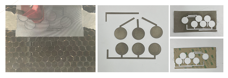
-
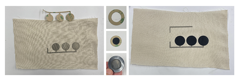
Next I glue my laser cut parts onto my coto muslin. For the velostat circular pads, i cut out a ring of 3M tape so that only the perimeter of the velostat will be glued down, and not the center. I did this because I tried gluing the entire surface but the 3M adhesive is not conductive.
-
After gluing all my parts together i stitched the battery holder to the traces using some conductive thread.
-
Once that is done: the bottom half of the analog sensors are complete. The other half will be glued to a clear taffeta. I didn't take very good pictures so i will try and explain, hopefully it's clear. See notes under the next images.
-
And for the LEDs, i soldered them to the conductive woven. It was a lot easier this time since i planned a wider surface of conductive material to solder to. But, the challenge was in soldering the negative LED leg to the bottom part of the analog sensor, and soldering the positive LED leg to the top part of the analog sensor. It was a bit complicated and i would do it differently next time.
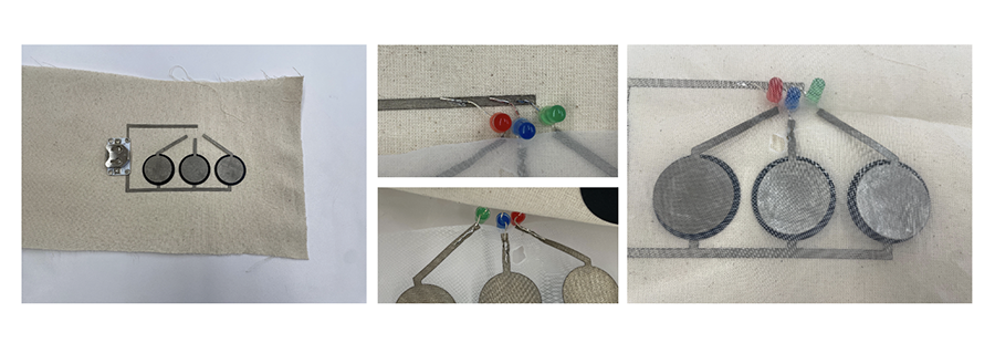
Result
And now the color mixing can begin.
I am happy with the result. I do think i could have put more thought into the design lines, i think they're pretty basic. But the oclor mixing effect is pretty cool! To me, having the 3 LEDs mix this way is a lot more interesting than using one RGB LED. I think there is more dimension.
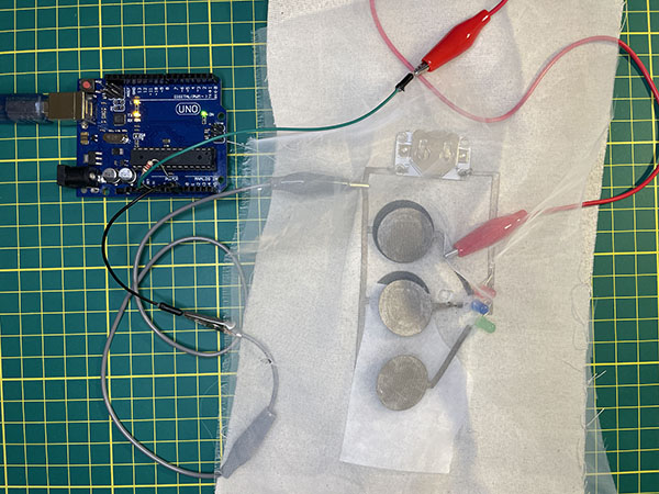
Reading the analog sensor with Arduino
This part was a bit confusing to me, as i have never worked with electronics or arduino before so i asked for help from François, one of the lab instructors who is very good with electronics.
First we wired the sensor to the arduino:
Here's a diagram I made using Tinkercad
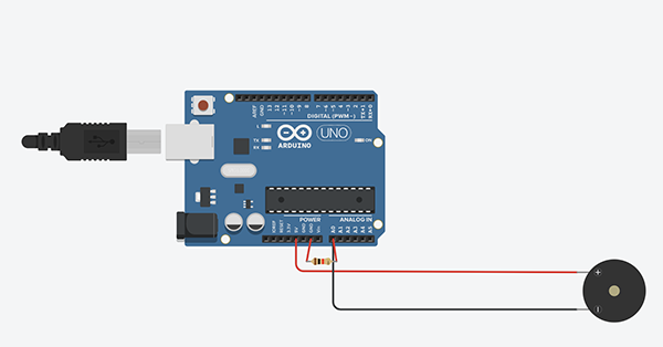
Code Example
For the code, long story short, we have programmed the arduino to read the values coming from the sensor at every second (1000).
Here it is:
const int pin = A0;  // ici on definis une variable qui permettra de definir notre pin analogue
int state = 0; // ici on cree une variable qui nous permettra de ranger l<etat (le comportement) de notre pin (HIGH ou LOW)


void setup() {
  // put your setup code here, to run once:
  pinMode(pin, INPUT);  // ici on identifie ta pin A0 comme etant une entree d<information
  Serial.begin(9600); // ici on apelle une communication entre le arduino et l<ordinateur
}

void loop() {
  // put your main code here, to run repeatedly:
  state = analogRead(pin); // ici on viens chercher l<etat de notre pin A0 (qui sapelle pin) et on la range dans notre variable state
  Serial.println(state); // ici on imprime l<etat de notre pin
  delay(1000);

}