12. Soft robotics
I decided to explore my own ideas for an inflatable soft robot, instead of doing one of the proposed examples (soft gripper, wrist bracelet, etc). My approach was a bit experimental, in the sense that i did not try to design or program a specific outcome. Rather, I let my curiosity lead the way and hoped I would discover something interesting along the way.
In this page, I document 3 different paths of exploration, where I focus on different variables for each exploration.
PATH 1: COMPUTATIONAL PROGRAMMING & SILICONE CASTING
In this exploration path, i focused on 2 things:
-
Exploring computational as a tool for programming inflation behavior: I wanted to look at different patterns generated in grasshopper and see if any of their characteristics would have an impact on the geometry of the inflatable.
-
the silicone fabrication process: I have made many inflatables in the past, but never with silicone, so i was interested in going through the fabrication steps for this material
Tools and materials
- Plexiglass
- Eco-flex 00-50
- Sil-poxy
- Glue paintbrush
- Tube
- Air compressor or Syringe
- rubber gloves
- Stirring stick
- Container for mixing
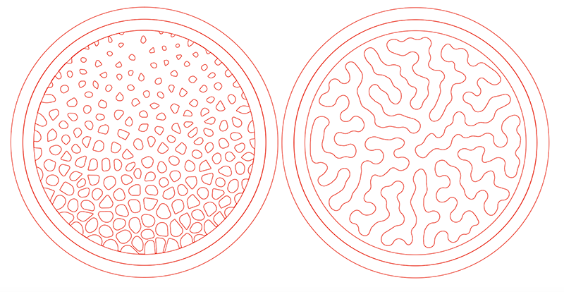
Airflow design: voronoi attractor-point pattern
The first pattern I decided to use is the voronoi pattern, I used this because i had already created it during the computational couture week. Another reason i used this pattern is because I am interested in seeing if the spacing between the voronoi cells has an impact on the geometry of the inflatable. During the computational week, i documented how i created the voronoi pattern, using a point attractor in order to vary the size of the voronoi cells. Varying the cell sizes also ends up creating more space in between the cells, therefore affecting the density of the pattern. In below image on the right, the façade of the building uses this characteristic to create more shade in certain areas, and less shade in other areas.
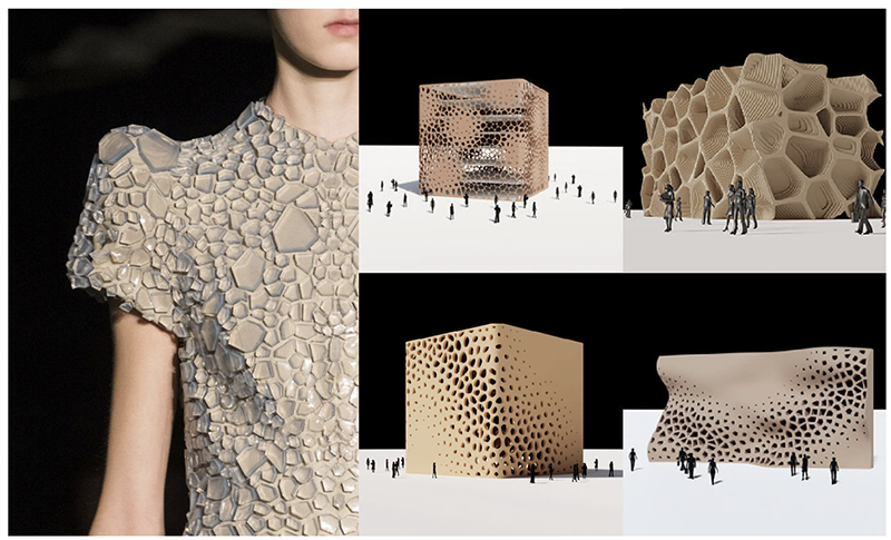
So, how will the spacing between the cells affect the geometry of the airbag? My guess is that the airbag will inflate more in the less dense areas of the pattern, and it will inflate less in the denser areas. Keep reading to find out.
Download the Rhino/gh file here1.
Airflow design: differential growth pattern
The second pattern i decided to explore is a differential growth pattern. The reason i chose it is because i was inspired by a study i found where researchers use computational design to create inflatable deployable structures. Below image is taking from this study.
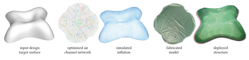
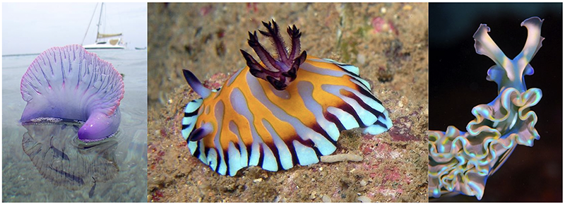
I wasn't able to find the name of this pattern that they are using, among all the information in their research paper. So I tried to find similar patterns by researching grasshopper tutorials and the closest one i found was one on differential growth. I realize the pattern is different, but it has some similarities so I decided to try it out and see what happens. This pattern can be found in so many places in nature, such as in marine creatures, but also in your brain structure🧠.
I have some ideas on how it will turn out, i'm not sure it will inflate and create curvature like the inspiration research, but i am thinking if i vacuum it (instead of inflate it), it might create an interesting wrinkling effect and shrink in size, a little bit like an artificial muscle. A brain ripple shaped artificial muscle?
Download the Rhino/gh file here3.
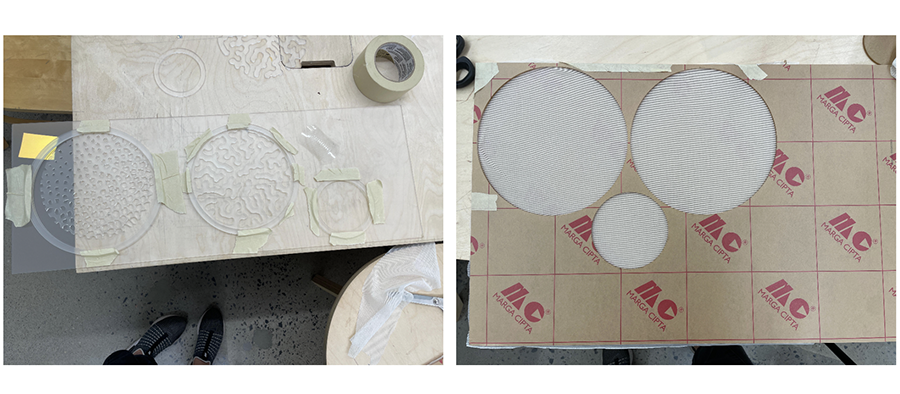
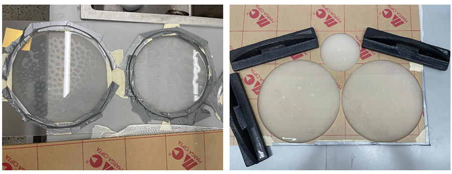
Mold fabrication
The important thing to know about the mold creation is that I fabricated them by stacking layers of plexiglass. I saw this method used by Loes Bogers in the creation of her biosilicone bioplastic and i thought it would be a quick way of trying my ideas out. The mold has 2 parts, 1 part has the air chambers in the designed pattern, and the other part is a full sheet without any designs.
If you want to know more about the creation of the voronoi pattern, I document the creation in the computational couture assignment. You can download the rhino/grasshopper file here1 and you can download the illustrator laser cutting file here2.
For the differential growth simulation pattern, i followed this tutorial.You can download the rhino/grasshopper files here 3 and you can download the illustrator laser cutting file here4.
These are the settings i used for laser cutting the plexiglass:
Trotec Speedy 300
Material: Cast acrylic plexiglass (through-cut)
Material thickness: 3mm

Power: 100
Speed: 0,95
PPI/HZ: 5000
Passes: 1
Air assist: On
Z-offset: Manual
Casting the silicone
Preparing the silicone is a very straight forward process, and i forgot to take photos, but here you can see the specs for the eco-flex 00-50. There is also a video that shows the process of pouring and mixing part A with part B. Also, Eco-flex is expensive so you will want to calculate the amount of silicone you need to use. Here's a link that helps you estimate how much material you will need for your molds.
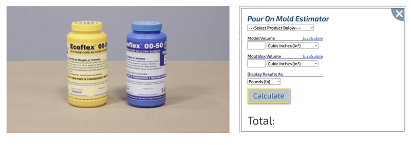
In order to use the tool, you need the volume of your model. I was having trouble with my Rhino document at the time, so I couldn't access the information. Instead I loosely calculated, basing myself on the diameter of my circular pattern and that resulted in me miscalculating. But it was not a big deal because, since i underestimated the amount, all i needed to do was mix a new batch.
Once I had my silicone mixed, I went ahead and poured the silicone into the mold. My mold was very poorly designed, it is just stacked plexiglass and i didn't even use any glue to hold it in place. The only part i secured was the circular frame, which i taped down with duct tape. For the other side of the mold, I used weights to weigh down the plexiglass, and i also taped the edges just in case the silicone were to leak out.
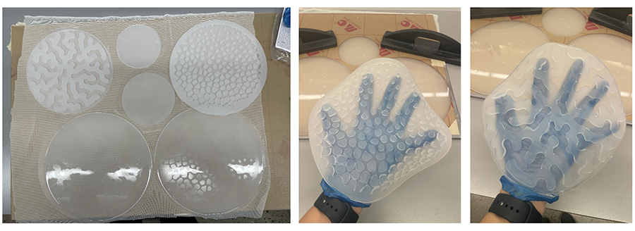
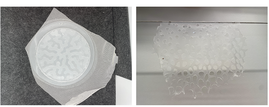
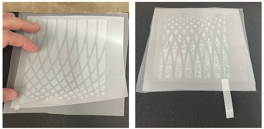
Once you have mixed the silicone, it takes about 45 minutes before it starts to solidify. Then it needs about 4 hours to fully cure. Here are some photos of the molds after 4 hours of curing.
Some observations:
- I like how Part B is nicely embedded into the mesh textile.
- I immediately notice that i messup on the differential growth pattern, i didn't design an edge so I'm not sure how i will close the airbag.
Next step would be to use the sil-poxy in order to close the airbag. To do this i used a painbrush to lay down the sil-poxy on all the areas i wanted to bond. The instructions say it begins to harden after 5 minutes and will take about 1 hour to fully cure. My design had a lot of detail so i needed to hurry up.
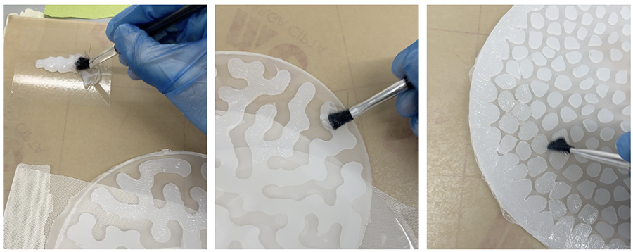
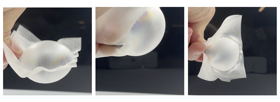
Below is a gif of the voronoi being inflated, here are some thoughts:
- I had a hard time getting the tube connection to be airtight. The only tube i had was super large and the silicone had a hard time wrapping around it. Next time i would design an indentation for to accomodate the volume of the tube.
- It's a bit hard to see in the video, but the side where the voronoi cells are smaller is inflating more.
- That being said, since the cells are so much smaller, the surface area for bonding is also smaller: that resulted in many of the smaller voronoi cells snapping and unbonding. The sil-poxy was not enough too keep the 2 sides of the mold together.
- Overall, I do think the distance between the cells has an impact on the geometry of the airbag. But, it would be more successfull with a pattern that varies the distance between the cells without varying the size of the cells. I'm not sure how i would design that but it would be an interesting challenge.
- I wanted to also try vacuuming it, but i only had a small syringe at the lab, it really wasn't ideal especially since the valve connection was leaky, so I moved on.
- I think this pattern would be more successful with a different method of make. I don't think the silicone is the right making it, i think the results would be more interesting with a flat, 2 layered film construction.
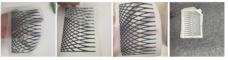
Toughts on the voronoi being injected with fluid:
- The most interesting part about this is that the pattern created by the fluid entering the bladder is almost the same as the differential growth pattern.
PATH 2: COMPUTATIONAL PROGRAMMING & FLAT DOUBLE FILM AIRBAGS
For this exploration path i focused on two things:
- I wanted to test a double film airbag construction.
- I also wanted to try a new computational pattern and understand how it's characteristics affect the behavior of the airbag.
Tools and materials
- 14 x 16 Digital Knight Clam shell heat press
- Trotec speedy laser cutter
- TPU film
- Laser friendly heat transfer vynil
- Double-sided adhesive film
- Baking paper
- self-laminating sheet
Airflow design
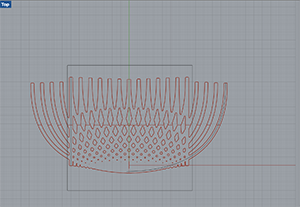
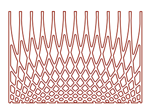
I knew i wanted to explore the Tween curve script I made during the computational couture week, because i have a feeling it will produce interesting movement and i love the design language of this pattern. But, I did need to rework it a bit to fit my new purpose. If you are interested to see the creation of the script, click here.
I don't have great vocabulary to describe these pattenrs but i will try and explain what i was thinking: I created a sort of gradient with the tween curves, so that the diamond shape in between the lines would go from small to bigger. Initially i played around for a long time with the script because i wanted to figure out how to change the thickness of the line in a way where, the line is 2mm thick on one end, and gradually becomes thicker at the other end. But I couldn't figure it out. Being pressed for time, i decided to just go ahead with this and see if it works.
I also wanted to clip the design into a rectangle, but i had trouble finding the right tool to use in grasshopper, so i exported my artwork to illustrator and used the clipping mask function. You can download the Rhino/gh files here5 and the Illustrator file here6.
Fabrication
Before lasercutting my complex shape i decided to test little swatches in order to determine the heat press settings for my materials. I tried a couple of different methods, one with the baking paper as the blocker, and the other using the black vynil as the blocker. I also have a couple of different thicknesses of TPU sheet. I also tried a different swatch, using the double sided adhesive, but i lost the little swatch so I didn't document it.
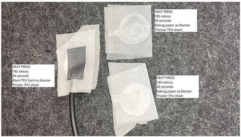
I went through a lot of trial and error and here I document 3 different methods that I tried:
Double-sided adhesive trial
For this trial i am using Double-sided adhesive film and translucent TPU film.
- Step 1: I kiss cut my adhesive film with the laser cutter. A kiss cut is when you have 2 layers of material and you choose your laser settings so that the laser cuts only the top layer and not the second layer. My top layer is the double-sided adhesive and my bottom layer is the carrier paper it comes with. Its a bit hard to tell in the image, but if you look carefully, you can see the laser cut pattern.
Trotec Speedy 300 Material: Double-sided adhesive on carrier paper Type of cut: kiss-cut Power: 5 Speed: 100 PPI/HZ: 1000 Passes: 1 Air assist: On Z-offset: Manual - Step 2: I weed away the parts i don't need.
- Step 3: I am left with the double sided adhesive only where the diamond shapes are. The rest of the artwork has no adhesive, therefore it will not bond.
- Step 4: I heat press the double-sided adhesive onto a TPU sheet. (I am realizing now that my love for translucent materials isn't the best for documenting a process, it's a bit hard to distinguish the layers, i apologize for this)
- Step 5: I heat press a second TPU sheet to create the other side of the airbag.
The heat press settings are important here. The translucent TPU film i am using has a melting temperature of 185 - 220C, and the Double-sided adhesive has a melting temperature of 170 to 190C. So, I set the heat press to 175celsius, since this would be high enough to melt the double-sided adhesive, but low enough to NOT melt the TPU. If the temp is too high, the TPU will bond to itself and my airbag won't inflate.
14 x 16 Digital Knight Clam shell heat press
Material: TPU sheet and Double-sided adhesive

Pressure: manual knob
Temperature: 175 celsius
Time: 30 seconds
I tried to inflate this airbag, and i couldnt get it to open up. It wasn't immediately evident why it was not opening up, so, I decided to move on and try a second way of making the airbag. (I will discover later on why it didn't inflate, stay tuned)
Black vynil as blocker trial
For this trial, i used the black heat transfer vynil and the translucent TPU film. My little round swatch test worked well and it inflated so i figured that this would work.
- Step 1: I laser cut my pattern onto the black vynil.
Trotec Speedy 300 Material: Black heat transfer vynil(laser friendly) Type of cut: Through-cut Power: 15 Speed: 60 PPI/HZ: 1000 Passes: 1 Air assist: On Z-offset: Manual - Step 2: I heat pressed the vynil pattern onto my translucent TPU fabric.
14 x 16 Digital Knight Clam shell heat press Material: Black heat transfer vynil & TPU sheet Pressure: manual knob Temperature: 185 celsius Time: 30 seconds - Step 3: I peeled away the vynil's backer.
- Step 4: I added another layer of TPU sheet and heat pressed it again in order to close the bag. Same settings as the second step.
This airbag ended up not inflating either. 🤔 WHY NOT???
At this point i was a little annoyed but mostly wanted to figure out why it wasn't inflating.
- Did I heat press it too long and the air channels ended up bonding? by inspecting it visually, the channels don't appear to be bonded, so I don't think this is the problem.
- Are the air channels too narrow? This is my suspicion.
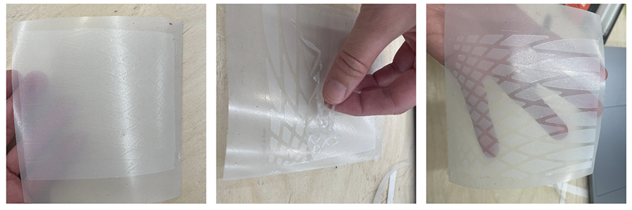
In order to test this, I decided to inject colored liquid inside the bag. I am thinking that if the liquid is capable of going through the paths, than the issue is not the bonding. At first, the liquid didn't go inside the channels, but then, i cut one of the corners off to relieve the pressure inside the bag, and as soon as I did that, the liquid started filling the channels, because it had a path where it could escape. So this validates what i was thinking, bonding is not the issue. The issue is that air compresses, and water doesnt. Water is capable of penetrating those small channels, but air can't because it choses to compress instead.
Larger artwork trial
Informed by my two first failed trials, I enlarged my artwork and tried a third airbag. This time I used self-laminating sheet as the blocker and, I used the translucent TPU film as the airbag material.
Step 1: I laser cut my new enlarged design onto the self-laminating sheet.
Trotec Speedy 300
Material: Self-laminating sheet
Type of cut: Through-cut

Power: 15
Speed: 60
PPI/HZ: 1000
Passes: 1
Air assist: On
Z-offset: Manual
Step 2: I sanwhiched the self-laminating sheet design in between 2 sheets of TPU and heat pressed it together. Note: I place a small removable strip of baking paper where i want my valve to be.
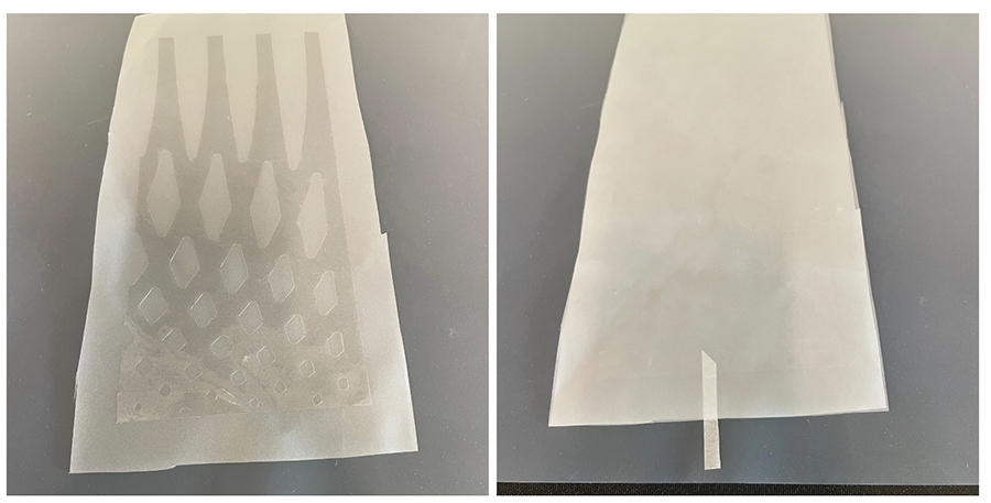
FINALLY!! this one inflated. And there is a bit of movement. It's not dramatic like the silicone grippers, but it's movement. I think that the size of the diamond does have an impact on the movement of the airbag. This is pretty cool because i can imagine this pattern being designed over a larger area. With tweaks to the grasshopper script, you can probably program some interesting shapes into the inflation of the airbag. You can dowload the fabrication file here5.
PATH 3: POLARIZED AIRBAGS
References & Inspiration
In this exploration path, I combine my love for kirigami, computational programming and cross-polarized images, the main focus being on the polarization aspect. It might seem like a very random group of things to put together, but this is something i am thinking of exploring for my final project.
The image on the right is from a study where they investigate how changing the parameters of the kirigami cuts has an impact on the shape of the inflation. The longer the cut, the more it inflates because the material is less restricted. The shorter the cut, the less it inflates because it restricts the material. I would love to go deep into this kind of work, i find it fascinating but i will be focusing mostly on polarization for these experiments.
Tools and materials
- 14 x 16 Digital Knight Clam shell heat press
- Trotec speedy laser cutter
- TPU film
- Baking paper
- self-laminating sheet
Airflow design
I didn't really invest any time into designing the airflow in this, because my main goal was to just test and see what happens when i place airbags in between cross-polarized filters. Instead, i just created quick and dirty prototypes.
Fabrication
I will not go into detail about the fabrication because I already document these fabrication methods in the previous section.
Results
This is a first test that i made very quickly by sandwiching baking paper in between two layers of TPU sheet. I heat pressed it and inflated it. I had to go in with a tweezer to remove the baking paper because i wanted to observe the bag between cross-polarized filters.
So, next I decided to add a layer of material that has more birefringence (If i understand correctly, this is the quality that makes a material change color when viewed between two cross-polarized filter). I decided to use the self-laminating sheet. I would use this material as the blocker in my airbag. Inspired by the kirigami research and some previous trials i have done with kirigami and polarized filters, i decided to quickly laser cut my self-laminating sheet with a kirigami pattern i already had from a previous project. Here is where you can download this pattern6.
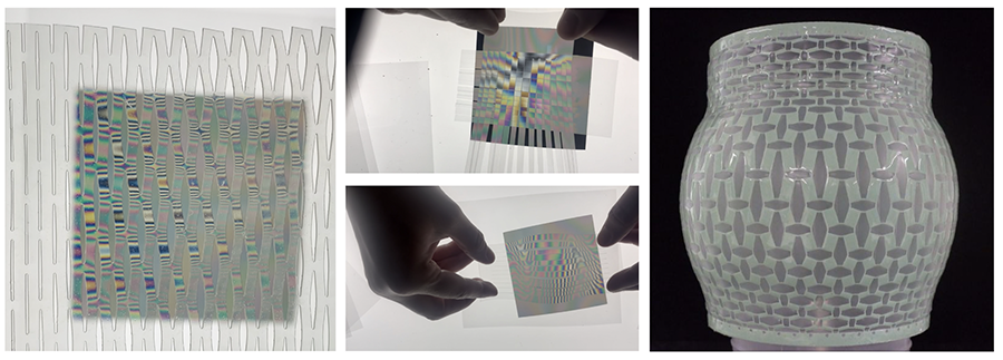
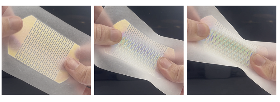
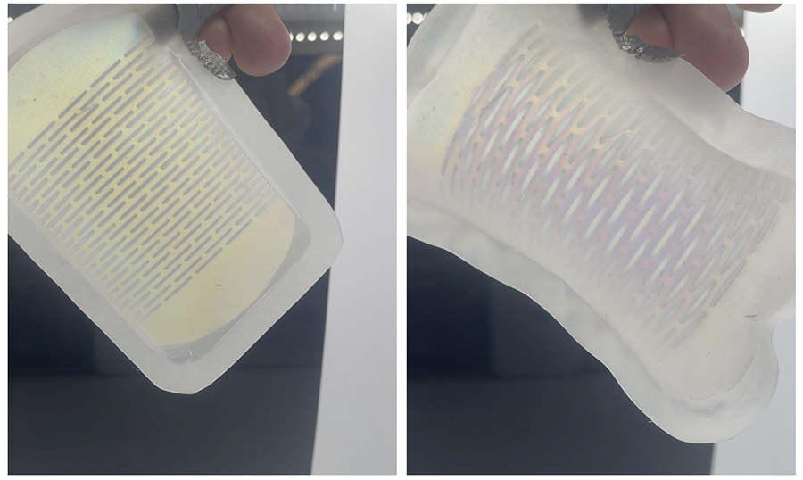
In below photo, i am testing my TPU with the kirigami self-laminating sheet laminated onto it. I stretch it to see if the colors change. They do!
So, I complete the airbag by adding the second layer of TPU and heat pressing it. And I inflate it:
Here's a video:
Next, I tried the tween curve airbag
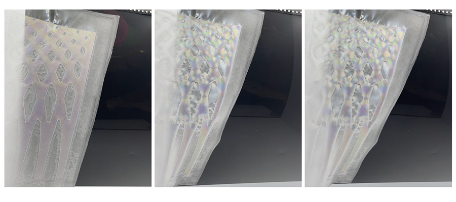
Here's a video:
I love this effect, I think it's so magical to have this color change happening with the inflation. For sure, i think the visual is a little busy, especially in the tween curve airbag. But this is some good experimentation for my final project.