13. Skin Electronics
References & Inspiration
I started out this week's assignment trying to make something with my transit RFID card, but it didn't end up working. You can read section about my RFID failure at the end of this page. But, now that my first idea failed, i started looking for new inspiration and i looked at what some of the other students had already done for this assignment and I was inspired by Mina Mayo-Smith's charlieplexing work.
![]()
Tools
materials
- Arduino Uno
- ATtiny 85 or 45
- SMD LEDs
- Flat back pearl beads
- Thin conductive copper wire (I stripped a cable to get it)
Process and workflow
I found a lot of useful tutorials on charliplexing but they all felt to complicated for my limited understanding of electronics. I found this instructables tutorial showing how to make the simplest charlieplexing layout, with 6 LEDs. This is perfect for me, as I easily get overwhelmed by new information, I need to start simple.
Here are also some other tutorials i looked at:
- Tutorial charlieplexing LEDs on Attiny
- Charlieplexing smd leds
- Diagonal grid layout
- how to replace led (if i need to salvage LEDs from old lamp)
- attiny arduino charlieplexing
- tinkercad charlieplexing
Step 1: test the LED integration
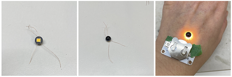
I had an aesthetic in mind for the integration of the LED and this aesthetic is based on the fact that i find the LED light harsh and not enjoyable to look at. I wanted to try something that makes it more tolerable to look at and i thought of backlighting.
I found these interesting beads from a store in Montreal while i was out fabric shopping and i thought they might work for covering the LED and creating a backlighting effect.
Initially i wanted to use conductive thread, but after a few tests, i couldn't get it to solder. Instead i stripped an electrical wire and extracted some very thin copper wire and my soldering tests worked great. Once i tested my LED, I hot glued a pearl onto it to validate the aesthetic i am going for, and I love it, it's clean and minimal and has an astral quality, it reminds me of an eclipse.
Step 2: Testing the simplest charlieplexing layout
Here's a diagram showing the simplest possible charlieplexing layout using 3 pins on the arduino.
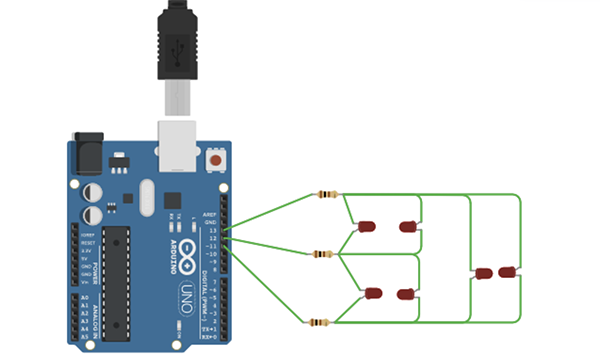
I found some TINY spare LEDs from the lab (2mm x 1.6mm). I was curious to see how difficult it is to create something with such small LEDs. The important thing is too figure out a setup to hold the LEDs in place: some simple double sided tape worked well. Note: pay attention to the polarity of the LEDs in the diagram.
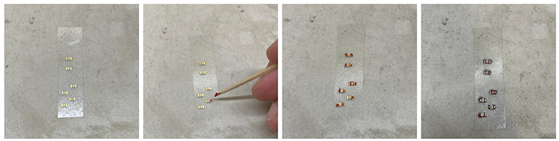
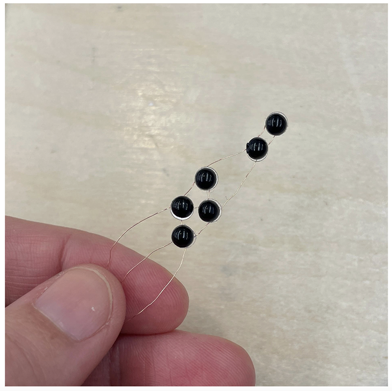
Once the doldering done, I added some smaller beads with some double sided sticky tape. This is probably not a viable long term solution, it's just to prototype.
Step 3: Testing the code
I downloaded the code from the instructables tutorial, there's a link at the bottom of the page that sends you to a github page, and you can download the arduino sketch from there.
And also, here it is:
/* Charliplexing 6 LEDs
--------------------------------------------------------------------------------
Row 1 (R1): Arduino Pin 13
Row 2 (R2): Arduino Pin 12
Row 3 (R3): Arduino Pin 11
--------------------------------------------------------------------------------
variable    pinMode      state
 L           OUTPUT       LOW
 H           OUTPUT       HIGH
 Z           INPUT        LOW
---------------------------------------------------------------------------------
     R1 (Pin 13)      R2 (Pin 12)     R3 (Pin 11)
L1    L                 H                Z
L2    H                 L                Z
L3    Z                 L                H
L4    Z                 H                L
L5    L                 Z                H
L6    H                 Z                L
-----------------------------------------------------------------------------------
LED    Cathode      Anode
1         R2          R1
2         R1          R2
3         R3          R2
4         R2          R3
5         R3          R1
6         R1          R3
---------------------------------------------------------------------------------
*/

const int LED_1 = 13;     //LED row 1
const int LED_2 = 12;     //LED row 2
const int LED_3 = 11;     //LED row 3

void setup()
{
}

void loop()
{
  //turn on LED L1
  pinMode(LED_1, OUTPUT);     //row 1
  digitalWrite(LED_1, LOW);
  pinMode(LED_2, OUTPUT);     //row 2
  digitalWrite(LED_2, HIGH);
  pinMode(LED_3, INPUT);      //row 3
  digitalWrite(LED_3, LOW);

  delay(100);

  //turn on LED L2
  pinMode(LED_1, OUTPUT);     //row 1
  digitalWrite(LED_1, HIGH);
  pinMode(LED_2, OUTPUT);     //row 2
  digitalWrite(LED_2, LOW);
  pinMode(LED_3, INPUT);      //row 3
  digitalWrite(LED_3, LOW);

  delay(100);

  //turn on LED L3
  pinMode(LED_1, INPUT);      //row 1
  digitalWrite(LED_1, LOW);
  pinMode(LED_2, OUTPUT);     //row 2
  digitalWrite(LED_2, LOW);
  pinMode(LED_3, OUTPUT);     //row 3
  digitalWrite(LED_3, HIGH);

  delay(100);

  //turn on LED L4
  pinMode(LED_1, INPUT);     //row 1
  digitalWrite(LED_1, LOW);
  pinMode(LED_2, OUTPUT);    //row 2
  digitalWrite(LED_2, HIGH);
  pinMode(LED_3, OUTPUT);    //row 3
  digitalWrite(LED_3, LOW);

  delay(100);

  //turn on LED L5
  pinMode(LED_1, OUTPUT);    //row 1
  digitalWrite(LED_1, LOW);
  pinMode(LED_2, INPUT);     //row 2
  digitalWrite(LED_2, LOW);
  pinMode(LED_3, OUTPUT);    //row3
  digitalWrite(LED_3, HIGH);

  delay(100);

  //turn on LED L6
  pinMode(LED_1, OUTPUT);
  digitalWrite(LED_1, HIGH);
  pinMode(LED_2, INPUT);
  digitalWrite(LED_2, LOW);
  pinMode(LED_3, OUTPUT);
  digitalWrite(LED_3, LOW);

  delay(100);
}
Results
It worked instantly! I didn't really run in to any issues, which feels like a miracle. And the code is simple enough that i was able to understand it, and play around with it a little bit. This was a small win that i needed!
Note: I don't like the blue light aesthetic, I didn't notice that i picked a blue LED. It's okay for this prototype, but next round, i want to make it with the warm LED's i ordered from digikey.
Tinkercad
Ok, so now that i understand the simplest charlieplexing code and wiring, i feel confident to try a more complex layout. I think i will try it out in Tinkercad, just like Mina Mayo-Smith did. I am not making it as complex as Mina, because i don't feel confident yet, just a little bit more complex than the first one. I'm pretty proud of myself, i wrote the code myself, adapting the instructables code I downloaded from the instructables tutorial for 6 LEDs.
Here's the code:
/* Charliplexing 14 LEDs
--------------------------------------------------------------------------------
Row 1 (R1): Arduino Pin 13
Row 2 (R2): Arduino Pin 12
Row 3 (R3): Arduino Pin 11
Row 4 (R4): Arduino Pin 10
Row 5 (R5): Arduino Pin 9
--------------------------------------------------------------------------------
variable    pinMode      state
 L           OUTPUT       LOW
 H           OUTPUT       HIGH
 Z           INPUT        LOW
---------------------------------------------------------------------------------
     R1 (Pin 13)      R2 (Pin 12)     R3 (Pin 11)
L1    L                 H                Z
L2    H                 L                Z
L3    Z                 L                H
L4    Z                 H                L
L5    L                 Z                H
L6    H                 Z                L
-----------------------------------------------------------------------------------
LED    Cathode      Anode`
1         R2          R1
2         R1          R2
3         R3          R2
4         R2          R3
5         R3          R1
6         R1          R3
---------------------------------------------------------------------------------
*/

const int LED_1 = 13;     //LED row 1
const int LED_2 = 12;     //LED row 2
const int LED_3 = 11;     //LED row 3
const int LED_4 = 10;     //LED row 4
const int LED_5 = 9;      //LED row 5

void setup()
{
}

void loop()
{
    //turn on LED L1
  pinMode(LED_1, OUTPUT);     //row 1
  digitalWrite(LED_1, LOW);
  pinMode(LED_2, OUTPUT);     //row 2
  digitalWrite(LED_2, HIGH);
  pinMode(LED_3, INPUT);      //row 3
  digitalWrite(LED_3, LOW);
  pinMode(LED_4, INPUT);      //row 4
  digitalWrite(LED_4, LOW);
  pinMode(LED_5, INPUT);      //row 5
  digitalWrite(LED_5, LOW);

  delay(50);

  //turn on LED L2
  pinMode(LED_1, INPUT);     //row 1
  digitalWrite(LED_1, LOW);
  pinMode(LED_2, OUTPUT);     //row 2
  digitalWrite(LED_2, LOW);
  pinMode(LED_3, OUTPUT);      //row 3
  digitalWrite(LED_3, HIGH);
  pinMode(LED_4, INPUT);      //row 4
  digitalWrite(LED_4, LOW);
  pinMode(LED_5, INPUT);      //row 5
  digitalWrite(LED_5, LOW);

  delay(50);

  //turn on LED L3
  pinMode(LED_1, INPUT);     //row 1
  digitalWrite(LED_1, LOW);
  pinMode(LED_2, INPUT);     //row 2
  digitalWrite(LED_2, LOW);
  pinMode(LED_3, OUTPUT);      //row 3
  digitalWrite(LED_3, LOW);
  pinMode(LED_4, OUTPUT);      //row 4
  digitalWrite(LED_4, HIGH);
  pinMode(LED_5, INPUT);      //row 5
  digitalWrite(LED_5, LOW);

  delay(50);

  //turn on LED L4
    pinMode(LED_1, INPUT);     //row 1
  digitalWrite(LED_1, LOW);
  pinMode(LED_2, INPUT);     //row 2
  digitalWrite(LED_2, LOW);
  pinMode(LED_3, INPUT);      //row 3
  digitalWrite(LED_3, LOW);
  pinMode(LED_4, OUTPUT);      //row 4
  digitalWrite(LED_4, LOW);
  pinMode(LED_5, OUTPUT);      //row 5
  digitalWrite(LED_5, HIGH);

  delay(50);
  //turn on LED L5
  pinMode(LED_1, OUTPUT);     //row 1
  digitalWrite(LED_1, HIGH);
  pinMode(LED_2, OUTPUT);     //row 2
  digitalWrite(LED_2, LOW);
  pinMode(LED_3, INPUT);      //row 3
  digitalWrite(LED_3, LOW);
  pinMode(LED_4, INPUT);      //row 4
  digitalWrite(LED_4, LOW);
  pinMode(LED_5, INPUT);      //row 5
  digitalWrite(LED_5, LOW);

  delay(50);

  //turn on LED L6
  pinMode(LED_1, INPUT);     //row 1
  digitalWrite(LED_1, LOW);
  pinMode(LED_2, OUTPUT);     //row 2
  digitalWrite(LED_2, HIGH);
  pinMode(LED_3, OUTPUT);      //row 3
  digitalWrite(LED_3, LOW);
  pinMode(LED_4, INPUT);      //row 4
  digitalWrite(LED_4, LOW);
  pinMode(LED_5, INPUT);      //row 5
  digitalWrite(LED_5, LOW);

  delay(50);

  //turn on LED L7
  pinMode(LED_1, INPUT);     //row 1
  digitalWrite(LED_1, LOW);
  pinMode(LED_2, INPUT);     //row 2
  digitalWrite(LED_2, LOW);
  pinMode(LED_3, OUTPUT);      //row 3
  digitalWrite(LED_3, HIGH);
  pinMode(LED_4, OUTPUT);      //row 4
  digitalWrite(LED_4, LOW);
  pinMode(LED_5, INPUT);      //row 5
  digitalWrite(LED_5, LOW);

  delay(50);

  //turn on LED L8
    pinMode(LED_1, INPUT);     //row 1
  digitalWrite(LED_1, LOW);
  pinMode(LED_2, INPUT);     //row 2
  digitalWrite(LED_2, LOW);
  pinMode(LED_3, INPUT);      //row 3
  digitalWrite(LED_3, LOW);
  pinMode(LED_4, OUTPUT);      //row 4
  digitalWrite(LED_4, HIGH);
  pinMode(LED_5, OUTPUT);      //row 5
  digitalWrite(LED_5, LOW);

  delay(50);

  //turn on LED L9
    pinMode(LED_1, OUTPUT);     //row 1
  digitalWrite(LED_1, LOW);
  pinMode(LED_2, INPUT);     //row 2
  digitalWrite(LED_2, LOW);
  pinMode(LED_3, OUTPUT);      //row 3
  digitalWrite(LED_3, HIGH);
  pinMode(LED_4, INPUT);      //row 4
  digitalWrite(LED_4, LOW);
  pinMode(LED_5, INPUT);      //row 5
  digitalWrite(LED_5, LOW);

  delay(50);

  //turn on LED L10
    pinMode(LED_1, INPUT);     //row 1
  digitalWrite(LED_1, LOW);
  pinMode(LED_2, INPUT);     //row 2
  digitalWrite(LED_2, LOW);
  pinMode(LED_3, OUTPUT);      //row 3
  digitalWrite(LED_3, LOW);
  pinMode(LED_4, INPUT);      //row 4
  digitalWrite(LED_4, LOW);
  pinMode(LED_5, OUTPUT);      //row 5
  digitalWrite(LED_5, HIGH);

  delay(50);

  //turn on LED L11
    pinMode(LED_1, OUTPUT);     //row 1
  digitalWrite(LED_1, HIGH);
  pinMode(LED_2, INPUT);     //row 2
  digitalWrite(LED_2, LOW);
  pinMode(LED_3, OUTPUT);      //row 3
  digitalWrite(LED_3, LOW);
  pinMode(LED_4, INPUT);      //row 4
  digitalWrite(LED_4, LOW);
  pinMode(LED_5, INPUT);      //row 5
  digitalWrite(LED_5, LOW);

  delay(50);

  //turn on LED L12
    pinMode(LED_1, INPUT);     //row 1
  digitalWrite(LED_1, LOW);
  pinMode(LED_2, INPUT);     //row 2
  digitalWrite(LED_2, LOW);
  pinMode(LED_3, OUTPUT);      //row 3
  digitalWrite(LED_3, HIGH);
  pinMode(LED_4, INPUT);      //row 4
  digitalWrite(LED_4, LOW);
  pinMode(LED_5, OUTPUT);      //row 5
  digitalWrite(LED_5, LOW);

  delay(50);

  //turn on LED L13
    pinMode(LED_1, OUTPUT);     //row 1
  digitalWrite(LED_1, LOW);
  pinMode(LED_2, INPUT);     //row 2
  digitalWrite(LED_2, LOW);
  pinMode(LED_3, INPUT);      //row 3
  digitalWrite(LED_3, LOW);
  pinMode(LED_4, INPUT);      //row 4
  digitalWrite(LED_4, LOW);
  pinMode(LED_5, OUTPUT);      //row 5
  digitalWrite(LED_5, HIGH);

  delay(50);

  //turn on LED L14
    pinMode(LED_1, OUTPUT);     //row 1
  digitalWrite(LED_1, HIGH);
  pinMode(LED_2, INPUT);     //row 2
  digitalWrite(LED_2, LOW);
  pinMode(LED_3, INPUT);      //row 3
  digitalWrite(LED_3, LOW);
  pinMode(LED_4, INPUT);      //row 4
  digitalWrite(LED_4, LOW);
  pinMode(LED_5, OUTPUT);      //row 5
  digitalWrite(LED_5, LOW);

  delay(50);


}
Next steps
Next I would like to successfully program this into the Attiny so that i can be untethered from the Arduino. I'm not sure yet if I will build the more complex circuit.
Toughts on applications
I decided to have the LEDs facing the skin for aesthetic reasons, but it made me wonder if there are any benefits or drawbacks to doing this, health wise. Is it okay to have LEDs right up against your skin? So I looked into it and found this monstrosity, which is great if you don't mind looking like Jason from Friday the 13th:

One of the early thoughts i had was to create a veil-like circuit that covers part of the face. I was thinking of it just as an aesthetic piece but I'm realising there could actually be some therapeutic benefits. And it wouldn't it be amazing if this red light therapy mask didn't make you look like someone who's coming to kill you in your sleep?
I found this article about the use of LEDs for therapeutic purposes. I don't know how reputable clevelandclinic is for this type of information, but they are claiming all sorts of skin care benefits, such as benefits for acne, psoriasis, hair loss, ecszema, wrinkles, rosacea, etc. I also found this article by harvard health (probably a more reputable source) saying that scientists say LED skin treatments are safe but there is little evidence they actually work, because there aren't enough large studies.
One use of light therapy which is accepted by scientists and proven to work is light therapy for SAD (seasonal affective disorder). I myself suffer from this and can't live a functional life without my lightbox. Here's an article by mayoclinic about the benefits of light therapy for SAD and here's an interesting article on choosing a light box. This last article is espcially interesting because it gives clues as to what the design considerations are for a light therapy device. I've seen light therapy glasses so I think it's possible to design something that is less bulky and a bit more stylish...
RFID failure
Before looking into LEDs, I wanted to create a useful accessory i could use for transit. I was inspired by Loes Boger's amazing RFID skin tattoo that makes her bow down to the london transit system. Pretty funny.
I did some reasearch to understand how RFIDs work and to find inspiration on what to do with an RFID. Here's some of this research:
- How RFIDs work
- You can unlock doors with RFID
- Tesla's use RFID to unlock the door
- How to program an RFID sensor with Arduino
- RFIDs enable digital business cards
- Tutorial on how to make an RFID bracelet
Following the info in some of these tutorials, I bought some acetone and submerged my opus card in it. I left it on the window ledge in my airbnb's vestibule because it smelled bad. Looking back, I probably should have just covered it. I don't know if the temperature has an impact on if this works or not? But, it did not work. some of the plastic just didn't want to dissolve and the chip ended up falling apart before the plastic.
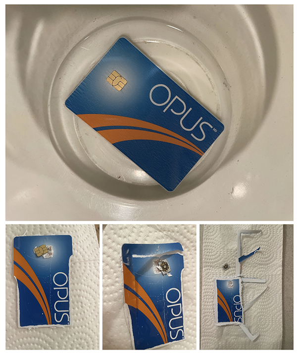
My theories on why it didn't work: - Temperature? - Not covering the container? - The pastic used in this Opus card is just not disolvable by acetone?
I didn't find any troubleshooting info on the web, no one has gone through this so I'm not really sure what to do from here.
Maybe i won't figure out the Opus card for now...But i would like to do something with RFID's in the future, when i have the time. I like the idea of having a silicone bracelet or a ring for my house key, for example.