8. Wearables
Lecture notes
Programming an ATtiny
I looked at this tutorial to help me program the ATtiny with my Arduino Uno. These are the tools required to follow the tutorial:
Wiring an ATtiny on the breadboard
The tutorial was relatively easy to follow. The first step is to wire the ATtiny on the breadboard. The annoying part here was to figure out which pins are which.
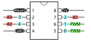 This diagram shows the order of the pins, but my ATtiny didn't have a half circle on it, instead it had a full circle. So I assumed it was the same thing as the half circle on the diagram.}{ width=150
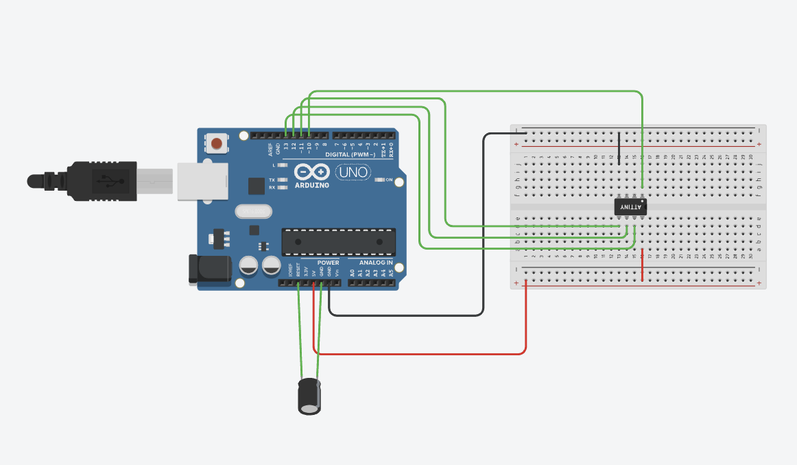
Here I made a clear wiring diagram with Tinkercad.
Program the Arduino
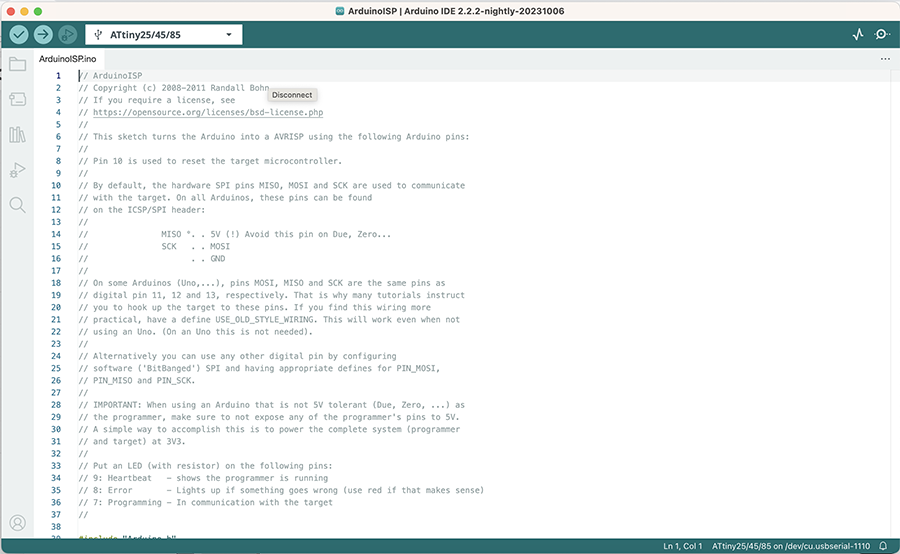
Next, you have to configure the arduino as a serial programmer that can program other chips. This is pretty simple too, it only requires ou to select the "ArduinoISP" sketch from the "Examples" menu and to upload it.
Add the capacitor
This step requires you to add the 10uF Capacitor and connect it between the ground and reset pin on the arduino. Nothing worth mentioning here other than paying attention to the polarity of the capacitor.
ATtiny core files
I struggled a bit with this step because the file they are having you download is not there. I wasn't sure what to do if the file wasn't there because I didn't really have a good understanding of what that file was, so i got a bit stuck and frustrated at this step. Annie, my instructor helped me out and forwarded me another tutorial to follow, see step 3.
Program the ATtiny
Once I finished following that other tutorial, I came back to original instructables tutorial to complete the steps.
Tools menu / Board / ATtiny85 (W/ Arduino as ISP)
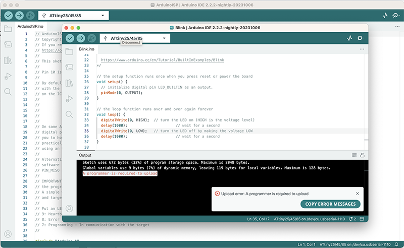
Then open a basic blink example and change the 13 pin to 0, and program a blink behavior. Here you can program a behavior from the LED if you want but I just kept the uploaded the blink example as is.
Test the circuit
 To test the circuit, I added the 220 ohm resistor to the 5th pin. Then, I connected a LED between the resistor and the 5V. If the blink example uploaded properly, the light should be blinking. To make sure the Attiny is programmed, I removed all the wires except for the ones connected to ground and 5V. }{width=150
Driver Circuit
Tools & materials
- Alligator clips
- Paper
- Copper adhesive tape
- Adjustable output power supply
- N-channel MOSFET
- 1N4001 diode
- 10k ohm resistor
- Kapton tape
Making the circuit
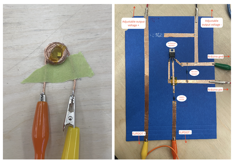
So, what i have understood (not sure if I am using all the right vocabulary) is that the flipdot actuator requires a higher voltage than the Arduino is capable of supplying. This means we will need to supplement with an external power source if we want to program and test the flipdot actuator. In order to do this, we need to create a driver circuit.
A driver circuit is a circuit that allows you to control a power load with low voltage (Arduino) but the current for the load is sinked with a different source (external power source).
In order to understand all this, I create really rough prototypes of the driver circuit and the flipdot actuator.
Code
This is the code I used to program the flip dot. I kept it very simple, asking it to go on HIGH for 1000 and on LOW for 500.
const int led = 9;


void setup() {
  //put your setup code here, to run once:
  pinMode(led,OUTPUT);
}

void loop() {
  // put your main code here, to run repeatedly:
  digitalWrite(led,HIGH);
  delay(1000);
  digitalWrite(led,LOW);
  delay(500);
}
Testing the rough flipdot actuator
And here is the result, a video showing what happens to the magnet. It doesn't flip like the cleaner flipdot actuators because i am using a single coil and a cube shaped magnet. This is just to test the process and I will make a cleaner actuator after.
Flipdot Actuator
Now that I understood how to program an actuator using Arduino, a driver circuit and an external power source, I wanted to make a cleaner flipdot actuator.
Tools & materials
These are the tools & materials I used to create the cleaner actuator:
- Soldering station
- Digital Knight 14×16 clamshell heat press
- Magnetic hematite beads
- Conductive wire
- Leather
- Double-sided adhesive film
- Conductive woven
Making a cleaner flipdot actuator
I tried to find a clean way to embed the coil into a textile. I first tried soldering the wire to conductive woven. I wanted to use just the conductive oven because I like the aesthetic, but it doesn't have enough body to support the coil, it's too thin. However it does weld nicely to it. So then i thought maybe i can laminate the conductive fabric to something else that has a bit more body.
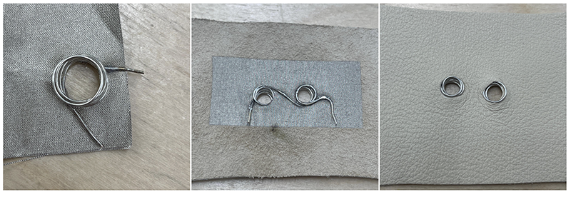
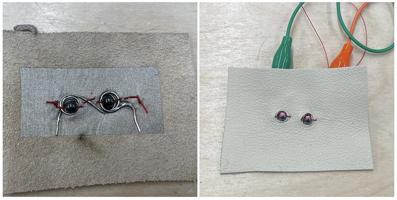
Then I found some magnetic hematite beads, stitched them to my coils using a regular thread and i drew a little pink dot onto one side of the bead.
Result
I didn't completely like the way it looked, i mainly don't like that we see the read thread. So I covered it with a felt that matches the color of the hematite bead. In the video, you can see me switching the polarity manually by changing the alligator clips (I apologize for the unstable camera)
Fabric Speaker
Tools and materials
- Digital Knight 14×16 clamshell heat press
- Double-sided adhesive film
- Conductive woven
- Textile, I used a powermesh
Making the fabric speaker
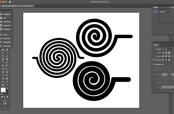
I created coil artwork using illustrator. I am testing 3 different variations, i am curious to see how the thickness of the trace affects the speaker. I also designed one where the coil doesn't end in the middle, because i noticed the coils in all examples I've see end at the center and I'm curious to know if that is necessary. Here are the files1
First step of the fabrication: I laminated the Conductive woven to some Double-sided adhesive film using the heat press.
Here are the settings I used on the heat press:
14 x 16 Digital Knight Clam shell heat press
Material: Conductive woven & Double-sided adhesive film

Pressure: manual knob
Temperature: 135 celsius/ 275 farenheit
Time: 15 seconds
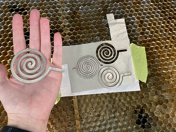
Next step, I laser cut my coils into my conductive/adhesive composite.
Trotec Speedy 300
Material: Conductive woven with double-sided adhesive

Power: 50
Speed: 60
PPI/HZ: 1000
Passes: 1
Air assist: On
Z-offset: Manual
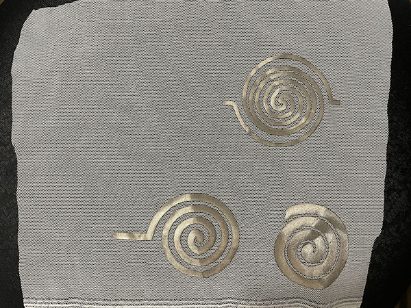
Next step, I laminated the coils onto my power mesh, using the heat press. Some of the parts moved in the heat press, and as a result, one of the coils is messed up and the traces are overlapping. Next time I'll use thermal tape to keep the pieces in place.
14 x 16 Digital Knight Clam shell heat press
Material: Conductive, double-sided adhesive & power mesh.

Pressure: manual knob
Temperature: 135 celsius/ 275 farenheit
Time: 15 seconds
Mono amp
To test the speakers, I decided to follow Liza Stark's tutorial to make amp, but sadly i haven't been able to get it to work.
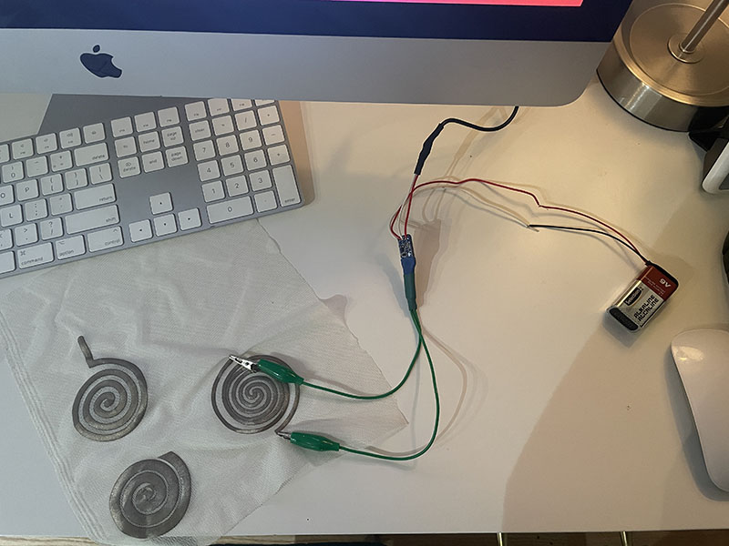
I am not sure why it isn't working, my guess would be that i wired something wrong, and I have a feeling it's because of the audio jack. The audio jack had different wiring from the one in Liza Stark's tutorial, so maybe I didn't do it right.