9. Textile Scaffold
STRING ART RESEARCH
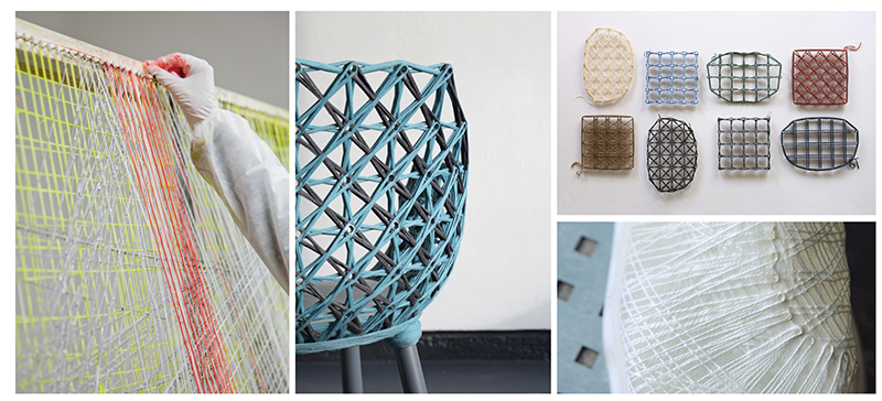
Last week I created a pegboard that allows me to wrap string around pegs in order to create textiles. I was busy figuring out how to automate the string art concept so i didn't get the chance to explore different textile swatches. So, for this week I would like to try some different string patterns along with bioplastic recipes.
Tools
- Laser cut pegboard
- Mechanical pen for stringing
- Pot, cooker, spoon, scale
- Baking paper
PROCESS
Pegboard
During the Open source hardware assignment I documented how to create a pegboard for textile experimentation, using plexiglass and a laser cutter. I will be using this pegboard to create my swatches. My intention is also to create bioplastic recipes that i will pour onto the textile swatches. In the video below, I've placed a baking paper on my pegboard and i am pinning down pegs in different pegboard holes.
Note that the pegs will leave a hole in the material, as the bioplastic will not be able to fill that space. I personnaly don't mind this, i think that the holes can have a purpose (adding breathability, drainage, etc) If you don't want holes all over your swatch, you will need to place the pegs in the periphery. You will see examples of this in swatches 1 and 2.
Stringing
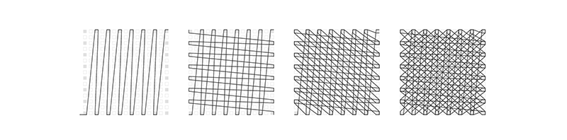
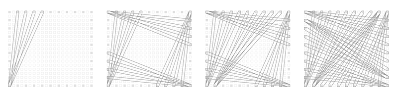
Here I am stringing yarn around the pegs in a pattern I've come up with on the spot. I want to try different color yarns but also different patterns and their impact on the textile.
Here's a different point of view showing how I maneuver around the pegs with the pen as a tool.
I created 7 variations that you will see later on in this documentation.
Bioplastic recipes
After strining my various swatches, I started to prepare a recipe i wanted to try. I based myself on Loes Bogers biofoil recipe and made 2 variations. All i did was to change the amount of glycerin because i wanted to understand the impact of glycerin on bioplatics.
Prepare the recipe for biofoil 1(flexible) by collecting the ingredients necessary, to be found in the list below:
=== **ingredients for biofoil 1(flexible)**

    * Gelatin powder 24gr
    * Glycerine 18gr
    * Water 200gr

=== **ingredients for biofoil 2**

    * Gelatin powder 25gr
    * Glycerine 11gr
    * Water 200gr

=== **tools**

    * Pot
    * Spoon
    * Cooker
    * Scale
    * Mold

=== **recipe instructions**

    * Weigh your ingredients
    * Bring the water to the boil
    * Add the glycerine
    * Add the gelatine
    * Keep the cooker on low while stirring gently to avoid making bubbles
    * Simmer and slowly stir the mixture for 20 minutes on low heat.
    * Let the liquid cool down for a few minutes, until the consistency becomes like syrup.
Pouring Bioplastic
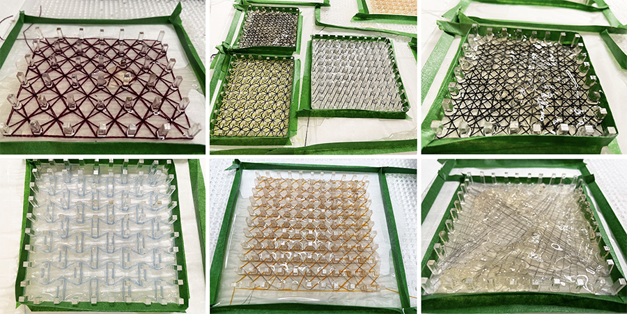
Once my recipe was ready to pour (syrup like consistency), I poured the mixture onto the various string swatches. There are a couple of swatched where i waited a little too long before pouring, and the recipe had started to solidify and it was a little bit lumpy.
Drying Bioplastic
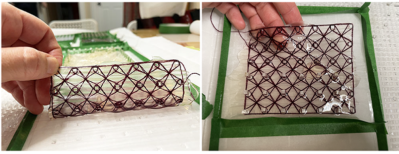
The solidifying happens quite quickly. I was able to remove some pegs after only 1 hour. I was too curious and wanted to see how it was drying. One thing i noticed is that the baking paper starts to create waves or ripples as the mixture solidifies and this ripple is transferred to the material. I don't really mind, I find it kind of interesting but if you don't want this to happen, you might want to look into a paper that holds its shape a little more and won't ripple.
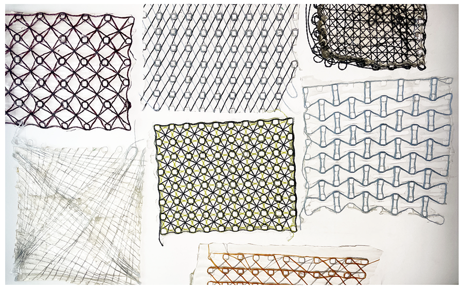
Results Overview
After letting the plastics dry for 24 hours i removed all the pegs and here is an overview of the results
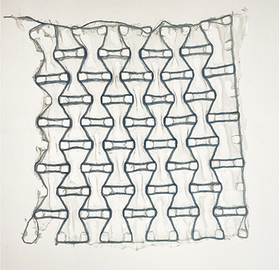
Swatch 1
Some notes:
- This swatch uses the biofoil 1(flexible) recipe.
- I waited too long before pouring the bioplastic mixture and as a result the texture and thickness are very uneven and lumpy.
- This swatch only has pegs on the edge of the swatch (not on the inside), therfore there are not internal holes.
In the following sections i document each swatch individually along with diagrams of the patterns I created.
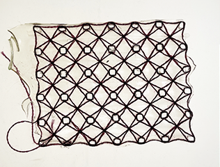
Swatch 2
Some notes:
- This swatch uses the biofoil 1(flexible) recipe.
- I waited too long before pouring the bioplastic mixture and as a result the texture and thickness are very uneven and lumpy.
- This swatch only has pegs on the edge of the swatch (not on the inside), therfore there are not internal holes.
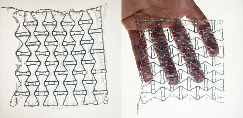
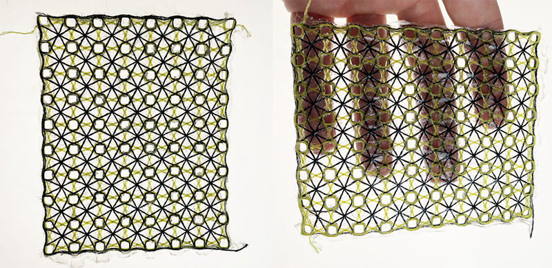
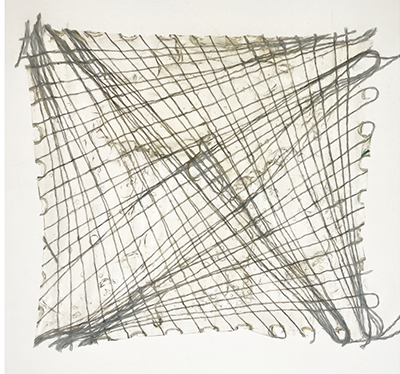
Swatch 3

Some notes:
- This swatch uses the biofoil 1(flexible) recipe.
- I like the visual appeal of this pattern the most.
- This is the first swatch i poured from this mixture and the result is really even. There are noticeable ripples that formed because of the baking paper deforming.
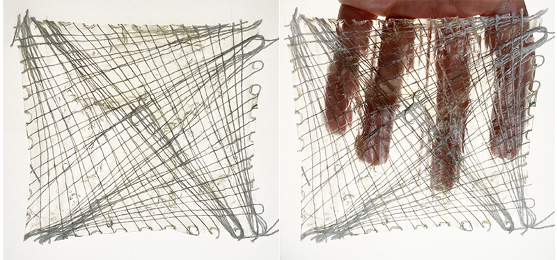
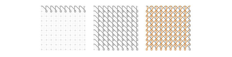
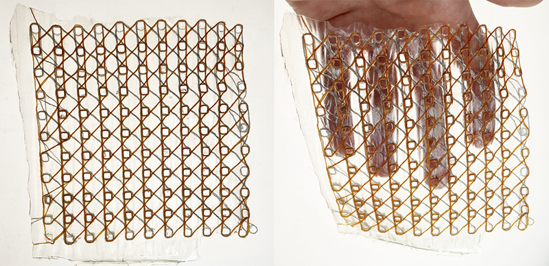
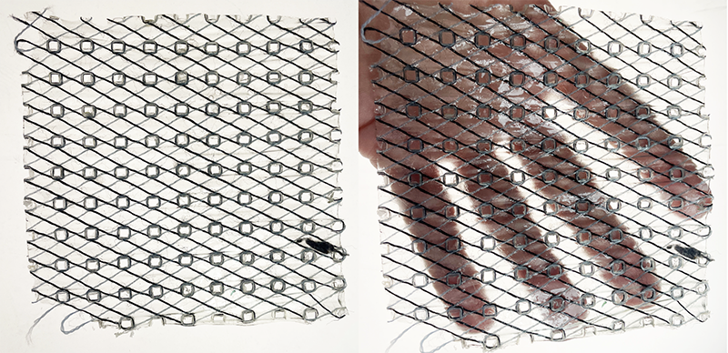
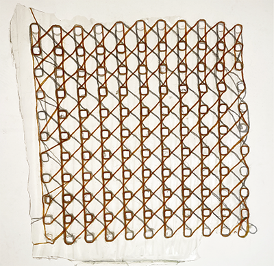
Swatch 4

Some notes:
- This swatch uses the biofoil 2 recipe.
- The bioplastic recipe was still a bit runny when i poured it into this swatch. The mixture ended up leaking in the crevices so the result is very thin and inconsistent coverage.
- The mixture also ended up pooling around the yarns so there is a lot of space in between the yarn that doesn't have any material, it creates perforations.
- I think this pattern could work as an auxetic if the biofoil recipe allowed for some stretch.
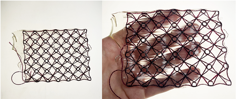
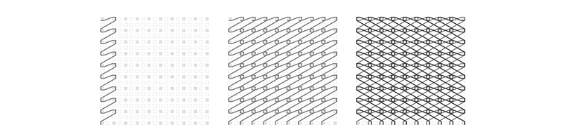
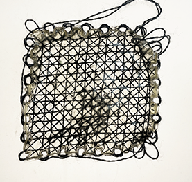
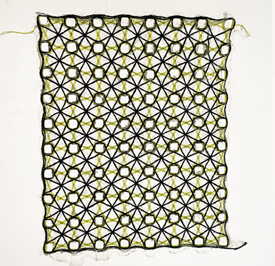
Swatch 5
Some notes:
- This swatch uses the biofoil 2 recipe.
- The bioplastic was at the right consistency when i poured this one, the coverage is pretty uniform but it is very thin.
- I like the visual appeal of this pattern.
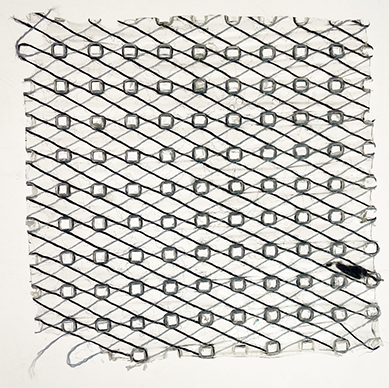
Swatch 6
Some notes:
- This swatch uses the biofoil 2 recipe.
Swatch 7
Some notes:
- This swatch uses the biofoil 2 recipe.
Recipe results
| Material pic | Material name | polymer | plastifier | solvent |
|---|---|---|---|---|
 |
biofoil 1(flexible) | Gelatin powder 24gr | Glycerine 18gr | Water 200gr |
 |
biofoil 1(flexible) | Gelatin powder 24gr | Glycerine 18gr | Water 200gr |
 |
biofoil 1(flexible) | Gelatin powder 24gr | Glycerine 18gr | Water 200gr |
 |
biofoil 2 | Gelatin powder 25gr | Glycerine 11gr | Water 200gr |
 |
biofoil 2 | Gelatin powder 25gr | Glycerine 11gr | Water 200gr |
 |
biofoil 2 | Gelatin powder 25gr | Glycerine 11gr | Water 200gr |
 |
biofoil 2 | Gelatin powder 25gr | Glycerine 11gr | Water 200gr |
Next
I was hoping the different pattern geometries would have a functional impact on the swatches. But, as far as i can tell, they don't, other than visual interest. Perhaps i would need to do strength testing to find out if the different geometries offer more/less strength. I can thoerize that the swatches with denser patterns would be stronger, and the less dense patterns would be less strong. This can be interesting if you want to program the amount of strength needed out of the material, depending on what you are designing.
I also think it would be more interesting to try this with a bioplastic recipe that has some stretch. I can imagine the strings being programmed in a way where they impact the stretch of the material. Imagine incorporating multiple patterns into one swatch/product and being able to zonally program the ammount of stretch you want as well as the direction of the stretch.
Also, aesthetically speaking, i like cloudy, semi-transparent aesthetic more than the clear glossy. If i were to pursue more of this work i would look for some bioplastics with different visual properties.
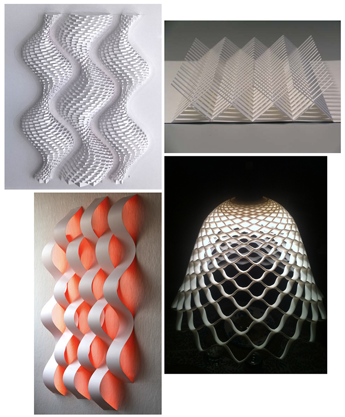
LEATHER MOLDING INSPIRATION
For the second part of the assignment, I really wanted to try leather molding and of course, i was guided by my love for kirigami and complex geometric patterns. I was also inspired by a slide in Anastasia's presentation that showed a combination of laser cutting and molding. This made me think of the japanese are of Ullagami, which is a combination of kirigami(cutting) and origami(folding). This, i think, would be an interesting route to explore.
LEATHER MOLDING RESEARCH
I tried to find an existing grasshopper script that could create something like the top left image from Ullagami. I found an interesting script here and I played around with it for while but i had a hard time getting it to do what i want.
Since I had to arrange time with the lab to use the CNC, I had to figure out a design really quickly and I didn't have enough time to figure out how to make my mold with this script. I am linking it here, because I want to try it again when i have more time, but for now i need to move on.
TOOLS & MATERIALS
- High density polyethylene board
- Veg-Tan leather
- CNC SignMax SMX4896
- Grasshopper
- Rhino 3D
- Fusion 360
- Trotec Speedy 300 Laser cutter
PROCESS
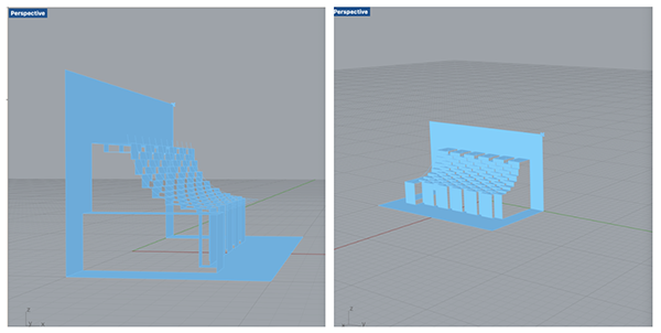
I didn't figure out how to use the grasshopper script to make a mold and a cutting pattern, but playing around with it allowed me to observe the Ullagami geometry from all angles and how it works. I figured i could create a mold myself in rhino. I've done some hands-on explorations in the past with paper (I had a big origami phase) so I already understood it on a visual and kinesthetic level. But, doing this on the computer is different and more difficult in my opinion.
But, the Ullagami design can be broken down into 2 parts:
- Origami: I will design a mold in order to create folds in the material.
- Kirigami: I will design a pattern which will be laser cut into the material.
Design
Origami
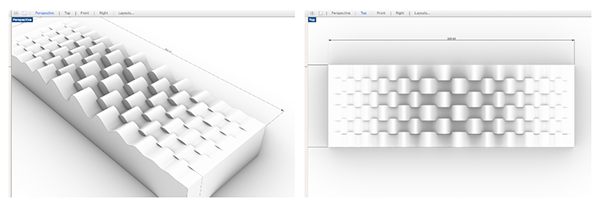
- I started by drawing a sine wave on my x axis. This would be my folding element.I thought it would be interesting to make it smooth and curved instead of a 90 degree angle.
- Next I mirrored the sine wave along the x axis.
- Next I extruded both sine waves along the y axis and alternated them, keeping them overlapped with each other by 5mm.
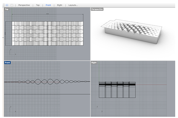
Here's a rendered view of my mold. This is only the bottom part of the mold. I had to then do a boolean difference to create the top part of the mold.
Download the STP model file here 1.
Kirigami
This part consists of projecting the fold measurements onto a flat 2D surface to create the laser cutting design. I transferred to illustrator because i was running out of time and have issues with Rhino.
- I imported the profile of my sine waves into illustrator.
- Using the Document info window (needs to be set to OBJECT in the top right drop-down menu) I was able to extract the dimensions of my sine waves. These need to be measured between the point where the mirrored sine waves intersect.
- Next, I copied those dimensions into a flat pattern of straight lines.
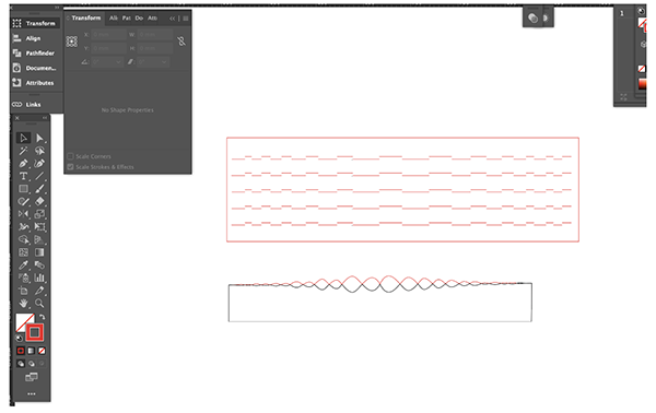
I'm sure there is a better way to do this in rhino but it takes me way longer to figure out. It's not always possible when there is an approaching deadline.
Download the kirigami file here 2.
CAD TO CAM
Once i was done making my mold in rhino, i had to export it as an .stp file and open it using the Fusion360.
Here are the important steps:
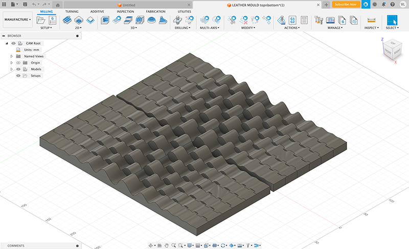
Load model in Fusion 360
Load your model and make sure you select the MANUFACTURE space and not the design space. The model should appear in the workspace as such.
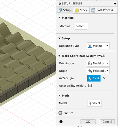
Create new setup
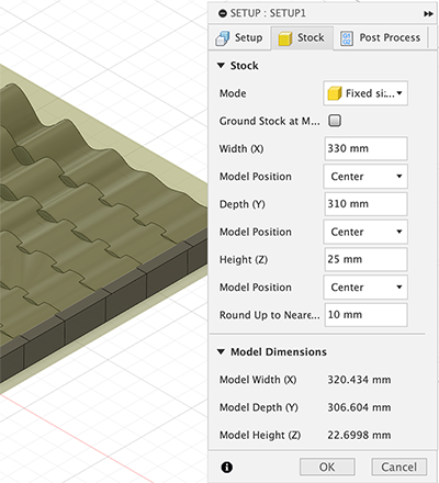
In the left menus, select setup and create a new setup. Here I set the following infos: - Select the machine - Set the origin: select the point on the model which will be the origin. - Select operation type: milling - Select model: click on the 3d model - Select Fixed stock and enter the material dimensions: width, length and height.
3D parallel operation
We are going to be doing a 3D parallel operation, which means we will be generating a parallel toolpath for the cnc to follow.
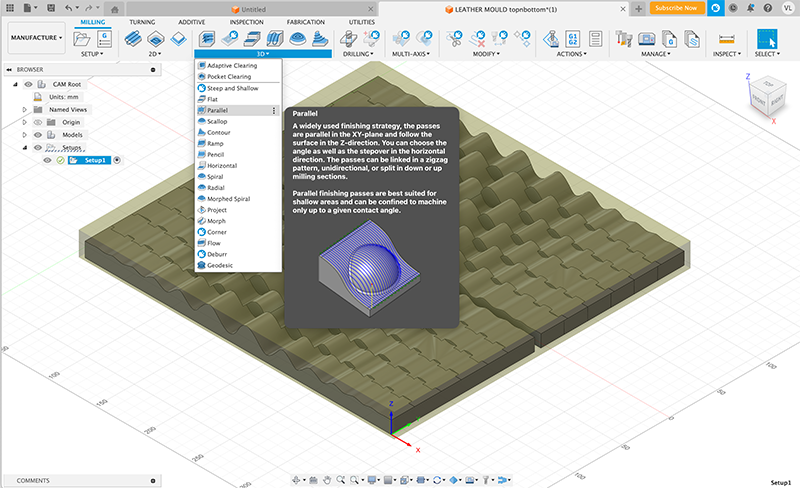
There will be a pop-up menu where the following info needs to be specified:
- Tool tab: Select the tool (I used a 6mm ball end mill) & specify the speed settings. I used this website to help decide the settings. They have proposed settings for different materials and also have tools to calculate your own settings.
- Geometry tab: Select the surfaces on the model which will be milled with a 3D parellel path.
- Passes tab: specify tolerance. The default was 0.01mm but this generated a 8hour long milling time so I reduced it to 0.5mm and the time estimate becomes way shorter.
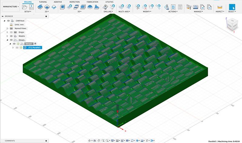
Click OK and it generates a preview with time estimate.
2D contour cut
I then added a second step to cut the perimeter of the model, this is a simple 2D contour cut.
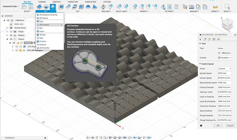
Again, this leads to a pop-up menu where certain information needs to be specified:
- Tool tab: select tool and speeds settings. I used the same as the 3D parallel operation.
- Geometry tab: select the contour of the model, the perimeter. And I added tabs manually by selecting 1 tab per side on the model.
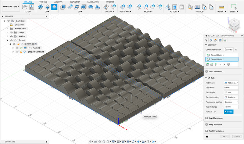
Click ok and it will generate a new preview and time estimate for this operation.
Generate .nc file
Finally, in order to create a file that the CNC can read, go to the Actions drop down menu and select Post Process and this will generate a .nc file that can be loaded onto the CNC with a usb stick.
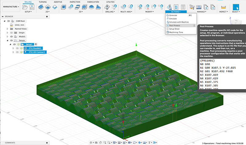
Download the .NC file here 3.
CNC milling
Once the .nc file is generated, we were ready to use the CNC. I didn't take many photos of the process because i was focused on listening to François instructions.
The main steps and things to remember when getting ready to use the CNC:
- Be cautious and wear protective equipment: hearing protection and safety goggles.
- Upload .nc file from USB stick onto the CNC interface.
- Bolt down the material onto the sacrificial wood bed. Make sure the bolts are all evenly secured so the material is leveled. Check with a level.
- Drive the CNC head to the bottom left corner of your material and set the origin.
- Set the Z axis by lowering the tool to the surface of the HDPE material.
- Before beginning, make sure nothing is in the way of the gantry, clean anything that might interfere with the process.
- Start the vaccuum
- Step back and start the machining.
It didn't work on the first try, the CNC was not even touching the surface of the material even though we set the z axis right. So i went back to my FUSION360 file and realised i had set the origin in the wrong corner. Once i fixed this, we were ready to go.
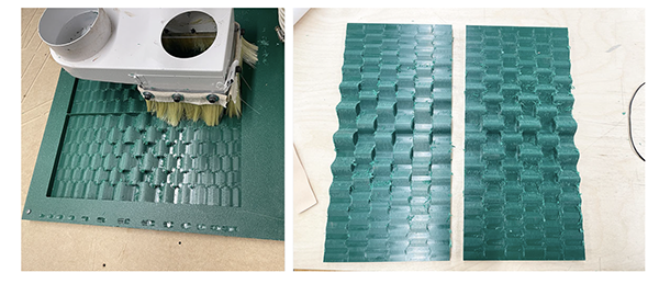
It looks great, but sadly, i forgot to create an offset between the two parts of the mold, so when i put them together, they don't fit. This is something that can be done either in Rhino or in the CAM step in Fusion360. I will know for next time.
This is not a huge deal and since i still had a lot of things to get done, I decided to keep moving forward without the use of the second mold.
Testing
Now I am moving forward and need to test my kirigami pattern. I start off by using a cotton muslin to test my pattern. I am glad i did this test step because my pattern ended up not being right the first time. The positions of the kirigami cuts didn't exactly reflect the positions on the mold, i forgot to mirror the cuts.
Wet moulding
Once i had tested my kirigami pattern, i laser cut it into my veg leather. Here is the fabrication file.
Trotec Speedy 300
Material: Veg leather
Material thickness: 0.75mm

Power: 25
Speed: 0,60
PPI/HZ: 1000
Passes: 1
Air assist: On
Z-offset: Manual
For the molding part, it kept it very simple:
- All i did was lay the leather onto the mold and press the material down into the valleys. This worked well for the middle areas of the design, where the valleys are more pronounced. But along the edges, where the valleys are more subtle, the material has nothing to hold onto, so it didn't work as well.
- I filled a spray bottle with water and misted the leather.
- I let it dry overnight.
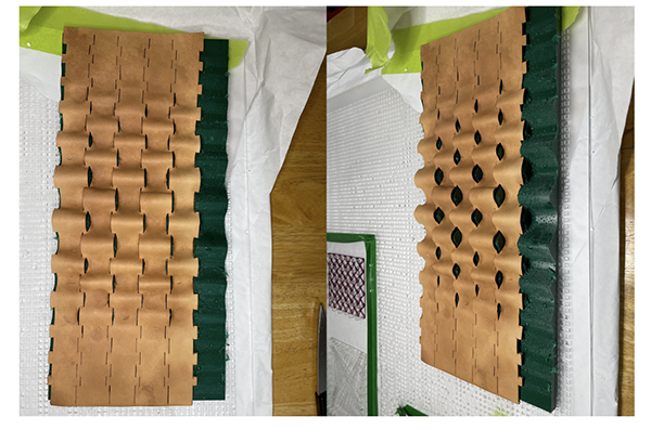
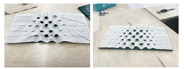
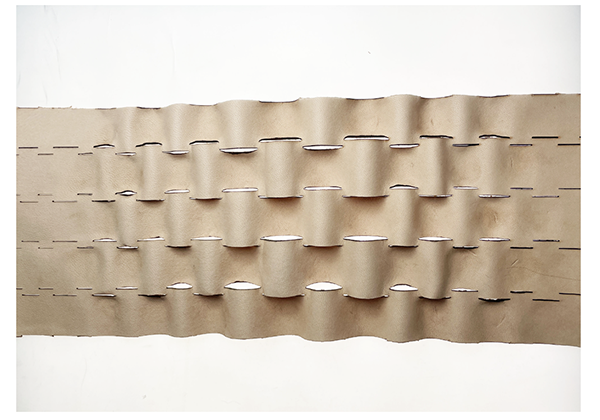
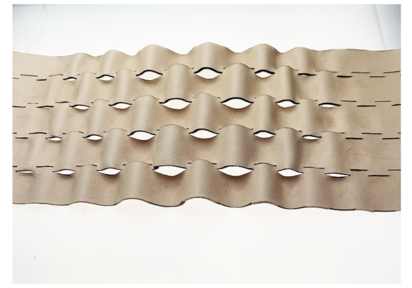
Results
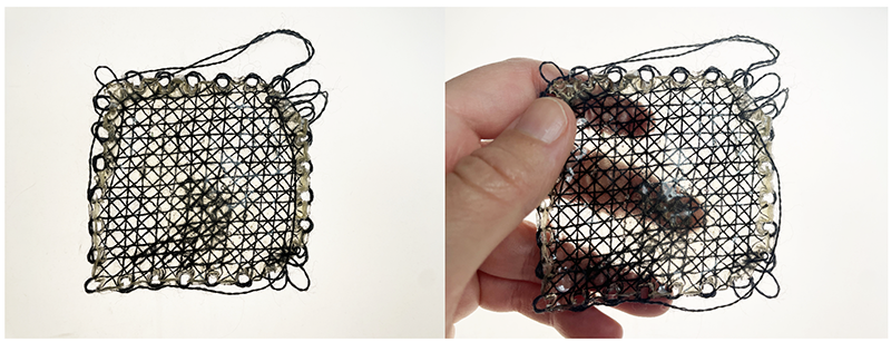
The result is interesting. I would like to try this again but with more complexity, a denser pattern (less space between the kirigami cuts). I think it would be more impactful.
The folding is interesting also because it adds stretch to the material.
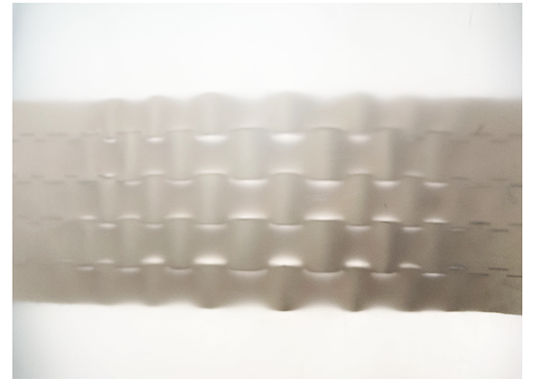
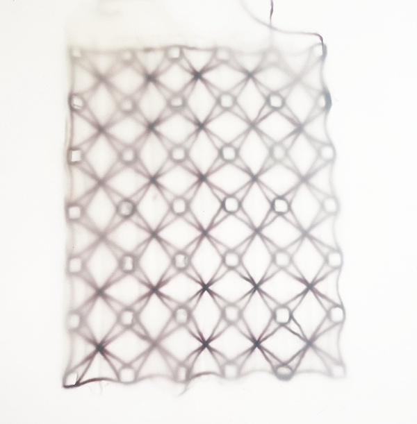
 And here is it photographed behind a diffusion filter. I find this particularly interesting for the way it interacts with the light. You can really see better how the kirigami cuts are orienting or directing the light. I can imagine creating an architectural light with this technique.